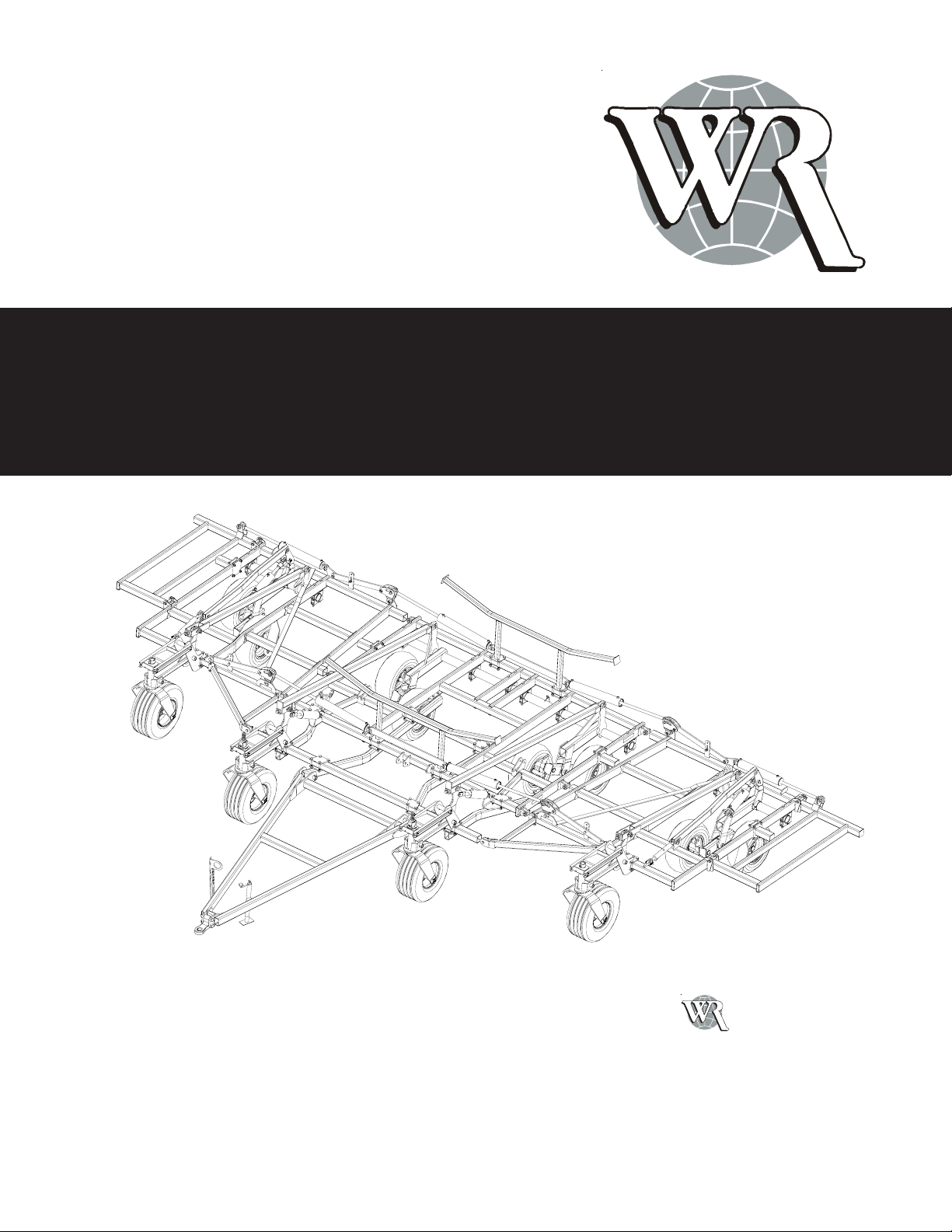
5850 CP OPERATOR’S MANUAL (79451) 3/08
8
SAFETY Apersonwhohasnotreadandunderstoodall
operatingandsafetyinstructionsisnotqualified
tooperatethemachine. Anuntrainedoperator
exposesthemselvesandbystanderstopossible
seriousinjuryordeath.
Do not modify the equipment in any way.
Unauthorized modifications may impair the
functionand/orsafetyandcouldaffectthelifeof
theequipment.
ThinkSAFETY! WorkSAFELY!
GENERAL SAFETY BEFORE
OPERATING
Readandunderstandtheoperator'smanualand
allsafetysignsbeforeoperating,maintainingor
adjustingtheChiselPlow.
Reviewsafety related itemswithall operators
annually.
Useextremecarewhenmakingadjustments.
When working under or around the machine,
alwayslowertheChiselPlowtotheground.
Afterservicing,installandproperly secure all
shieldsandguardsbeforeoperating. Removeall
tools, parts, and service equipment from the
machine.
Haveafirst-aidkitavailablefor useshould the
needariseandknowhowtouseit.
Haveafireextinguisheravailableforuseshould
theneedariseandknowhowtouseit.
Clear the area of people and remove foreign
objectsfromthemachinebefore starting and
operating.
Alwayswearrelativelytightandbeltedclothing
toavoid entanglementinmoving parts. Wear
sturdy,rough-soledworkshoesand protective
equipmentforeyes,hair,hands,andhead. Wear
suitableearprotectionforprolongedexposureto
excessivenoise.
INFORMATION
YOUare responsible forSAFEoperation and
maintenanceofyourWil-RichChiselPlow. YOU
mustensurethatanyonewhoisgoingtooperate,
maintain or work around the Chisel Plow be
familiar with the operating and maintenance
procedures and related safety information
containedinthismanual. Thismanualwilltake
youstepbystepthroughyourworkingday,alerts
youto allgoodsafety practicesthat shouldbe
adheredtowhileoperatingthisequipment.
Remember,YOU are the keytosafety. Good
safetypracticesnotonlyprotectyoubutalsothe
people around you. Make these practices a
workingpartofyoursafetyprogram. Becertain
thatEVERYONEoperatingthisequipmentis
familiarwith therecommendedoperating and
maintenanceproceduresandfollowsallsafety
precautions. Mostaccidentscanbeprevented.
Donotriskinjuryordeathbyignoringgoodsafety
practices.
Chisel Plow owners must give operating
instructionstooperatorsandemployeesbefore
allowingthemtooperatethefieldcultivator,and
atleastannuallythereafterperOSHAregulation
1928.57.
The most important safety device on this
equipmentisasafeoperator.Itistheoperator's
responsibilitytoreadandunderstandALLSafety
andOperatinginstructionsinthemanualandto
followthem. Allaccidentscanbeavoided.
!