WIL-RICH XL2 User manual

5-SECASSEMBLY MANUAL74312B 8/11
1
5 SECTION FIELD
CULTIVATORS
ASSEMBLY INSTRUCTIONS
WIL-RICH
PO Box 1030
Wahpeton, ND 58074
PH (701) 642-2621
Fax (701) 642-3372
www.wil-rich.com
Printed in USA (74312B) 8/11

5-SECTIONASSEMBLYMANUAL74312B 8/11 2
WARRANTY
The only warranty Wil-Rich gives and the only warranty the dealer is authorized to give is as
follows:
We warrant products sold by us to be in accordance with our published specifications or those
specifications agreed to by us in writing at time of sale. Our obligation and liability under this
warranty is expressly limited to repairing, or replacing, at our option, within 12 months after date of
retail delivery, any product not meeting the specifications.
We make no other warranty, express
or implied and make no warranty of merchantability or of fitness for any particular purpose.
Our obligation under the warranty shall not include any transportation charges or costs or installa-
tion or any liability for direct, indirect or consequential damage or delay. If requested by us, products
or parts for which a warranty claim is made are to be returned transportation prepaid to our factory.
Any improper use, operation beyond rated capacity, substitution of parts not approved by us, or any
alteration or repair by others in such manner as in our judgment affects the product materially and
adversely shall void this warranty.
No employee or representative is authorized to change this
warranty in any way or grant any other warranty.
Wil-Rich reserves the right to make improvement changes on any of our products without notice.
When warranty limited or not applicable
: Warranty on hoses, cylinders, hubs, spindles, engines,
valves, pumps or other trade accessories are limited to the warranties made by the respective
manufactures of these components. Rubber tires and tubes are warranted directly by the respec-
tive tire manufacturer only, and not by Wil-Rich.
Warranty does not apply to any machine or part which has been repaired or altered in any way so
as in the our judgment to affect its reliability, or which has been subject to misuse, negligence or
accident.
A Warranty Validation and Delivery Report Form must be filled out and received by Wil-Rich
to initiate the warranty coverage.
WARRANTY CLAIMS PROCEDURE
1. The warranty form must be returned to Wil-Rich within fifteen (15) working days from the repair
date.
2. Parts returned to Wil-Rich without authorization will be refused. The parts must be retained at
the dealership for ninety (90) days after the claim has been filed. If the Service Department would
like to inspect the parts, a packing slip will be mailed to the dealer. The packing slip must be returned
with the parts. The parts must be returned prepaid within thirty (30) days of receiving authorization.
After the parts are inspected and warranty is verified, credit for the return freight will be issued to
the dealer.
3. Parts that will be scrapped at the dealership will be inspected by a Wil-Rich Sales Representa-
tive, District Sales Manager or Service Representative within the ninety (90) day retaining period.

5-SECASSEMBLY MANUAL74312B 8/11
3
ALL PERSONNEL INVOLVED WITH THE ASSEMBLY AND/OR OPERATION OF THIS
EQUIPMENT MUST BE INFORMED OF PROPER SAFETY PROCEDURES. OPERATOR’S/
ASSEMBLYMANUALS PROVIDE THE NECESSARY INFORMATION. IF THE MANUALIS
LOST FOR A PARTICULAR IMPLEMENT, ORDER A REPLACEMENT AT ONCE.
OPERATOR’SANDASSEMBLY MANUALSAREAVAILABLEAT NO CHARGE UPON RE-
QUEST.
PERSONALSAFETY IS IMPORTANT!
ADDRESSINQUIRIESTO:WIL-RICHPOBOX1030
WAHPETON,ND 58074
PH(701) 642-2621 FAX (701)642-3372
This Safety Alert symbol
means ATTENTION! BE-
COME ALERT YOUR
SAFETY IS INVOLVED!
TheSafetyAlert symbol iden-
tifies important safety mes-
sageson theWil-RichQuad X
Field Cultivator and in this
manual. When you see this
symbol, be alert to the possi-
bilityofpersonalinjuryordeath.
Follow the instructions in the
safetymessage.
WhyisSAFETY importanttoyou?
3 Big Reasons Accidents Disable and Kill
Accidents Cost
Accidents Can Be Avoided
SIGNALWORDS:
Note the use of the signal
words DANGER, WARNING
andCAUTION withthe safety
messages. The appropriate
signalword foreachmessage
has been selected using the
followingguidelines:
DANGER
An immediate and spe-
cific hazard which WILL
resultinsevere personal
injury or death if the
proper precautions are
not taken.
WARNING
A specific hazard or un-
safe practice which
COULD result in severe
personal injury or death
if the proper precautions
are not taken
CAUTION
Unsafe practices which
COULD result in per-
sonal injury if proper
practices are not taken,
or as a reminder of good
safety practices.

5-SECTIONASSEMBLYMANUAL74312B 8/11 4
CONTENTS
GENERALINFORMATION ..........................................5
TRANSPORTSAFETY ..................................................6
ASSEMBLY
OPENINGBUNDLE ....................................................7-8
AXLESANDWALKINGTANDEM ................................9
13’ MAINFRAME .......................................................10
13’HITCHASSEMBLY................................................ 11
HITCHASSEMBLY CONTINUED ..............................12
11’8”&9’4” INNERWING ........................................13
INNERWINGHINGE ...................................................14
OUTERWING ..............................................................15
OUTERWINGHINGE ..................................................16
PARALLELLINKGUAGEWHEEL .............................17
DEPTHGAUGE ............................................................18
SINGLEPOINTDEPTHCONTROL ...........................19
SINGLEPOINTHANDLE ............................................20
CHECKVALVE .............................................................21
HOSECLAMP .............................................................22
LIFTHYDRAULICS
XL246 ...........................................................................23
XL250 ...........................................................................24
XL255 ...........................................................................25
WINGFOLD HYDRAULICS
XL246 ...........................................................................26
XL250 & 55 .................................................................27
CHARGINGLIFTSYSTEM .........................................28
CHARGINGWINGFOLDSYSTEM............................29
SHANKPLACEMENTS
TWINSPRINGSHANK ASSEMBLY .........................30
SINGLESPRINGSHANK ASSEMBLY ......................31
13’MAINFRAME ........................................................32
11’8”WING .................................................................33
9’4”INNERWING .......................................................34
9’4”OUTERWING ......................................................35
7’OUTERWING ..........................................................36
HDAUXILIARYHITCH ...............................................37
SAFETYDECALPLACEMENT ............................. 38-39
LIGHTS ........................................................................40

5-SECASSEMBLY MANUAL74312B 8/11
5
GRADE 2 GRADE 5 GRADE 8
TORQUE IN FOOT POUNDS
BOLT DIA 3/8 1/2 5/8 3/4 7/8 1
HEX HEAD 9/16 3/4 15/16 1-1/8 1-5/1 1-1/2
UNC GR2 18 45 89 160 252 320
UNC GR5 30 68 140 240 360 544
UNC GR8 40 100 196 340 528 792
UNF GR2 21 51 102 178 272 368
UNF GR5 32 70 168 264 392 572
UNF GR8 48 112 216 368 792 840
When replacing a bolt, use only a bolt of the
same grade or higher. Except in shear bolt
applications, where you must use the same
gradebolt.
Bolts with no markings are grade 2
Grade5bolts furnishedwiththemachine are
identifiedbythreeradiallines on the head.
Grade8bolts furnishedwiththemachine are
identifiedbysixradiallinesonthe head.
AllU-boltsaregrade5.
THISSYMBOLUSEDTOCALLYOURATTEN-
TIONTOINSTRUCTIONSCONCERNINGYOUR
PERSONALSAFETY.
BESURETOOBSERVEANDFOLLOWTHESE
INSTRUCTIONS
Removeallwires and arrangethepartscon-
veniently.
NOTE: Always wear safety glasses or
goggles and be careful when cutting wires
andsteelbandsastheyareundertensionand
willspringback whencut.
Wherevertheterms"left"and"right"areused,
it must be understood to mean from a posi-
tionbehindand facing themachine.
Lubricate all bearings and moving parts as
youproceed andmakesure theyworkfreely.
Loosely install all bolts connecting mating
partsbeforefinal tightening.
Whentighteningbolts, they mustbetorqued
tothepropernumberof foot-pounds as indi-
cated in the table unless specified. It is im-
portantthatall bolts be kepttight.
Onnew machines,allnuts andboltsmust be
recheckedafterafew hours of operation.
ASSEMBLY INFORMATION
Refer to Operator's Manual for safety instructions.
Do not stand or climb on machine when operating.
Use clean hazard flashers and SMV sign when
transporting.
Observe highway traffic regulations.
TO AVOID INJURY AND/OR MACHINE DAMAGE:
CAUTION
23325
FAILURE TO FOLLOW THESE
INSTRUCTIONS MAY RESULT IN PERSONAL
INJURYAND/OR EQUIPMENT DAMAGE.
CAUTION
53334
Just before and during
operation be sure no one is
on or around the
implement.
Before activating the
hydraulic system, check
hoses for proper
connections.
With wings down always
install hydraulic cylinder
channel lock(s) for
transporting.
Before lowering the wings for
the first time, make sure the
entiresystemhasbeen charged
withoil.
MODIFICATIONS
Itisthe policy ofWil-Richtoimprove its prod-
uctswheneverpossibleandpracticaltodoso.
We reserve the right to make changes, im-
provements and modifications at any time
without incurring obligation to make such
changes, improvements on any equipment
soldpreviously.
5-SECTIONASSEMBLYMANUAL74312B 8/11 6
SAFETY The safety chain should be hooked long
enoughtopermitfullturns.Unnecessaryslack
shouldbetaken up.
Intermediate support is to be used if there is
more than 6" of unsupported chain on either
sideoftheprimary attaching point.
The intermediate support should not be
mounted more than 6" from the primary at-
tachingpoint.(Seefigure below)
The intermediate support is available from
yourWil-Richdealer.
SMVMOUNTINGBRACKET
SMV EMBLEM
NYLONTIE WRAP CI-77643
Thebracketprovidedisdesignedtomountto
numerousframesizes and canbeorientated
indifferentpositionstoavoidinterferencewith
implementcomponents.
TheSMVemblem istobe securedasnearto
therearand centered,orasnear to theleftof
centerofimplementas practical.
Emblemistobe 2 to 6 feetabovetheground
measuredfromtheloweredgeoftheemblem.
Keepsafetydecalsclean.Replaceanysafety
decals that are damaged, destroyed, miss-
ing, painted over or can no longer be read.
Replacement safety decals are available
throughyourdealer.
Thepurposeofthesafetychainis to provide
anauxiliaryattachingsystemtoretainthecon-
nection between towing and towed machine
in the event of separation of the primary at-
tachingsystem.
1/4NCx3/4BOLT
SAFETYCHAIN
CLEVISEND TO
TRACTOR
SAFETYCHAIN
MOUNT
CI-77825
PRIMARYATTACHINGPOINT
INTERMEDIATE
SUPPORT
6"MAX

5-SECASSEMBLY MANUAL74312B 8/11
7
OPENING BUNDLE
Step #1
Laybundledown,supporting frame securely
36to40inchesoff the ground.
Step #2
Unfoldfrontframe and boltintoplaceusing
3/4x2inchgrade8bolts as shown on main
frameandwingassembly pages.

5-SECTIONASSEMBLYMANUAL74312B 8/11 8
OPENING BUNDLE
Step #3
After bundle is unfolded and the two frame
halves are bolted together remove shipping
standsandbrackets.
After the shipping stands and brackets are
removedtherestofthe cultivator may be as-
sembledasshowninthisbook.
Remove
shippingstands
Remove
shippingbrackets

5-SECASSEMBLY MANUAL74312B 8/11
9
MAIN AXLE & WALKING TANDEM
79144.PLT
NOTE: WING WALKING
TANDEM COMPONENTS
ARE THE SAME AS THE
MAINAXLEWALKINGTAN-
DEM.
AXLE & WALKING TANDEM 7’, 9’4” & 11’8” WINGS
PIN1x6-3/8
(68033)
1”FLAT
WASHER
(88196)
ROLLPIN
1/4x2-1/4
(42484)
3/4NCx2-3/4GR5
BOLT-(88841)
WINGAXLEASSY
OUTER
LH -(220782)
RH-(220781)
INNER
LH-(221169)
RH-(221168)
10.8WING MAST
ANCHOR
(221261)INNERWING
9.3WING
MASTANCHOR
(221260)OUTERWING
19-7/8(INNER)
WALKER ASSY
LH -(61631)SHOWN
RH-(61833)
19-1/2(OUTER)
1.75BOREBRG CONE
(25580)
SEAL
(26120)
TANDEMPIN
(16277)
1-1/2NFHYDRALOCK NUT
(42082)
RIGHTHD WALKERASSY
5SEC - (221348)
LEFT HD WALKERASSY
5SEC - (221347)
WHEEL ASSY
2-1/2”HUB
&SPINDLE
(16154)
5/8NCx4GR5
BOLT
(88298)
3/4NCx2-3/4GR5
BOLT
(88841)
MAINAXLE
(220778)
PIN1x6-3/8
(68033)
1”FLAT
WASHER
(88196)
ROLLPIN
1/4x2-1/4
(42484)
BEARINGBUSHING
(12103)
5/8NCLOCK
NUT(88369)
12.6MASTANCHOR
(221262)
22-1/4

5-SECTIONASSEMBLYMANUAL74312B 8/11 10
MAIN FRAME
700402
WINGREST
(240818)
12.6HYD CYL
(67683F1)
PIN1X2-3/8
(42473)
U-BOLT5/8X3X5-1/4
(88503)
PIN(1-1/4x3.38)
(68034)
WASHER FLAT 1”
(88196)
PIN1X6-3/8
(68033)
MASTTUBE
(67707)
3/4NCX 2-3/4GR5BOLT
(88841)
3/4NCx2 GR8BOLT
(88290)
MACHINERYBUSHING
1-1/4IDx1-7/8ODx14GA
(88440)
MACHINERYBUSHING
1-1/4IDx1-7/8ODx14GA
(88440)
PIN(1-1/4x3.38)
(68034)
5X30HYDCYL
(20966F)
PIN1X2-3/8
(42473)
ASSY HDWR
74302-1

5-SECASSEMBLY MANUAL74312B 8/11
11
HITCH ASSEMBLY
79149-2
ADJUSTERASSEMBLY
(68036)
ADJUSTMENTSCREW
(68026)
CENTERHITCHBRACKET
(67937)
1-1/4NCJAMNUT
(88622)
XL2MAINFRAME
HITCH(233672)
PIN(1-1/4ODx5.13)
(68031)
MACHINERYBUSHING
1-1/4x1-7/8x14GA
(88440)
PIN(1-1/4ODx7.25)
(68032)
1-1/4NCx6-1/2GR5BOLT
(88349)
1-1/4NCJAMNUT(2)
(88622)
3/4NCx6GR5BOLT
(88293)
1/4x2-1/4SPIROLPIN
(42484)
4HOLEPLATE
(3.75X4.69)
DIAMOND
(68040) 5/8NCx3
x5-1/4U-BOLT
(88503)
RIGHTHITCHTUBE
(220795) 3/4NCx5GR5
BOLT
XL2MAINFRAMEAXLE(221465)
PIN(1-1/4x3.38)
(68034)
PIN(1-1/4x5.13)
(68031)
LIFTSIDEPLATE
(67933)
4HOLEPLATE
(3.5X4.75)
1-1/2ODx1-1/4IDSPRING
TENSIONBUSHING
(33535)
1 FLAT WASHER
(88196)
PIN(1x6.38)
(68033)
1/4x2-1/4
SPIROLPIN
(42484)
LINKAGE
(67906)
5/8NCx2GR5BOLT
(88294)
LEFTHITCH
TUBE
(220796)
HITCHTUBE
(220792)
XL2CENTER
LIFTTUBE
(67743)
PIN(1-1/4x6-1/8)
(68030)
ASSY HDWR
74302-2

5-SECTIONASSEMBLYMANUAL74312B 8/11 12
HITCH ASSEMBLY CONTINUED
SAFETYCHAIN
(24459)
JACK
(24415)
3/8NCx5x4U-
BOLT(89069)
3/8FLAT
WASHER
(88282)
3/8LOCK
WASHER
(88362)
3/8NCHEX
NUT
(88103)
HITCHBOLT
(11638)
DUALHITCH
(18236)
1-1/4SLOTTED
NUT(88350)
3/16x2COTTER
PIN(88133)
1/4FLAT
WSAHER
(88261)
1/4NCx3/4
GR5BOLT
(88993)
TUBEAND
TUBE
HOLDER
(234313) UTILITY
POLE
(236142)
LIGHTPLUG
RETAINER
(223329)
1/4LOCK
WASHER
(88262)
1/4NCNUT
(88172)
1/4NCx1GR5
BOLT(88203) RUBBER
EDGING
(236092)
700160

5-SECASSEMBLY MANUAL74312B 8/11
13
ANCHORSTRAP
(221693)
3/4NCx13GR5
(88165)
INNER WING
AXLECLAMP
(34132)
WINGTUBE
(221504)
5/8NCx3x5-1/4
U-BOLT
(88503)
PLATE
(241810)
5/8NCx3-1/2GR5
(88292)
INNERWING
STOP
(221358)
OUTER
WING
REST
(221356)
3/4NCx2GR8
(88290)
1NCx2-1/2GR5
(88293)
1NCNLK
(89075)
SEE PAGE
17
3/4 LK
WASHER
(88130)
5/8NCx1-1/2
(88577)
SEE PAGE
22
WINGADJUST
ARM(67709)
NOTE:WING STOPLOCATINGDIMENSIONSARE
APPROXIMATE. SPECIALCARESHOULDBE
TAKENTHE FIRSTTIMETHEWINGSAREFOLDED.
WINGSTOPLOCATIONSMAYREQUIRE ADJUST-
MENT.
700412
5/8NCx3x5-1/4
U-BOLT
(88503)
3/4NC
NUT
(88110)
ASSY HDWR
74305-2
30-3/4
(4PL)
18-1/4
LEFTHINGE
ASSEMBLY
(221499)SHOWN
RIGHTHINGE
ASSEMBLY
((221498)
LEFTHINGE
ASSEMBLY
(221068)SHOWN
RIGHTHINGE
ASSEMBLY
(221067)
5-SEC11’8”FRONTLH
240823(SHOWN)
5-SEC11’8”FRONTRH
240822
5-SEC9’4”FRONTLH
243671
5-SEC9’4”FRONTRH
243672
5-SEC11’8”LH
240821 (SHOWN)
5-SEC11’8” RH
240820
5-SEC9’4” LH
243670
5-SEC9’4” RH
243669

5-SECTIONASSEMBLYMANUAL74312B 8/11 14
INNER WING HINGE
700700
1NCNLK
(89075)
WINGLINK STRAP
(245306)
5/8NCx1-3/4GR5
(88838)
LIFTLINKARM
(233370)63-1/8”
(242870)34-1/4”
1NCx6GR5
(88264)
1NCx4--1/2GR5
(88580)
INNERWING FOLDSTOP
(221358)
1NCx3-1/2GR5
(88447)
WINGLIFTBUSHING
(48523)
WINGLIFTLINK
(221267)
1NCNLK
(89075)
1NCNLK
(89075)
30-3/4

5-SECASSEMBLY MANUAL74312B 8/11
15
OUTER WING
SEE PAGE
17
1NCx2-1/2GR5
(88393)
5SECOUTER
WINGHINGE
(222848)RH
(222849)LH
3/4NCx2-1/2GR5
(88404)
5/8NCx3x5-1/4
U-BOLT
(88503) 3/4NCx2GR8
(88290) 3/4 LK
WASHER
(88130)
3/4NC
NUT
(88110)
3/4NCx13GR5
(88165)
WINGADJUST
ARM(67709)
AXLECLAMP
(34132)
ASSY HDWR
74305-3

5-SECTIONASSEMBLYMANUAL74312B 8/11 16
RIGHTLATCH
(221695) RH
(221696) LH
1”x4-1/4”PIN
(221692)
OUTERWINGLINK
(221189)
3/8”NCx2”GR5BOLT
(89011)
WING ARM
(221190)
1” FLAT WASHER
(88196)
1”NCx 9-1/2” GR5
BOLT
(88901)
1-1/2”x9-1/2”
EXTENSION
SPRING
(25863)
3/8”LOCKNUT
(88162)
OUTER WING HINGE
1/4”x1-1/2”
ROLLPIN
(42484)
1”NCx6” GR5
BOLT
(88264)
1”NC NYLON
LOCKNUT
(89075)
79200-3
5/8”NCX4”X5-1/2”
U-BOLT
(88145)
SHANKSPACER-USEDTO
SPACE SHANK FORWARD TO
CLEARBOLT
(236400)

5-SECASSEMBLY MANUAL74312B 8/11
17
PARALLEL LINK GAUGE WHEEL
700429
GAUGEWHEEL
PIVOTBRACKET
(220850)
3/8NCHEX
NUT
(88103)
3/8LOCK
WASHER
(88362)
CASTERWHEEL
LEG(240360)
PIVOTBOLT
1x6.88
(221336)
LOWERGAUGE
WHEELARM.
(222961)
UPPERGAUGE
WHEELARM
(221100)
5/8NCx3x5-1/4
GR5U-BOLT
(88503)
1NCx6
GR5BOLT
(88264)
GAUGEWHEEL
MOUNT(220853)
5/8NCx4x3-1/4
GR5U-BOLT
(88388)
1NCNYLON
LOCKNUT
(89075)
STOP
COLLAR
(14189)
3/8NCx3
GR5BOLT
(88531)
ASSY HDWR
74302-8
ADJUSTER
ROD(9.5)
(69799)
1-1/4”NC
JAMNUT
(88622)
ADJUST-
MENTROD
(48890) 1”NCNUT
(88125)
BREAK ASSY
(242216)

5-SECTIONASSEMBLYMANUAL74312B 8/11 18
DEPTH INDICATOR
DEPTH
GAUGE
(69303)
DEPTH
INDICATOR
ARM
(69309) 3/8 NC
LOCK NUT
(88162)
ANGLE
(69310)
3/8X3/4
HEX BOLT
(88566)
4-1/2 EXHAUST
CLAMP
(69314)
3/8LK
WASHER
(88362)
3/8 NC NUT
(88103)
U-BOLT 3/8X4X3-3/4
(88514)

5-SECASSEMBLY MANUAL74312B 8/11
19
ADP 8MORB X
8MJ (24024)
PORT 2
ADJUST EAR
(222107)
1/2 JAM NUT
(88561)
700098
SINGLE POINT DEPTH CONTROL
REAR VIEW
FRONT VIEW
HOSE 1/2 X 30 8FJX-8FJX
(242448)
TEE 8MJ X 8MJ
X8MJ
(13238)
CHECK VALVE
(241317)
SINGLE PT TUBE-SHORT
BENT TUBE
5/8 X 3NC HEX
BOLT
(88408) 5/8 NC LOCK
NUT (88369)
1/2 X 2-1/4 NC
HEX BOLT
(88825)
1/2 NC LOCK
NUT (88363)
5/8 NC LOCK
NUT (88369)
5/8 X 1-3/4 NC
HEX BOLT
(88838)
SINGLE
POINT
BRACKET
(238638)
SINGLE
POINT VALVE
(247429)
5/16 NC
LOCK NUT
(88540)
5/16 X 4-1/2
NC HEX BOLT
(88812)
ADP 8MJ X 8MORB
(24024)
ELB 8MJ X
8MORB (25580)
SPACER
TUBE
(238637)
VALVE
SPACER
(238636)
3/16 X 1-3/4
ROLL PIN
(89078)
PLUNGER
(222180)
SLIDE
ADJUST
(222111)
1/2 JAM
NUT
(88621)
(2 JAM
FORWARD)
1/4 X 2-1/2
ROLL PIN
(88767)
ADJUSTMENT
CRANK
(222182)
RETURN LINE
FROM WING LIFT
CYLINDERS
1/4 X 1 NC
HEX BOLT
(89058)
TO BASE END
OF12.6” MAIN
FRAME LIFT
CYLINDER
700418
ASSY HDWR
74302-9
ADP 8MORB X
8FJIC (24004)
PORT 1

5-SECTIONASSEMBLYMANUAL74312B 8/11 20
HANDLE ASSEMBLY
JAM NUTS
TOGETHER
HANDLE SHOULD
ROTATE FREELY
AFTER ASSMELBY
BOTTOM NUT
OUT ON
THREADS
NUT SHOULD BE
POSITIONED FOR-
WARD
Table of contents
Other WIL-RICH Farm Equipment manuals

WIL-RICH
WIL-RICH 2510 User manual

WIL-RICH
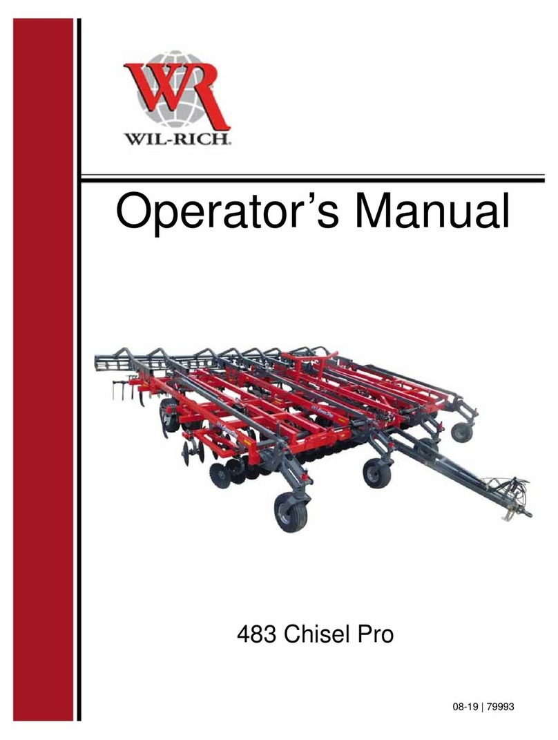
WIL-RICH 483 Chisel Pro User manual

WIL-RICH
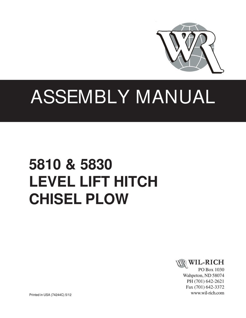
WIL-RICH 5810 User manual

WIL-RICH
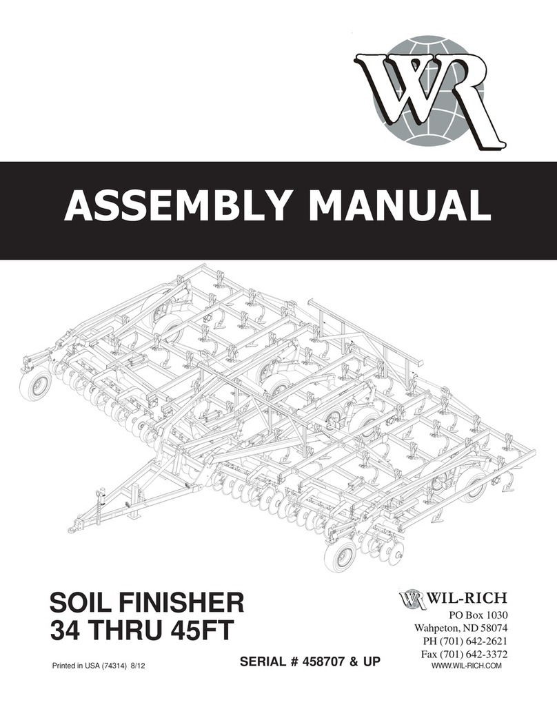
WIL-RICH SOIL FINISHER 34FT User manual

WIL-RICH
WIL-RICH PT2200 FWD User manual

WIL-RICH
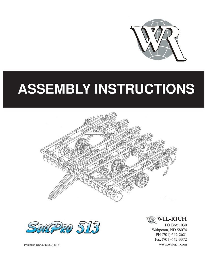
WIL-RICH SoilPro 513 User manual

WIL-RICH
WIL-RICH SoilPro 513 User manual

WIL-RICH
WIL-RICH 657 DISC CHISEL User manual

WIL-RICH
WIL-RICH 483 Chisel Pro User manual

WIL-RICH
WIL-RICH 5850 User manual