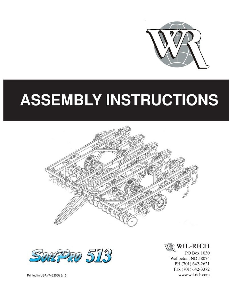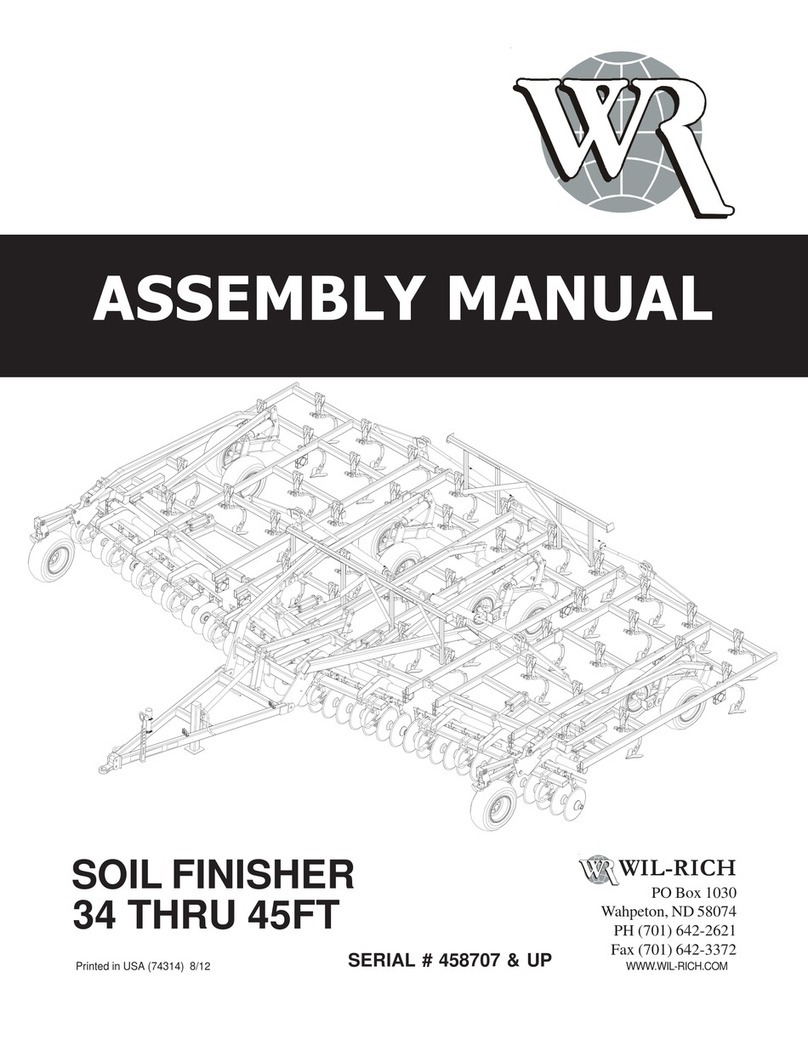
RIGID (16’ & 19’) 483 CHISEL PRO
1. Assembly
Assembly Introduction ............................................................................................................. 5
Main Axle Assembly .................................................................................................................. 8
Shank Assembly......................................................................................................................... 9
16’Shank Frame Layout ........................................................................................................ 10
19’ Shank Frame Layout........................................................................................................ 11
Gang and Axle Spacing.......................................................................................................... 12
Main Frame Assembly to Shank Frames.......................................................................... 13
Main Frame Assembly to Axle and Disc Frames............................................................ 14
Hitch Assembly ......................................................................................................................... 15
Manual Holder Assembly....................................................................................................... 17
Gauge Wheel Assembly......................................................................................................... 18
Gauge Wheel Spindle & Tire Assembly ............................................................................ 19
Disc Lift Assembly.................................................................................................................... 20
Adjust Arm Assembly .............................................................................................................. 21
Single Point Depth Control .................................................................................................... 22
Main Frame Shank Stub Assembly .................................................................................... 23
Main Lift Hydraulics ................................................................................................................. 24
Disc Lift Hydraulics .................................................................................................................. 25
Safety Light Assembly ............................................................................................................ 26
Branding Decal Layout ........................................................................................................... 27
Chrome Straight Spike Assembly........................................................................................ 28
Straight Spike Assembly ........................................................................................................ 29
Concave Twist Spike Assembly........................................................................................... 30
16’ Twisted Spike Layout....................................................................................................... 31
19’ Twisted Spike Layout....................................................................................................... 32
General Information
Orientation:
Any reference to left (L) or right (R) sides or components is to
be understood as being viewed from behind the implement and
looking forward.
Serial Number Break:
Every Implement has a serial number located on the body of
the frame. These serial numbers are consecutively assigned to
the implements as they are manufactured. To aid in part
ordering, we reference the serial number at the point the
change occurred to provide and accurate means of
determining proper parts.
P357194 – CHASIS GREY
SPRAY CAN
P351481 – RED PAINT
SPRAY CAN
P240799 – 460EP
GREASE
