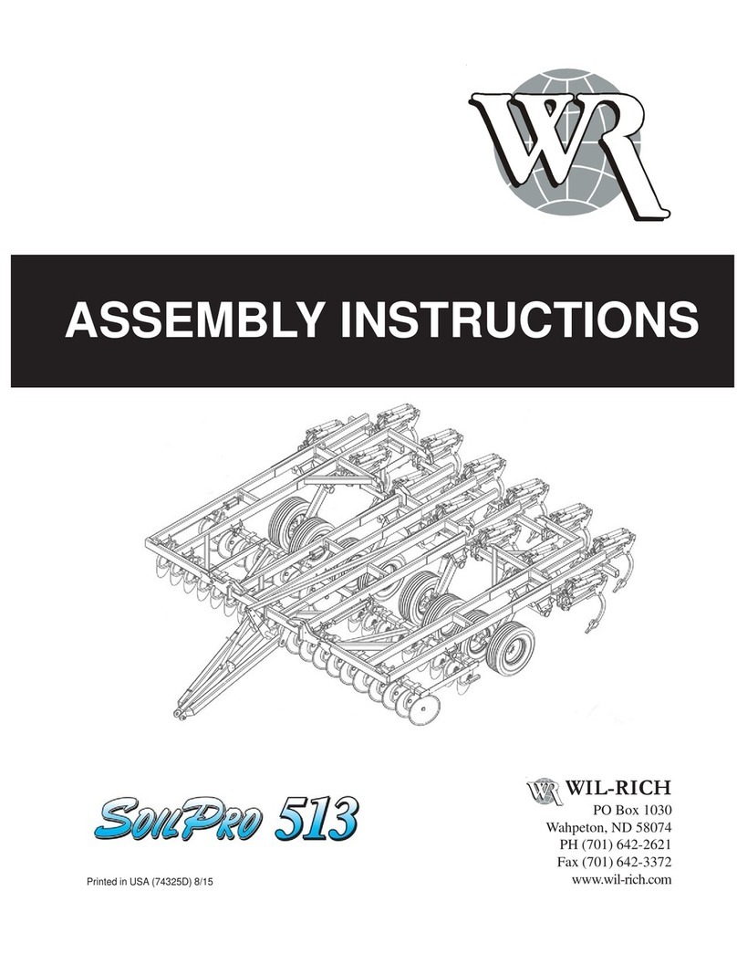
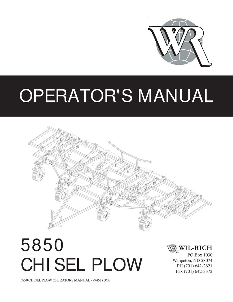
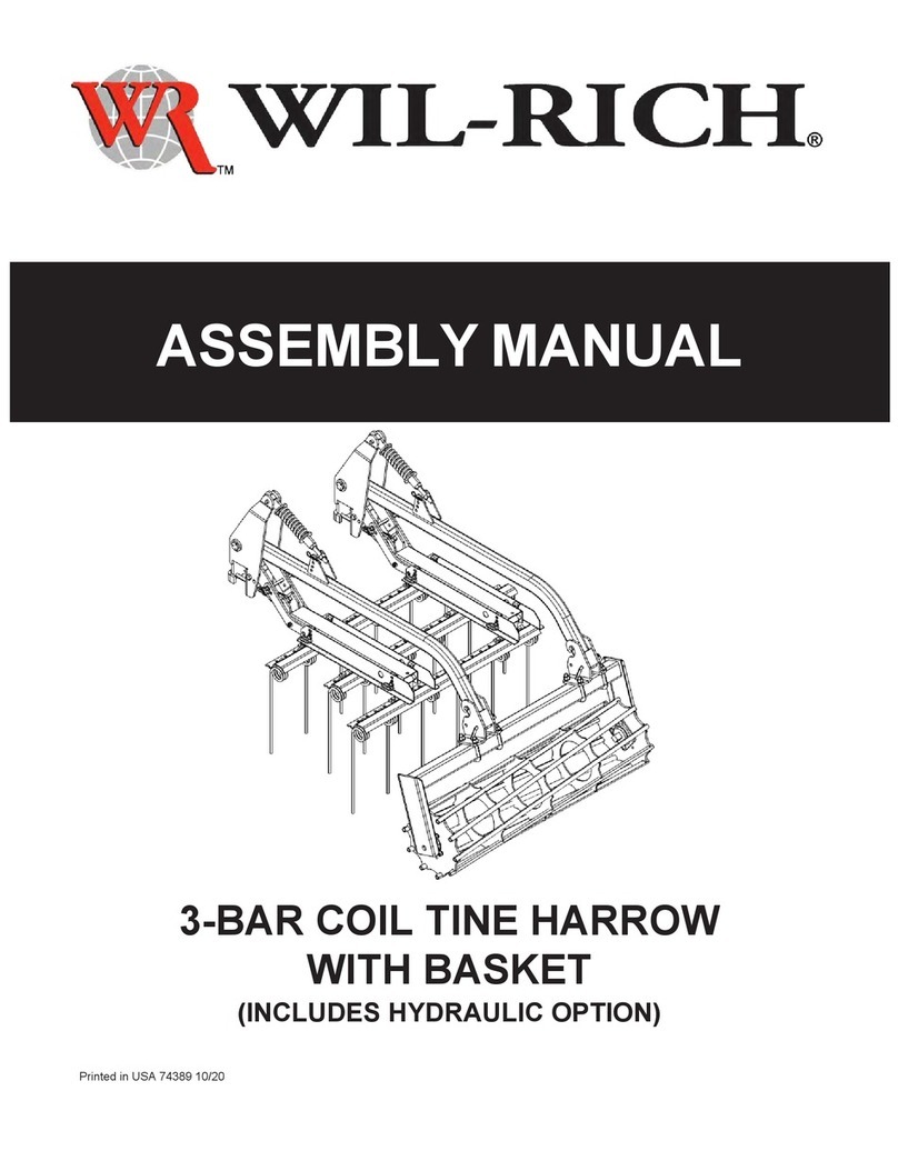
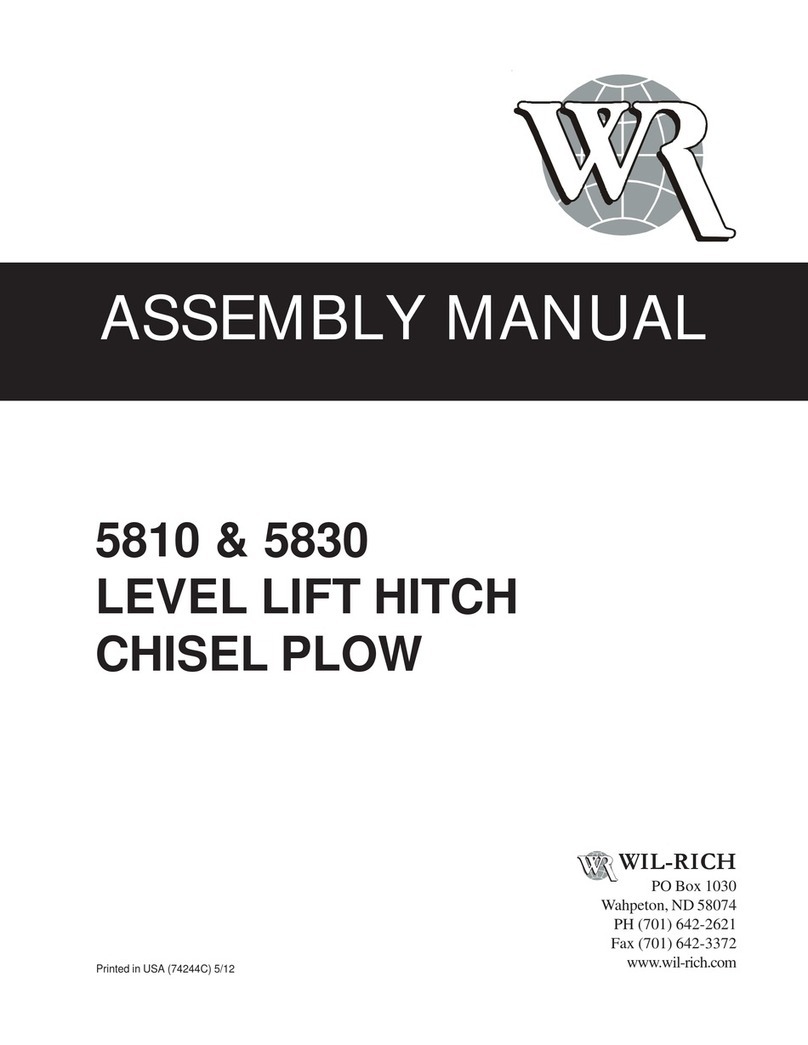
WIL-RICH SOIL FINISHER 34FT User manual

SOIL FINISHER
Printed in USA (74314) 8/12
ASSEMBLY MANUAL
WIL-RICH
PO Box 1030
Wahpeton, ND 58074
PH (701) 642-2621
Fax (701) 642-3372
WWW.WIL-RICH.COM
SERIAL # 458707 & UP
34 THRU 45FT

2
SOILFINISHERASSEMBLYMANUAL(74314)8/12
WIL-RICH, LLC
WARRANTY
Wil-Rich’s products are warranted to the original non-
commercial purchaser to be free from defects in material and
workmanship for a minimum period of twelve (12) months from the original date of purchase.
Additional Field Cultivator Warranty: Wil-Rich warrants to the original purchaser of each newWil-Rich Field Culti-
vator unit (Excel and QuadX), and DiskField Cultivators that the product be free from defects inmaterial and work-
manship for the period of three (3) years on the main frames and shank assemblies. All other components are
covered by the twelve (12) monthwarranty period.
Commercial Use: Warranty for commercial, rental or custom use of any Wil-Rich product is limited to 90 days,
parts and labor.
We warrant products sold by us to be in accordance with our published specifications or those specifications
agreed to by us in writing at time of sale. Our obligation and liability under this warranty is expressly limited to re-
pairing, or replacing, at our option, within12 months after date of retail delivery, any product not meeting the speci-
fications. We make no other warranty, express or implied and make no warranty of merchantability or of
fitness for any particular purpose. If requested by us, products or parts for which a warranty claim is made are
to be returned transportation prepaid to our factory. Any improper use, operation beyond rated capacity, substitu-
tion of parts not approved by us, or any alteration or repair by others in such manner as in our judgment affects the
product materially and adversely shall void this warranty. No employee or representative is authorized to
change this warrantyin any way or grantany other warranty.
Wil-Rich reserves the right to make improvement changes on any of our products without notice.
When warranty limited or not applicable: Warranty on hydraulic hoses, hydraulic cylinders, hubs, spindles, en-
gines, valves, pumps or other trade accessories are limited to the warranties made by the respective manufactures
of these components. Rubber tires and tubes are warranted directly by the respective tire manufacturer only, and
not by Wil-Rich.
This warranty shall not be interpreted to render Wil-Rich liable for injury or damages of any kind or nature to per-
son or property. This warranty does not include claims for, or extend to the loss or damage of crops, loss because
of delay in seeding/planting or harvesting, or any expense or loss incurred for labor, substitute machinery, rental,
and transportation expense or for any other reason.
A Warranty Validation and Delivery Report Form must be filled out and received by Wil-Rich to initiate the
warranty coverage.
WARRANTY CLAIMS PROCEDURE
1. The warranty form must be returned to Wil-Rich within thirty (30) working days from the repair date.
2. Parts returned to Wil-Rich without authorization will be refused. The parts must be retained at the dealership for
ninety (90) days after the claim has been filed. If the Service Department would like to inspect the parts, a packing
slip will be mailed to the dealer. The packing slip must be returned with the parts. The parts must be returned pre-
paid within thirty (30) days of receiving authorization. After the parts are inspected and warranty is verified, credit
for the return freight will be issued to the dealer.
3. Parts that will be scrapped at the dealership will be inspected by a Wil-Rich Sales Representative, District Sales
Manager or Service Representative within the ninety (90) dayretaining period.
3SOILFINISHERASSEMBLYMANUAL(74314)8/12
CONTENTS
GENERAL INFORMATION................. 4&5
SAFETY EQUIPMENT.............................. 6
OPENING FRAME BUNDLE.......... 7,8 & 9
MAINAXLE .............................................. 10
MAIN AXLE & MAST TUBES ................. 11
MAINFRAME RAIL SUPPORTS 42&45 . 12
10FT WING TANDEM AXLE ................... 13
10FT WING ASSEMBLY ......................... 14
4FT OUTER WING ................................. 15
RIGID GAUGE WHEEL 4FT WING ........ 16
MAINFRAME DISC GANGS ................... 17
10FT WING DISC GANG ........................ 18
4FT WING DISC GANG .......................... 19
MAIN POLE ASSEMBLY ........................ 20
MAIN HITCH & LEVEL LIFT ASSY ........ 21
LEVEL LIFT ASSY CONTINUED ........... 22
UTILITY POLE........................................ 23
WING REST ............................................ 24
WING REST 4FT OUTER WING............ 25
WING LIFT COMPONENT 34&37FT..... 26
WING LIFT COMPONENT 42&45FT..... 27
WING CASTERING GAUGE WHEEL .... 28
TWIN SPRING SHANK ASSEMBLY ...... 29
SINGLE SPRING SHANK ASSEMBLY.. 30
REAR HITCH........................................... 31
DEPTH GAUGES MF & DG .............. 32,33
SINGLE POINT DEPTH CNTL .34,35 & 36
CHARGING LIFT & FOLD SYTM ..... 37,38
HOSE CLAMP ASSEMBLY .................... 39
DEPTH CONTROL HYD34,37,42&45 ... 40
WING FOLD HYD 34 & 37FT ................. 41
WING FOLD HYD 42 & 45FT ................. 42
DISC LIFT HYD 34 & 37FT .................... 43
DISC LIFT HYD 42 & 45FT .................... 44
MAINFRAME SHANK PLACEMENT...... 45
SHANK PLACEMENT 10FT WING ........ 46
SHANK PLACEMENT 10FT WING ........ 47
SHANK PLCMNT 4FT OUTER WING ... 48
SHANK PLCMNT 4FT OUTER WING ... 49
DECALS ............................................. 50,51
LIGHTS ................................................... 52

4
SOILFINISHERASSEMBLYMANUAL(74314)8/12
ALL PERSONNEL INVOLVED WITH THE ASSEMBLY AND/OR OPERATION OF THIS
EQUIPMENT MUST BE INFORMED OF PROPER SAFETY PROCEDURES. OPERATOR’S/
ASSEMBLY MANUALS PROVIDE THE NECESSARY INFORMATION. IF THE MANUAL
IS LOST FOR A PARTICULAR IMPLEMENT, ORDER A REPLACEMENT AT ONCE.
OPERATOR’SANDASSEMBLYMANUALSAREAVAILABLE AT NO CHARGE UPON RE-
QUEST.
PERSONALSAFETYIS IMPORTANT!
ADDRESSINQUIRIESTO:WIL-RICHPOBOX1030
WAHPETON,ND58074
PH(701)642-2621 FAX(701) 642-3372
This Safety Alert symbol
means ATTENTION! BE-
COME ALERT YOUR
SAFETY IS INVOLVED!
TheSafetyAlert symbol iden-
tifies important safety mes-
sagesontheWil-RichSoil Fin-
isherandinthismanual. When
you see this symbol, be alert
to the possibility of personal
injury or death. Follow the in-
structions in the safety mes-
sage.
Whyis SAFETYimportant toyou?
3 Big Reasons Accidents Disable and Kill
Accidents Cost
Accidents Can Be Avoided
SIGNALWORDS:
Note the use of the signal
words DANGER, WARNING
andCAUTION with thesafety
messages. The appropriate
signalwordfor each message
has been selected using the
followingguidelines:
DANGER
An immediate and spe-
cific hazard which WILL
resultin severepersonal
injury or death if the
proper precautions are
not taken.
WARNING
A specific hazard or un-
safe practice which
COULD result in severe
personalinjuryordeathif
the proper precautions
arenot taken
CAUTION
Unsafe practices which
COULDresultinpersonal
injury if proper practices
are not taken, or as a re-
minder of good safety
practices.

5SOILFINISHERASSEMBLYMANUAL(74314)8/12
GENERAL INFORMATION
GRADE 2 GRADE 5 GRADE 8
TORQUE IN FOOT POUNDS
BOLT DIA 3/8 1/2 5/8 3/4 7/8 1
HEX HEAD 9/16 3/4 15/16 1-1/8 1-5/16 1-1/2
UNC GR2 18 45 89 160 252 320
UNC GR5 30 68 140 240 360 544
UNC GR8 40 100 196 340 528 792
UNF GR2 21 51 102 178 272 368
UNF GR5 32 70 168 264 392 572
UNF GR8 48 112 216 368 792 840
TORQUE.EPS
WHEEL BOLTS
It is recommended that all wheel bolts be
checkedfor tightness before usingand again
afterone dayof use. Checkperiodicallyto be
surethe wheelbolts aretight.
LUBRICATION
Make sure the Soil Finisher is properly lubri-
cated.
HYDRAULICS
Checkwing liftanddepth controlcylinders for
properalignment and operation. On anyma-
chine, check that the hydraulic system has
beenproperly charged andpurged.
When tightening bolts, they must be torqued
to the proper number of foot-pounds as indi-
catedinthetableunless specified. Itis impor-
tantthat allboltsbe kepttight.
Onnew machines, all nuts and bolts must be
recheckedafter a fewhoursof operation.
When replacing a bolt, use only a bolt of the
samegradeorhigher.Exceptinshearboltap-
plications,whereyoumustusethesamegrade
bolt.
Bolts with no markings are grade 2
Grade5 bolts furnished with themachineare
identifiedby three radial linesonthe head.
Grade8 bolts furnished with themachineare
identifiedby six radial lines onthehead.
AllU-boltsare grade 5.
TIRE INFLATION
Theuse ofproperair pressureisthe mostim-
portantfactorinsatisfactoryperformanceand
maintenanceofimplementtire. Underinflation
willdamagethecordbodyofthetireandcause
a series of diagonal breaks in the fabric
sidewallarea.
Ifthe tire bucklesor wrinkles, theairpressure
must be increased to the point where the
sidwallremains smoothwhileoperating.
Check the air pressure every two or three
weeks and do not allow the pressure to drop
to a point where buckling or wrinkling of the
tire may be possible.
Note: Do not inflate tires beyond the
specified tire pressure.

6
SOILFINISHERASSEMBLYMANUAL(74314)8/12
SAFETY
Thesafetychainshouldbehookedlongenough
topermit fullturns. Unnecessaryslackshould
betaken up.
Intermediate support is to be used if there is
more than 6" of unsupported chain on either
sideof the primaryattachingpoint.
The intermediate support should not be
mountedmorethan6"fromtheprimaryattach-
ingpoint. (See figure below)
The intermediate support is available from
yourWil-Rich dealer.
SMVMOUNTING
BRACKET(350933)
SMV EMBLEM
(30651)
79980
Thebracketprovidedisdesignedtomountto
numerousframe sizesandcan beorientated
indifferentpositionsto avoidinterferencewith
implementcomponents.
TheSMV emblemis tobe securedasnearto
therear andcentered,or asnear totheleft of
centerof implement aspractical.
Emblemis to be2to 6 feetabovethe ground
measuredfromtheloweredgeoftheemblem.
Keepsafetydecalsclean.Replaceanysafety
decals that are damaged, destroyed, miss-
ing, painted over or can no longer be read.
Replacement safety decals are available
throughyourdealer.
Thepurposeof the safety chain is to provide
anauxiliaryattachingsystemtoretainthecon-
nection between towing and towed machine
in the event of separation of the primary at-
tachingsystem.
1/4NCx3/4BOLT
(88993)
SAFETYCHAIN
CLEVISENDTO
TRACTOR
SAFETYCHAIN
MOUNT
CI-77825
PRIMARYATTACHINGPOINT
INTERMEDIATE
SUPPORT
6"MAX
U-BOLT3/8NC

7SOILFINISHERASSEMBLYMANUAL(74314)8/12
OPENING BUNDLE
700243B
700243A
Step #1
Unstapfrontandrearwingrests(items237823
&246444.Lay bundledown,supporting frame
securely36 to40inches offtheground.

8
SOILFINISHERASSEMBLYMANUAL(74314)8/12
OPENING BUNDLE
700243C
Step #2
Rotatemainframe(center) disc axlesas
shownbelow.
700243D
Step #3
Unfoldfront frameandbolt intoplace using
3/4x2inch grade 8 boltsasshown on main
frameand wing assembly pages.

9SOILFINISHERASSEMBLYMANUAL(74314)8/12
OPENING BUNDLE
Step #4
After bundle is unfolded and the two frame
halves(front&rear)areboltedtogetherremove
shippingstands and brackets.
Afterthe shippingstands andbrackets arere-
moved the rest of the cultivator may be as-
sembledas shown onthe following pages.
700243E
REMOVE
SHIPPINGSTANDS
REMOVE
SHIPPINGBRACKETS

10
SOILFINISHERASSEMBLYMANUAL(74314)8/12
MAIN AXLE
ASSY HDWR
74334-1
700297
5/16X2-3/4
LYNCHPIN
(915402)
CHNLLOCK 1-1/2"x10"
(220061)
MASTANCHOR
12.6(221262)
4x12.56
HYDCYLINDER
(67683F1)
HEADLESSPIN
1x6-3/8(68033)
1" FLAT WASHER
(88196)
1/4x2-1/4ROLL PIN
42484)
3/4NCx2-3/4 GR5 BOLT
(88841) NUT HEX 3/4NC
(88356)

11 SOILFINISHERASSEMBLYMANUAL(74314)8/12
MAIN AXLE & MAST TUBES
ASSY HDWR
74314-9
700244
MAIN MAST TUBE
(237697)
BUSHING MACHINERY
1-1/4x1-7/8
(88440)
HEADLESS PIN
1-1/4x3.38
(68034)
1/4x2-1/4ROLL PIN
42484)
WHLASSY13.50-15FI 8B 10IN F
(246254)
9/16NFX1-1/8
WHEELBOLT
(63831)
HEADLESS PIN
1x2-3/8
(42473)
4x12.56
HYDCYLINDER
(67683F1)
4x30 HYD CYLINDER
(51229F) 34 & 37FT UNITS
5x30 HYD CYLINDER
(20966F) 42 & 45FT UNITS
3/4NCx2GR8BOLT
(88290)
3/4NCLOCKNUT
(88356)
1/4x2-1/4
ROLLPIN
(42484)

12
SOILFINISHERASSEMBLYMANUAL(74314)8/12
MAINFRAME RAIL SUPPORTS 42 &45FT
ASSY HDWR
74314-22
BACK PLATE-
RAIL CLAMP
(246443)
3/4NCx12GR5BOLT
(88871)
3/4NCLOCKNUT
(88356)
RAIL SUPPORT
(246442)
700298

13 SOILFINISHERASSEMBLYMANUAL(74314)8/12
10.8 MAST ANCHOR
(221261)
NUT HEX 3/4NC
(88356)
4x10.8 HYD CYLINDER
(67688F1)
1/4x2-1/4 ROLL PIN
(42484)
HEADLESSPIN 1x6.38
(68033)
3/4NCx2-3/4 GR5 BOLT
(88841)
10FT WING TANDEM AXLE
ASSY HDWR
74334-7
700248
1/2NFx1WHEELBOLT
(88142)
WHLASSY31X13.5 6B
10"12PGRAY(222087)
HEADLESSPIN 1x2-3/8
(42473)
1" FLAT WASHER
(88196)

14
SOILFINISHERASSEMBLYMANUAL(74314)8/12
ASSY HDWR
74314-5
10FT WING ASSEMBLY
NUTHEX 3/4NC
(88356)
5/8NCx4x5-1/4U-
BOLT
(88145) NUT HEX 5/8NC
(88369)
3/4NCx1-3/4GR5BOLT
(88405)
1/4x2-1/4
ROLLPIN
(42484)
BUSHING MACHINERY
1-1/4x1-7/8
(88440)
HEADLESSPIN
1-1/4x3.38
(68034)
TUBEGAUGE WHEEL-
10FTWING
(237802)
WINGMAST
(237700)
NUTNYLONLOCK1NC
(89075)
1NCx6GR5BOLT
(88264)
GAUGETUBEADJUST
BRACKET
(220843) ADJUSTABLEROD
ASSEMBLY
(48890)
NUT NEX 1NC
(88125)
ADJUSTERROD9.5"
(69799)
TIGHTENJAMNUTAGAINST
FLAT BARTO LOCKAD-
JUSTERROD
NUTJAM1-1/4NC
(88622)
WHEELARM-LH
(237673)-SHOWN
RH(238403)
3/4NCx2GR8BOLT
(88290)
700249

15 SOILFINISHERASSEMBLYMANUAL(74314)8/12
4' OUTER WING
ASSY HDWR
74314-8
700251
1/2NCx1GR5
BOLT
(89015)
SHIM
(51469)
NOTE:
SEE SHANK PLACEMENTS FOR LOCATIONS
OF STUBS. USE THE CORRECT NUMBER OF
SHIMS TO LEVEL WING.
4FTOUTERWING
(246294-LH)
(246438-RH)
HINGEMOUNT
FRONT
(246420-LH)
(246432-RH)
HINGEMOUNT
REAR
(246421-LH)
(246431-RH)
4x30HYDCYLINDER
(51229F)
1/4x2-1/4ROLL PIN
(42484)
HEADLESSPIN 1x2-3/8
(42473)
1NCx5GR5
BOLT
(88312)
LINKAGE ARM
(67903)
PLATE 2 HOLE
(67934)
1" FLAT
WASHER
(88196)
1NCx6GR5BOLT
(88264)
NUTNYLON
LOCK1NC
(89075)
5/8NCx3x5-1/4
U-BOLT
(88503)
5/8NCx4-1/2GR5
BOLT
(88381)
5/8" LOCK
WASHER
(88129)
NUT HEX 5/8NC
(88126)
5/8NCx5x3-1/2
U-BOLT
(89443)
BACK PLATE
(246429)
1/2NCx3-1/2
GR5BOLT
(88507)
BACK PLATE
5"MTG
(65688)
6-1/2SHANK
STUB
(68021)
1/2" LOCK
WASHER
(88303)
NUT HEX 1/2NC
(88104)

16
SOILFINISHERASSEMBLYMANUAL(74314)8/12
ASSY HDWR
74314-10
RIGID GAUGE WHEEL 4FT OUTER WING
1/2NFx1 WHEEL BOLT
(88142)
WHL ASSEMBLY 95Lx15
6B 6" 8P GRAY
(16290)
1-3/4 HUB&SPINDLE
ASSEMBLY (41234)
NUT 2POSLK 1/2NF
(88304)
1/2NFx3-1/4 GR5
BOLT (88429)
GAUGE WHEEL LEG
(15475)
5/8NCx2-1/2x3-3/4 U-BOLT
(88311)
BACK PLATE-GAUGE
WHEEL
(239411)
700950
TOP ADJUSTMENT
ASSY (15485)
BLT HEX 5/8-11NCx4 5Z
(88298)
WSHR HLK 5/8ID
(88129)
NUT HEX 5/8NC
(88126)
1/2NCx3-1/2
GR5BOLT
(88507)
BACK PLATE
5"MTG
(65688)
6-1/2SHANK
STUB
(68021)
1/2" LOCK
WASHER
(88303)
NUT HEX 1/2NC
(88104)
16-1/2SHANK
STUB
(237376)
NOTE:
STUBS USED ON 45FT UNITS ONLY

17 SOILFINISHERASSEMBLYMANUAL(74314)8/12
MAIN FRAME DISC GANG ASSY-RH
(237828 - 10 BLADE)
7/8NCx6 GR5 BOLT
(89021)
ASSY HDWR
74314-11
MAIN FRAME DISC GANGS
PLATE GANG BEAM MOUNT
(238404)
NOTE:
THESPACING BETWEEN
CENTERDISK BLADES
IS 12"AT THE CLOSEST POINT.
EACH GANG IS 6" OUT
FROMCENTER. USE THIS
AS A STARTING POINT.
MAIN FRAME DISC GANG ASSY-LH
(237827 - 10 BLADE)
3-3/4x8 SEQ HYD CYL (25649) 34 & 37FT
3-1/2x8 SEQ HYD CYL (25654) 42 & 45FT
3-1/2x8 SEQ HYD CYL (25654) 34 & 37FT
3-1/4x8 SEQ HYD CYL (25659) 42 & 45FT
700282
7/8NCLOCKNUT
(88836)

18
SOILFINISHERASSEMBLYMANUAL(74314)8/12
10FT WING DISC GANG
3-1/4 x 8 SEQ HYD CYL RH WING(25659) 34 & 37FT
3 x 8 SEQ HYD CYL RH WING(246456) 42 & 45FT
PLATE GANGBEAM MOUNT
(238404)
7/8NCLOCKNUT
(88836) WING DISC GANGASSY LH SHOWN
(237620-LH13 BLADE34, 42& 45FT)
(237832-RH13 BLADE34, 42& 45FT)
(238450-LH15BLADE 37FT)
(238452-RH15BLADE37FT)
7/8NCx6GR5BOLT
(89021)
ASSY HDWR
74314-12
700289
3-3/4 x 8 SEQ HYD CYL LH WING(25649) 42 & 45FT
4 x 8 SEQ HYD CYL LH WING(25643) 34 & 37FT

19 SOILFINISHERASSEMBLYMANUAL(74314)8/12
700252
4x8 SEQ HYD CYL-LH WING(25643)
2-3/4X8 SEQ HYD CYL-RH WING(246455)
7/8NCx6 GR5 BOLT
(89021)
DISC AXLE-
4FT OUTER WING
(246416-LH SHOWN)
(246415-RH)
3/4NCx8 GR5 BOLT
(88403)
AXLE CLAMP ASSEMBLY
(34132)
3/4NC LOCK NUT
(88356)
WING DISC GANG ASSY LH SHOWN
(239422-LH 7 BLADE 45FT)
(239423-RH 7 BLADE 45FT)
(238488-LH 5 BLADE 42FT)
(238489-RH 5 BLADE 42FT)
PLATE GANG BEAM MOUNT
(238404)
7/8NC LOCK NUT
(88836)
DISC GANG 4FT OUTER WING
ASSY HDWR
74314-13

20
SOILFINISHERASSEMBLYMANUAL(74314)8/12
MAIN POLE ASSY
3/4NCx2-1/2
GR5 BOLT
(88404)
3/4NCx6-1/2 GR5 BOLT
(89130)
CLAMP PLATE-PAINTED
(237633)
3/4 LOCK
WASHER
(88130)
3/4NC NUT HEX
(88110)
BRACKET
CENTERLIFT
(237694)
1NCx3 GR5 BOLT
(88399)
MAIN POLE
WELD-LH
(237626)
CROSS TUBE-POLE
CONNECTION
(237534)
CLAMP PLATE-
PAINTED 4x6
(237640)
TUBE FRONT SUP-
PORT
(237641)
1" LOCK
WASHER
(88617)
MAIN POLE
WELD-RH
(237630)
NUT HEX 1NC
(88125)
3/4NCx6-1/2
GR5 BOLT
(89130)
3/4NCx5-1/2
GR5 BOLT
(88579)
ASSY HDWR
74257-2
This manual suits for next models
1
Table of contents
Other WIL-RICH Farm Equipment manuals

WIL-RICH
WIL-RICH 11 XL2 Series User manual

WIL-RICH
WIL-RICH SoilPro 513 User manual

WIL-RICH
WIL-RICH 483 Chisel Pro User manual

WIL-RICH
WIL-RICH PT2200 FWD User manual

WIL-RICH
WIL-RICH 5810 User manual

WIL-RICH
WIL-RICH SoilPro 513 User manual

WIL-RICH
WIL-RICH 483 Chisel Pro User manual

WIL-RICH
WIL-RICH 5850 User manual

WIL-RICH
WIL-RICH 2550 User manual

WIL-RICH
WIL-RICH 657 DISC CHISEL User manual