3061916_0611 9
Display Designation
A : 0 1 ActualDHWtemperature,solarcylinder(°C)
A : 0 2 Max.DHWtemperature,solarcylinder(°C)
A : 0 3 Collectortemperature(°C)
A : 0 4 Maximumcollectortemperature(°C)
A : 0 5 Returntemperature(°C)
A : 0 6 Solarcircuitowrate(l/min)
A : 1 0 Hoursrun,solarcircuitpump(h)
A : 1 2 Currentoutput(kW)
A : 1 3 Currentdayyield(kWh)
A : 1 4 Totalyield(Wh)
A : 1 5 Totalyield(kWh)
A : 1 6 Totalyield(MWh)
A : 1 7 Solarheatingstatus
(0=unsuccessful,1=successful)
Display values used with
SM1 solar module
Subject to the solar module used, different display values are available.
Display Designation
A : 0 1 ActualDHWtemperatureinsolarcylinder1(°C)
A : 0 2 Max.DHWtemperature,solarcylinder1(°C)
A : 0 3 Collectortemperature,collectorarray1(°C)
A : 0 4 Maximumcollectortemperature,collectorarray1(°C)
A : 0 5 InputE1*
A : 0 6 InputE2:solarcircuitowrate(l/min)
A : 0 7 InputE3*
A : 0 8
MaximumDHWtemperature,solarcylinder2(°C)
A : 0 9 Maximumcollectortemperature,collectorarray2(°C)
A : 1 0 Hoursrun,solarcircuitpump1(h)
A : 1 1 Hoursrun,solarcircuitpump2(h)
A : 1 2 Currentoutput(kW)
A : 1 3 Currentdayyield(kWh)
A : 1 4 Totalyield(Wh)
A : 1 5 Totalyield(kWh)
A : 1 6 Totalyield(MWh)
A : 1 7 Solarheatingstatus,cylinder1
(0=unsuccessful, 1=successful)
A : 1 8 Solarheatingstatus,cylinder2
(0=unsuccessful, 1=successful)
A : 1 9 MaximumDHWtemperature,solarcylinder3(°C)
A : 2 0 Hoursrun,solarcircuitpump3(h)
A : 2 1 Solarheatingstatus,cylinder3
(0=unsuccessful,1=successful)
*AssignmentofinputsE1andE3subjecttothecongurationselectedattheSM2.
Display values used with
SM2 solar module
Note:DisplayA19toA21onlyeffectivefromsoftwareversion
SM1/SM2228_04.
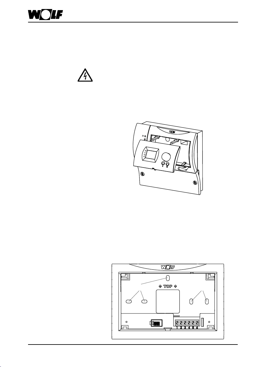
Display level

 Quick start guide")