Table of Contents Section-Page
Table of Contents DS12doc060917 iii
SECTION 5 REPLACEMENT PARTS 5-1
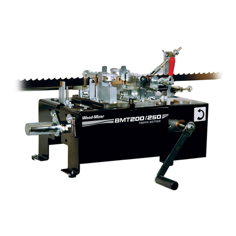
5.1 Dual Toothsetter (Complete)..................................................................................... 5-1
5.2 Dual Toothsetter Assembly ....................................................................................... 5-2
5.3 Base Housing Assembly............................................................................................ 5-3
5.4 Feed Drive Assembly ................................................................................................ 5-5
5.5 Blade Setters.............................................................................................................. 5-7
5.6 Blade Set Arm Assembly .......................................................................................... 5-9
5.7 Clamp Assembly ..................................................................................................... 5-11
5.8 Index Assembly ....................................................................................................... 5-13
5.9 Blade Support Arm Assembly................................................................................. 5-15
5.10 Auto Feed Control, AC 120V (Optional) ................................................................ 5-17
5.11 Auto Feed Control, AC 220V (Optional) ................................................................ 5-19
5.12 Auto Feed Control, DC (Optional).......................................................................... 5-21
5.13 Auto Feed Control Panel, AC (Optional) ................................................................ 5-23
5.14 Auto Feed Motor, AC (Optional) ............................................................................ 5-24
5.15 Auto Feed Motor, DC (Optional) ............................................................................ 5-25
5.16 Toothsetter Gauge Assembly .................................................................................. 5-26
SECTION 6 ELECTRICAL INFORMATION 6-1
6.1 Schematic, AC 120V................................................................................................. 6-1
6.2 Schematic, AC 220V................................................................................................. 6-3
6.3 Schematic, DC........................................................................................................... 6-5
6.4 Component Layout Diagrams (AC Only) ................................................................. 6-6
Front Panel, Control Box.................................................................... 6-6
Insert Panel, Control Box ................................................................... 6-6
6.5 Component Layout Diagrams (DC Only) ................................................................. 6-7
Front Panel, Control Box.................................................................... 6-7
6.6 Component List (AC Only)....................................................................................... 6-8
6.7 Component List (DC Only)....................................................................................... 6-9
INDEX I
