Wopa SA0035 User manual

User Manual
Hoof trimmingcrush:SA0035
Version: 24-09-14
User manual
Hoof trimming crush
SA0035

User manual
Hoof trimmingcrush:SA0035
Version: 24-09-14
Page 2 of 29
Manufacturer:
Wopa Constructiebedrijf BV
Rector Hulshofstraat 10
7135 JV Harreveld
The Netherlands
: +31-(0)544 372415
: +31-(0)544 372445
Email: info@wopa.com
Website: www.wopa.com
© Copyright 2014
No part of this publication may be reproduced, stored in a search system or transferred in any form
whatsoever, either electronically or mechanically, or by photocopying or recording, or in any other way
whatsoever without prior written consent from Wopa Constructiebedrijf BV (hereinafter in this manual
also referred to as “Wopa”).

User manual
Hoof trimmingcrush:SA0035
Version: 24-09-14
Page 3 of 29
Introduction
Wopa Constructiebedrijf BV specialises in development and manufacture of hoof trimming and
treatment crushes for cows and bulls for professional users as well as for cattle farmers.
Our crushes are developed and manufactured in the highest possible quality, according to the strictest
requirements as far as safety, user convenience, animal welfare and hygiene are concerned, always
striving for an optimum.
This manual contains information and instructions relevant to installation, operation and maintenance
of the machine.
The machine is not suitable for use in explosive hazardous environments.
All persons responsible for operation must, at minimum, read and comprehend
the sections on operation and safety of these operating instructions.
All persons responsible for assembly, installation, maintenance and/or repair
must read and comprehend all these operating instructions.
The user is responsible for interpretation and use of this manual under all
conditions. Should you have any doubts or questions regarding the correct
interpretation, please contact the owner or the supervisor.
Keep this manual nearby the installation and within the users' reach.
Keep a log of all major maintenance work, adaptations to the installations and
observations, see Annex 8.1.
Changes to the installation/machine are not permitted without prior written
approval from the supplier.
Contact the supplier for any special maintenance work not included in this
manual.
Comply with the safety requirements as given in Section 3 at all times.
Proper functioning as well as the safety of the system can only be guaranteed
if the recommended maintenance is carried out correctly and on time.

User manual
Hoof trimmingcrush:SA0035
Version: 24-09-14
Page 4 of 29
Warranty
The warranty is subject to the following limitations. The warranty period for products supplied by
Wopa is 12 months from the date on the purchasing document. The warranty is limited to
production and material errors and therefore does not cover any breakdowns due to a part of the
product exposed to any type of wear. Normal wear as can be expected from using this product is
therefore excluded.
1. Wopa’s responsibility remains limited to replacing defective parts; we recognise no claims to
any other type of loss or costs.
2. The warranty is automatically void in case of overdue or poorly implemented maintenance.
3. Should you have any doubts regarding maintenance work or should the machine fail to
operate correctly, contact the supplier.
4. The warranty does not apply if the defect is the result of incorrect or negligent use or of
maintenance carried out contrary to the instructions in this manual.
5. The warranty is void if any repairs or adaptations are made to the product by third parties.
6. Defects ensuing from damage or accidents caused by external factors are excluded from the
warranty.
7. If we replace any parts in accordance with the obligations ensuing from this warranty, the parts
we replaced become our property.

User manual
Hoof trimmingcrush:SA0035
Version: 24-09-14
Page 5 of 29
Table of Contents
INTRODUCTION...............................................................................................................................................3
WARRANTY.....................................................................................................................................................4
TABLE OF CONTENTS....................................................................................................................................5
EC CONFORMITY DECLARATION (COPY)......................................................................................................6
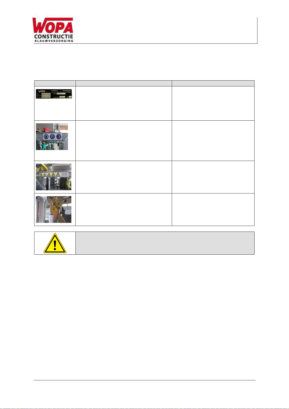
OVERVIEW OF SYMBOLS...............................................................................................................................7
PICTOGRAMS..................................................................................................................................................8
1. TECHNICAL INFORMATION.....................................................................................................................9
2. DESCRIPTION OF THE INSTALLATION.................................................................................................10
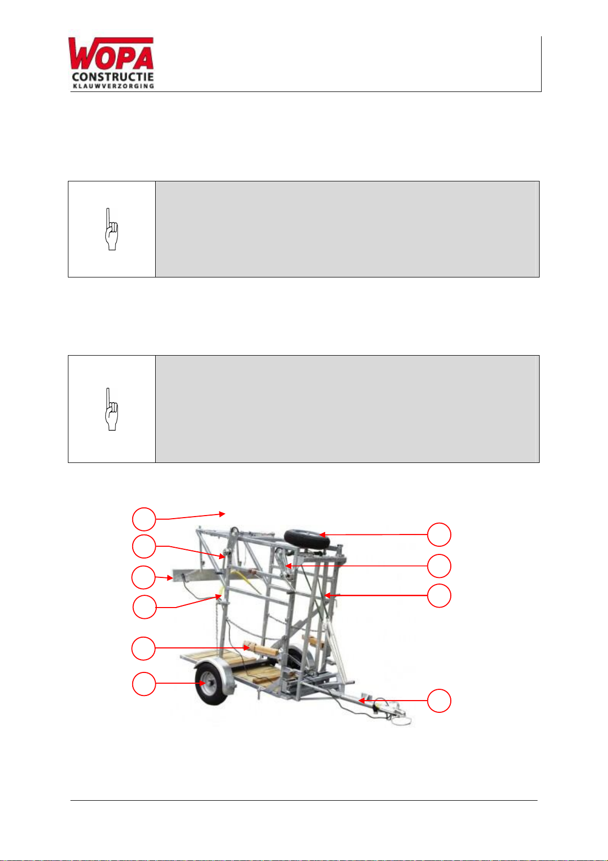
2.1. DESCRIPTION OF THE MAIN COMPONENTS SA0035 ................................................................10
2.2. ELECTRICAL INSTALLATION ..................................................................................................12
3. SAFETY..................................................................................................................................................14
3.1. GENERAL...........................................................................................................................14
3.2. DURING NORMAL USE..........................................................................................................15
3.3. OPERATING PERSONNEL......................................................................................................15
4. INSTALLATION......................................................................................................................................16
4.1. LOCATION..........................................................................................................................16
4.2. CONNECT THE MACHINE. .....................................................................................................18
4.3. PREPARING FOR TRANSPORTATION.......................................................................................18
5. OPERATION...........................................................................................................................................19
5.1. STARTING UP .....................................................................................................................19
5.2. EMERGENCY STOP..............................................................................................................19
5.3. PRODUCTION .....................................................................................................................20
5.4. HOOK UP THE FRONT LEG....................................................................................................21
6. MAINTENANCE......................................................................................................................................22
6.1. MAINTENANCE DIAGRAM......................................................................................................23
6.2. CLEAN THE MACHINE...........................................................................................................24
6.3. LUBRICATION OF REAR GATE................................................................................................24
6.4. CHECK PLAY IN THE WHEELS................................................................................................25
6.5. PARTS...............................................................................................................................26
7. DISPOSAL AS WASTE...........................................................................................................................27
8. APPENDIX..............................................................................................................................................28
8.1. LOGBOOK..........................................................................................................................28
LIJST MET AFBEELDINGEN
FIGURE 1: OVERVIEW SA0035.............................................................................................................10
FIGURE 2: OVERVIEW OF THE ELECTRICAL INSTALLATION (THE TYPE OF HOOF TRIMMING CRUSH IN THE PHOTO
MAY DIFFER FROM YOUR INSTALLATION)..........................................................................................12
FIGURE 3: DETAILS OF CONVERSION FROM TRANSPORT SET-UP TO WORKING SET-UP..................................16
FIGURE 4: DETAIL OF HOOKING UP FRONT LEG ........................................................................................21
FIGURE 5: LUBRICATION OF REAR GATE..................................................................................................24

User manual
Hoof trimmingcrush:SA0035
Version: 24-09-14
Page 6 of 29
EC conformity declaration (copy)
We, Wopa Constructiebedrijf BV
Rector Hulshofstraat 10
7135 JV Harreveld
The Netherlands
: +31-(0)544 372415
: +31-(0)544 372445
Email: info@wopa.com
Website: www.wopa.com
declare, entirely under our own responsibility, that the product:
machine : Hoof trimmingcrush
type: SA0035
to which this declaration pertains, is consistent with the stipulations in Directives:
2006/42/EC (Machine Directive)
2004/108/EC (EMC Directive)
the following standards were taken into account:
NEN-EN-ISO 12100 Safety of machinery. Basic definitions, general design principles.
NEN-EN 349 Safety of machinery – Minimum gaps to avoid crushing of parts of the human body.
NEN-EN ISO 13849-1 Safety of machinery – Parts of the control systems with a safety function – Section 1:
General design principles
NEN-EN 60204-1 Safety of machinery – Electrical equipment of machines
Section 1: General requirements
The undersigned is authorised to compile the Technical Dossier:
The Netherlands - Harreveld, Settember 2014 J.W.A. Wopereis
Managing Director

User manual
Hoof trimmingcrush:SA0035
Version: 24-09-14
Page 7 of 29
Overview of symbols
The following symbols are used for all actions that jeopardise the safety of the user and/or technician
and require caution.
Attention!
Hazard:
High voltage!
Hazard:
High temperature!
Tip:
Offers quick insight or tips to carry out certain actions more easily and simply.

User manual
Hoof trimmingcrush:SA0035
Version: 24-09-14
Page 8 of 29
Pictograms
A number of pictograms and alerts are affixed to the installation to indicate possible risks to users,
among other things.
Pictogram
Description
Location
Type plate
On the machine frame
Read the user manual
Wear safety goggles when operating
machine
Wear hearing protection when
operating machine.
On the machine frame
Warning pictograms for mechanical
and electrical hazards
On the machine frame
Crushing hazard
By the rear gate, if present.
ATTENTION!
Check regularly whether the pictograms and signs are still clearly
recognisable and legible. Replace if this is no longer the case.

User manual
Hoof trimmingcrush:SA0035
Version: 24-09-14
Page 9 of 29
1. Technical information
SA0035
General
Ambient temperature during
operation - 10 to 40 ˚C
Noise production < 75 dB(A)
Machine dimensions
Length 2000 mm
Width 1850
mm
Height 2000
mm
Weight 325
kg
Maximum product dimensions
Length 3600
mm
Width 1850
mm
Height 2320
mm
Weight 750
kg
Electrical connection (optional)
Power supply 1 phase / AC -
National voltage 230 V
Fuse required 4.9 A
Connected load 0.75 kVA
Electrical connection (Compacta
optional)
Power supply 1 phase / AC -
National voltage 230 V
Fuse required 5.5 A
Connected load 0.66 kVA
Data for road
transport
Axial load 750 kg
Maximum drawbar load 100 kg
Coupling ISO 55mm -
Connection plug 7 or 13
pole
* see electrical diagram

User manual
Hoof trimmingcrush:SA0035
Version: 24-09-14
Page 10 of 29
3
5
2
8
7
4
1
9
6
10
2. Description of the installation
FUNCTION
This section gives an overview of the most important components and
functions. If detailed information is available elsewhere in the manual, you are
referred to the specific sections.
The design of your crush may differ from the figures below.
2.1. Description of the main components SA0035
FUNCTION
The SA0035 was developed especially for dairy cattle hoof trimming in the
barn.
The SA0035 is equipped with an axle with a draw bar and is suitable for
transport on public roads.
The main components of the crush are shown in the illustration below:
Figure 1: Overview SA0035

User manual
Hoof trimmingcrush:SA0035
Version: 24-09-14
Page 11 of 29
Main components SA0035:
Figure 1
Component
Description
See
Section
1 Front gate operating
rope
Pulling on the rope closes the front gate.
If one wants to open it, the front gate can be
unlocked by pulling the rope upward and back
at an angle and then opened by slackening the
rope.
2 Manual hind leg winch
After the strap is attached round the hind leg as
shown in the photo above, the leg can be
hoisted using the manual hoist so the hoof can
be treated.
As an option, this operation can be done with
an electric motor.
3 Transport set (light bar)
A light bar with a license plate is attached to the
crush for transport on public roads.
4 Rump chain
Rear gate (option)
After the cow is moved into the crush, the rump
chain is stretched tightly behind the animal and
secured.
The rear gate is an option. This must be
pressed tightly against the cow and secured to
the side with a chain (if the chain is too loose,
the cow can sit on its haunches).
5 Front leg support
The cow’s front leg can be secured to the front
leg support with a rope so the leg can be
treated.
Optionally, the crush can be equipped with a
front leg support with a winch.
Another option is to equip it with a front leg
support with electric winch.
5.4
6+7 Transport set (axle)
An axle with mudguards and a spare tyre are
attached to the crush for transport on public
roads.
8 Manual belly strap
winch
Once the cowis moved into the crush, the belly
strap is attached behind the front legs. The belly
strap can be lifted using the manual hoist.
As an option, this operation can be done with
an electric motor.
9 Front gate
The front gate can be set to 3 positions using
the operating rope:
Entirely open: the cow can exit the crush at the
front.
Partially open: the cow can move its head
through the front gate but not its shoulders.
Stationary position.
Closed: the front gate is closed behind the
animal’s head.
10 Transport set (draw bar
arm)
A draw bar arm is attached to the crush for
transport on public roads.

User manual
Hoof trimmingcrush:SA0035
Version: 24-09-14
Page 12 of 29
4
3
5
1
2
2.2. Electrical installation
FUNCTION
The electrical installation provides power to the electric winches and the sockets
(as an option).
See the electrical diagram in the switch box on the crush for the rest of the
structure and controls of the electrical installation included in the delivery.
The placement of the control components on your installation may differ from
the photo below.
ATTENTION!
Work on the electrical installation can only be carried out by a technical expert.
Figure 2: Overview of the electrical installation (the type of hoof trimming crush in the photo
may differ from your installation).

User manual
Hoof trimmingcrush:SA0035
Version: 24-09-14
Page 13 of 29
The installation consists of the following components
Figure 2
Component
Description
Section /
location
1 Power supply cable
with plug
To connect the machine to the power supply.
2 Emergency stop
The emergency stop switches off all operations.
3 Relay box
A relay box is installed for each drive. It contains the
control components of the relevant drive.
4 Control buttons
Each drive has 1 or 2 control panels to operate the
following functions, depending on the version and/or
the options available.
oFront legs up/down
oBelly strap up/down
oHind legs up/down
o
Front legs and hind legs up/down

User manual
Hoof trimmingcrush:SA0035
Version: 24-09-14
Page 14 of 29
3. Safety
3.1. General
The guarantee will lapse and no liability will be accepted in the event of damage
caused by repairs and/or modifications not authorised by the supplier.
In the event of faultsplease contact the supplier.
The working area around the installation must be safe. The owner of the
installation must take the necessary precautionary measures in order to operate
the installation safely.
Starting up the installation in an area with a risk of explosion is prohibited.
The installation has been so designed that production is safe under normal
ambient conditions.
The owner of the installation must ensure that the instructionsin this manual are
followed in practice.
The safety features provided must not be removed.
Correct operation and safety of the system can only be guaranteed where
maintenance is carried out correctly and in good time, as prescribed.
Where work is to be carried out on the installation it must be disconnected from
the power supply, the power supply must be locked off and the system must be
depressurised.
There is a risk of trapping when operating driven moving parts. It is the
operator's responsibility to ensure that the installation is only started up when
no parts of his own or other people's bodies are in the vicinity of the trapping
zone.
Only authorised persons appointed by the owner may carry out work on the
electrical installation.
Ensure by means of internal procedures and supervision that all applicable
power supplies have been switched off.
The installation must not be used during cleaning, inspection, repairs or
maintenance, and must be disconnected from the electrical supply by means of
the plug and/or the main switch.
Welding work must not be carried out on the installation unless the cable
connection to the electrical components has first been disconnected.
The power supply to the control cabinet must not be used for the connection of
machinery other than the hand tools provided for.

User manual
Hoof trimmingcrush:SA0035
Version: 24-09-14
Page 15 of 29
3.2. During normal use
Check before commencing operations that no work is being carried out on the
installation and that it is ready for use.
Unauthorised persons must not enter the operational area of the installation. It
is the operator's task to check this.
3.3. Operating personnel
Operating personnel must be aged 18 or above.
Only authorised persons may carry out work with or on the installation.
Only work for which proper training has been received must be carried out.
This applies both to maintenance activities and normal use.
The operating personnel must be familiar with all potential situations, so that
rapid and effective action can be taken in an emergency.
Where a member of operational staff observes defects or risks or is not in
agreement with the safety measures, this must be reported to the owner or the
manager.
Safety footwear is mandatory.
Suitable work clothing is mandatory.
All employees must observe the safety instructions to avoid presenting a risk to
themselves and others. Comply strictly with the operating instructions at all
times.

User manual
Hoof trimmingcrush:SA0035
Version: 24-09-14
Page 16 of 29
1
3
2
4
5
6
7
8
9
4. Installation
EXPLANATION
Consult the technical data and the circuit diagram provided for the correct
specifications.
4.1. Location
CAUTION
The machine must be transported and installed upright.
Place the machine on a level and stable substrate
Take account of the instructions in Section 3 when carrying out any activity.
Failure to follow these may lead to serious injury.
Figure 3: details of conversion from transport set-up to working set-up.
No.
What to do
Action
Outcome
1.
Tip the crush back.
Tip the crush so that the drawbar is
clear of the ground.
2.
Take tension off the
belly belt.
The belly belt (Figure 3:1) holds the
drawbar under tension during
transportation.
Loosen the belly belt.
This stabilises the
drawbar during
transportation.

User manual
Hoof trimmingcrush:SA0035
Version: 24-09-14
Page 17 of 29
3.
Remove the drawbar.
Remove the locking pins (2*) (Figure
3:2) and slide the drawbar frame out
of the recesses.
4.
Remove the lighting
board.
Remove the lighting board from the
crush.
5.
Fold the rear gate
away.
Raise the rear gate.
6.
Tip the crush
forwards.
Lift the rear of the crush so that it tips
forwards. Lift by the rear gate
for less force.
7.
Remove the
mudguards
Loosen the locking elements (Figure
3:3) and lift the mudguard out of the
adapter.
8.
Tip the axle.
Take the tension off the locking pin by
bringing the hand winch (Figure 3:4)
up to tension. Where no winch is
provided there will be no tension on
the lever.
Remove the locking pin (Figure 3:10).
Turn the winch until the weight is off
the wheels and there is no longer any
tension on the lever (Figure 3:5).
Where no winch is provided place
your right foot on the wheel and lower
the lever (Figure 3:5) by hand. Ensure
that nobody is standing in front of the
lever or behind the crush.
Remove the locking pin (Figure 3:6)
from the lever.
Place the lever (Figure 3:5) in the
storage position (Figure 3:7) and
secure with the locking pin.
Rotate the winch again until the cable
is under tension.
9.
Slide out the front
gate stops.
The stops (Figure 3:8) are slid in for
transportation.
Press in the locking balls (Figure 3:9).
Slide out the stops to allow maximal
travel of the front gate.

User manual
Hoof trimmingcrush:SA0035
Version: 24-09-14
Page 18 of 29
4.2. Connect the machine.
CAUTION
Check that the voltage specified on the machine plate matches the mains
supply.
The machine must always be connected to an earthed socket to avoid the
risk of fire or electric shocks (the earth connection is coded green/yellow).
The electrical installation including the sockets must be connected in
accordance with local regulations.
The power cable must always be free and nothing must be placed on top of
it.
Replace the power cable immediately if it is damaged.
4.3. Preparing for transportation.
CAUTION
Preparing for transportation is the reverse procedure to making ready for
use (see 4.1).
With crushes equipped with an axle and drawbar it is essential that all
locking mechanisms are correctly installed.

User manual
Hoof trimmingcrush:SA0035
Version: 24-09-14
Page 19 of 29
5. Operation
CAUTION
Take account of the instructions in Section 3 when carrying out any activity.
Failure to follow these instructions may lead to serious injury.
5.1. Starting up
No.
What to do
Action
Result
1.
Switch on the power.
Insert the plug in the socket.
2.
Reset the emergency
stop.
Pull out the emergency stop buttons. The control unit is
now ready for use.
5.2. Emergency stop.
CAUTION
The emergency stop button must always be pressed in in the event of an
emergency.
All motions will cease following operation of the emergency stop button.
In order to take the machine back into use after an emergency stop the
emergency stop button must first be reset.
Before resetting the emergency stop button it must be ensured that
restarting the moving parts of the machine will not lead to a hazardous
situation.
Reset the emergency stop
No.
What to do
Action
Result
1.
Reset the emergency
stop button.
Reset the emergency stop button by
pulling it out or rotating it (depending
on the type installed) so that it returns
to its original position.
The machine is now
ready for use.

User manual
Hoof trimmingcrush:SA0035
Version: 24-09-14
Page 20 of 29
5.3. Production
No.
What to do
Action
Result
1.
Check that the crush
is ready for use.
See Section 5.1.
2.
Place the front gate
ready.
Open the front gate so that the head
of the animal can pass through but
not its withers.
3.
Place the cow in the
crush.
Lead the cow into the crush until its
head has passed through the front
gate.
Close the front gate.
4.
Attach the rump chain
or rear gate.
Tighten the rump chain around the
animal and secure it.
(SA0018/SA0022)
Lower the rear gate and secure it with
the chain (SA0026).
In order to avoid the risk of damage
to the rear leg, ensure that the rear
gate is pressed up tightly against
the animal.
5.
Apply the belly belt
Place the belly belt under the belly
behind the front legs and tighten it.
Where the (optional) electrical drive to
the belly belt is present, the belt
remains connected and is raised from
the floor until it comes up under the
belly.
6.
Process a rear hoof.
Place the belt around the rear leg and
raise the leg.
Process the rear hoof.
Allow the leg to drop and release it.
Table of contents
Other Wopa Farm Equipment manuals