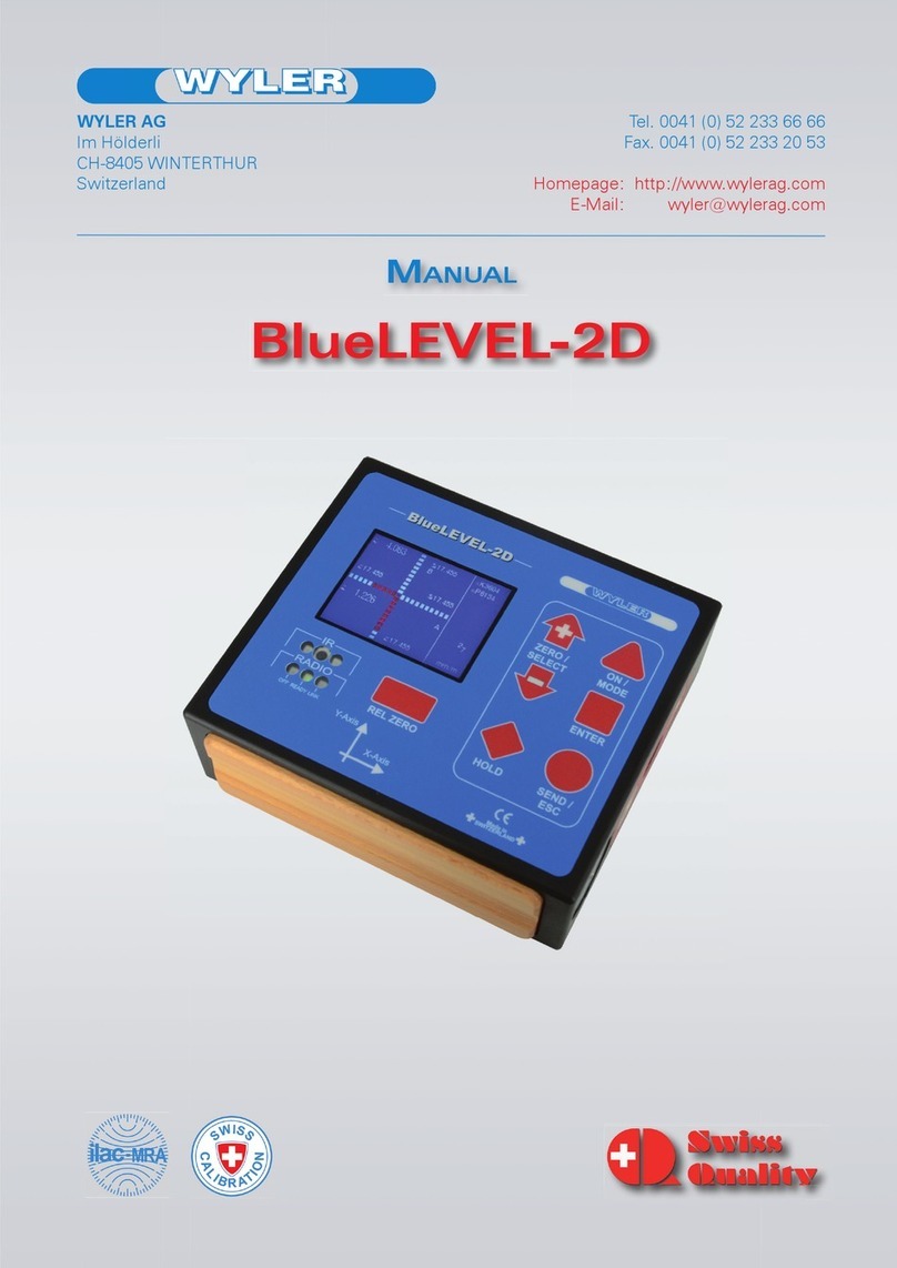
WYLER BlueSYSTEM User manual


Seite 3 von 100
CONTENT
Subject
Page
1
BASICS /INTRODUCTION
6
2
PREPARATION AND STARTUPOF THE MEASURING INSTRUMENTS
7
2.1
BATTERIES
7
2.1.1
INSERTING RESPECTIVELY REPLACEMENT OF BATTERIES IN BLUELEVEL
7
2.1.2
INSERTING RESPECTIVELY REPLACEMENT OF BATTERIES IN BLUEMETER
7
2.1.3
INSERTING RESPECTIVELY REPLACEMENT OF BATTERIES IN BLUETC
7
2.2
INITIAL STARTUP OF THE INSTRUMENTS
8
2.3
CONNECTING THE INSTRUMENTS
9
2.3.1
CONNECTING THE BLUEMETER
9
2.3.2
CONNECTING THE BLUETC
9
2.4
COMBINE A GROUP OF INSTRUMENTS TO A MEASUREMENT GROUP USING THE FUNCTION „JOIN“ IN
RADIO TRANSMISSION MODE
10
2.4.1
PROCEDURE FUNCTION „JOIN“
10
2.4.2
PROCEDURE"JOIN" WITH WIRELESS DATA TRANSMISSION
11
2.4.3
SPECIAL CASES “JOIN”
12
2.5
UNHINGE AN INSTRUMENT IN THE RADIO MODEFROM A GROUP BY USING THE FUNCTION „LEAVE“
12
PROCEDURE„LEAVE“
11
2.6
RENEWED CONNECTION OF A MEASURING GROUP
12
3
DESCRIPTION OF THE KEYS AND FUNCTION OF THEBLUELEVEL
WITH AND WITHOUT RADIO TRANSMISSION
13
3.1
THE BLUELEVEL
13
3.2
VIEW OF FUNCTIONAL KEYS BLUELEVEL
14
3.2.1
REAR VIEW
14
3.2.2
TOPVIEW
14
3.3
FUNCTIONAL MENU WITH BLUELEVEL USING THE FUNCTION KEY
15
ADDITIONAL FUNCTIONS
20
3.4
TEACH-INOF THE IR-TRIGGER (ZAPPER)
20
3.5
OPERATING THE BLUELEVEL
21
3.5.1
DESCRIPTION OF THE VARIOUS KEYS
21
3.5.2
DESCRIPTION OF VARIOUS DISPLAY FORMS ON THE BLUELEVEL
25
4
DESCRIPTION OF THE BLUEMETER WITH OR WITHOUT RADIO MODULE
28
4.1
STARTING THE BLUEMETER
28
4.2
TYPICAL CONFIGURATIONS WITH BLUEMETER
29
4.3
OVERVIEW OF THE BLUEMETER:
30
4.4
FUNCTIONAL MENU WITH BLUEMETERUSING THE FUNCTION KEY
31
ADDITIONAL FUNCTIONS
40
4.5
TEACH-INOF THE IR-TRIGGER (ZAPPER)
41
4.6
OPERATING THE BLUEMETER
42
4.6.1
DESCRIPTION OF THE VARIOUS KEYS
42
4.6.2
DESCRIPTION OF VARIOUS DISPLAY FORMS ON THE BLUEMETER
45
5
BLUETC(TRANSCEIVER/CONVERTER)WITH OR WITHOUT RADIO MODULE
47
5.1
INITIAL STARTUP OF THE BLUETC
47
5.2
TYPICAL CONFIGURATIONS WITH BLUETC
48
5.3
OVERVIEW OF THE BLUETC
48
5.4
FUNCTIONAL MENU WITH BLUETC/STRUCTURE
49
5.5
OPERATING THE BLUETC
50
DESCRIPTION OF THE VARIOUS KEYS
50
APPENDIX
51
A
BASICS ANF GENERAL REMARKS ABOUT BLUESYSTEM AND INCLINATION MEASUREMENT
51
A1
INTRODUCTION TO THE BLUESYSTEM
51
A2
DIFFERENCE BETWEEN THE CONFIGURATION WITH BLUEMETERAND BLUETC
52
A3
INSTRUMENT’SOVERVIEW
53
THE INSTRUMENTS OF THE BLUESYSTEM -FAMILY IN DETAIL
53
A4
MEASURING PROCEDURE /GENERAL HANDLING
55
TYPICAL CONFIGURATIONS WITH /WITHOUT RADIO TRANSMISSION
55
A5
BASIC SETUP OF THE INCLINATION MEASURING INSTRUEMNTS /PLUS-MINUS RULE
57

Seite 4 von 100
A6
ABSOLUTE MEASUREMENT /RELATIVE MEASUREMENT /DIFFERENTIAL MEASUREMENT
58
A7
GENERAL REMARKS ABOUT “ANGLES”AND “INCLINATION”
60
A8
HEIGHT RELATED TO THE STEP LENGTH
61
A9
ZERO SETTING BYREVERSAL MEASUREMENT (ABSOLUTE ZERO)
62
B
APPLICATIONS
64
B1
MEASURING ABSOLUTE
64
B2
RELATIVE MEASUREMENT
64
B3
DIFFERENTIAL RESPECTIVELY REFERENCE MEASUREMENT USING AN ENGINEER SET
64
B4
ANGULAR MEASUREMENTS
67
B5
LINES AND FLATNESS MEASUREMENT (MANUALPROCEDURE)
68
C
WYLERSOFTWARE LEVELSOFT PRO
69
D
SOFTWARE FOR THEDEFINITION OF MACHINE TOOL GEOMETRY MACHINE TOOL INSPECTION
SOFTWARE MT-SOFT
71
E
EXAMPLE USING THE HYPER TERMINALOF WINDOWS OR WINDOWS TERMINALPROGRAM
(EXAMPLE IS WIN XP)
72
F
TECHNICAL DATA BLUESYSTEM
74
F1
WYBUS COMPATIBLE INSTRUMENTS
74
F2
CONNECTION THROUGH A LONG CABLE OR THROUGH WIRELESS TRANSMISSION
74
G
SPECIAL FUNCTIONS
75
G1
RESET TO FACTORY PRE-SETTINGS
75
G2
FIRMWARE VERSION
75
G3
ACTIVATE THE FUNCTION KEY ON THE BLUETC
76
H
TECHNICAL DATA BLUESYSTEM
77
H1
TECHNICAL DATA OF THE RADIO MODULES
77
H2
TECHNICAL DATA OF THE BLUELEVEL
77
H3
TECHNICAL DATA OF THE BLUEMETER
78
H4
TECHNICAL DATA OF THE INTERFACE BLUETC
78
H5
PIN-DEFINITION FOR BLUELEVEL +BLUEMETER, BLUELEVEL +
BLUEMETERBASICAND BLUETC
78
I
SERVICE AND REPAIR
79
I1
REPAIR OF MEASURING INSTRUMENTS AND DISPLAY UNITS
79
I2
SERVICE-AND MAINTENANCE CONTRACTS
80
J
STORAGE OF THE INSTRUMENTS /CARE AND HANDLING OF THE BATTERIES
81
J1
STORAGE OF THE INSTRUMENTS
81
J2
CARE AND HANDLING OF THE BATTERIES
81
K
CONFORMITY DECLARATIONS ANDAPPROVALS
82
L
FLOWCHARTS
83
L1
POWER UP (BLUEMETERONLY)
83
L2
SAMPLING (BLUEMETERONLY)
84
L3
SENSOR(BLUEMETERONLY)
85
L4
REFRESH
86
L5
RELATIVE ZERO /REL.ZERO
87
L6
UNITS
88
L7
ZERO ABSOLUTE /ABS ZERO
89
L8
FILTERS
90
L9
RADIO (WIRELESS DATA TRANSMISSION)
91
L10
JOIN
92
L11
LEAVE
93
L12
HOLD
94
M
INDEX /KEYWORDS
95

Seite 5 von 100
MODIFICATIONS /ÄENDERUNGEN:
Date
Modified by
Descriptionof modifications
12.8.2005
HEH
“SEARCH” new defined
3.10.05
HEH/MO
New: Flowcharts
11.11.2005
HEH
Teach-In new; SENDnew; Key-Locknew
15.6.2006
HEH
Manual modified
29.1.2009
MG
WyBus-Integration
6.1.2015
HEH
New version: CONFORMITY DECLARATIONS ANDAPPROVALS
In the link list below, youwill findmore information on different important topics:
•Important ProductInformation
http://www.wylerag.com/en/support/certificates/
•Imagefilms, Instructionalvideosand Tutorials
https://www.youtube.com/user/wylerag
•Manualsund Compendium
http://www.wylerag.com/en/support/documentation/manuals/
•RepresentativesWYLER AG/ Product Training
http://www.wylerag.com/en/contact/representatives/
The following additional manualsmay be downloadedfrom http://www.wylerag.com:
DYNAM, the software for measuring and monitoring data deliveredbythe ZEROTRONIC-
sensors
LEVELSOFTPRO, the software for measuring flatnessand inclinationwith WYLERinclination
measuring instruments
MT-SOFT, that givesthe possibility to measure individualelementsof machine toolswith
standard inclinationmeasuring instruments. The measured resultscan be saved and at a later
stage used forcomparison and put togetherto receive a thoroughresult of the over all
accuracyofthe machine tool.
COMPENDIUM, the guideto ourproducts, technology and to a varietyof applications.
Descriptionof the interface RS485
If for any reason it isnot possible to download the respective datawe willgladlysupplyagainst a nominalcharge a CD
"ALL-IN-ONE" with all the manualsin differentlanguagesincluded

Seite 6 von 100
1. BASICS /INTRODUCTION
The newBlueSYSTEM isa continuousfurtherenhancementof the wellknown and wellestablished measuring
instrumentsMINILEVEL NT + LEVELTRONICNT with orwithoutwirelessdata transmission. A BlueSYSTEM normally
consists of one ortwo measuring instrumentsBlueLEVEL and a displayunit BlueMETER.Depending on theapplication
the BlueMETERcan also be connected to a PCwith evaluation software allowingthe onlineevaluation andpresentation
of the values.
The BlueSYSTEMisavailablewith orwithout radiotransmission. When usingthe system with cable connectionsit is
possible to upgrade to wirelesstransmission at a laterstage.
Asits predecessor thisnewest generationof high precision electronicinclination measuring instrumentsisspecifically
suitable forthe precisionmeasurementof smallest angles. Applicationsare therefore inparticularthe measurement of
flatnessof surface platesorthe measurement of the geometryof machine tools. The sensoritself, the heart of every
precision measuringinstrument, hasbeen furtherenhanced aswell, to allowprecise measurementseven undercritical
environmentalconditions.
The newmeasuring instrumentsof the BlueSYSTEMfamilycan be used asindividualinstrumentsaswell ascombined
in a set. Instead of using a BlueMETERit isalso possible to use a BlueTCasan interface to the PC/Laptop.The
functionsare all the same with theexception of the LCDdisplaywhich isonly available with theBlueMETER.
The BlueSYSTEMalso formspart of the WyBus. Therefore a wide varietyof other WYLERsensors can be integrated in
the BlueSYSTEM: Forinstancethe BlueMETERcan read themeasuring valuesof ZEROTRONICsensors or it can
serve as a command andadjustment toolforZEROMATICsensors.
A set of instruments, also called ENGINEERSET, normallyconsistsof one ortwo BlueLEVEL(s)and one BlueMETER,
forming the idealtoolformeasuring flatnessand machinesunderworkshop conditions. Furthermore the ENGINEER
SET can be used foranylevelling taskor analysisof rotations.

Seite 7 von 100
2 PREPARATIONAND START-UP OFTHE MEASURINGINSTRUMENTS BEFORE STARTING
2.1 BATTERIES
The batteriesare not installed inthe newinstrumentsthey are delivered separately. It isrecommended to remove the
batterieswhen transporting theinstruments.
2.1.1 INSERTING RESPECTIVELY REPLACEMENT OF BATTERIES IN BLUELEVEL
The statusof the battery powerisdisplayed e.g.27(2, 7 Volt)
The lowest voltageis1, 7 Volt.Afterthislimit hasbeen reached a batterysymbol blinking isdisplayed.
When the „ “symbol isblinking the batteriesshould be replaced.
2 pieces 1.5V, Size “C” ALKALINE
2.1.2 INSERTING RESPECTIVELY REPLACEMENT OF BATTERIES IN BLUEMETER
3 pieces 1.5V, Size “C” ALKALINE
2.1.3 INSERTING RESPECTIVELY REPLACEMENT OF BATTERIES IN BLUETC
2 pieces 1.5V, Size “C” ALKALINE

Seite 8 von 100
2.2 INITIAL STARTUP OF THE INSTRUMENTS
General remarks:
The instruments belonging to a measuring group as described below in Pt. 2.4 is already done at WYLER’s
when the instrumentsare delivered.
When a group of instrumentsare shut off e.g. aftera measurement is completed, the groupset-up remains
saved. When started again, thecommunicationis immediately ready, no additional set-upis required.
When a group of instrumentsisextendede.g. byjoining orreplacing an instrument, thisnewlyadded
instrument must be joined according Pt.2.4 „Combine a group....“
First time start-upof a measuring group (BlueLEVELand BlueMETER)withradio transmission (wireless
transmission of the data):
1. Remove the instrumentswith care from the transport and storage case and insert the batteries
2. Place the instrumentson a clean horizontallyalignedsurface and switch on the instruments
(BlueLEVELand BlueMETER). Keep the two keys<ON/MODE> and <ZERO/SELECT±> (BlueLEVEL),
respectively the key <ON/MODE> (BlueMETER)pressed until all 5 LED’s are on. When the keys are
released on the display is seen „SYSTEM TEST“.
If the keys <ON/MODE> and <ZERO/SELECT±> (BlueLEVEL), respectively the key <ON/MODE>
(BlueMETER)are pressedlonger than10 seconds when STARTING the instrumentall the LED’s
are beginning to blinkand the automaticshut-off system is deactivated. In thestandard mode the
instrument isautomatically shut off after60 minutes.
3. The instrumentsare nowcommunicatingand aftera fewsecondsthe measured valuesare displayed.
The batterypowershould be checked (see below)
4. The measuring taskmay nowbe started.
First time start-up of a measuring group (BlueLEVELand BlueMETER) withoutradio transmission (transmission of
the data bycables):
1. Remove the instrumentswith care from the transportand storage case and insert the batteries
2. Place the instrumentson a clean horizontallyalignedsurface and connectthe instrumentswith the
cablessupplied
3. Switch on the instruments. Keep the two keys <ON/MODE> and<ZERO/SELECT±> (BlueLEVEL),
respectively <ON/MODE> (BlueMETER)pressed until all 5 LED’s are on. When the keys are released
on the display is seen „SYSTEM TEST“.
If the keys <ON/MODE> and <ZERO/SELECT±> (BlueLEVEL), respectively <ON/MODE>
(BlueMETER)are pressedlonger than10 seconds when STARTING the instrument all the LED’s
are beginning to blinkand the automaticshut-off system is deactivated. In thestandard mode the
instrument isautomatically shut off after60 minutes.
4. The instrumentsare ready foruse and the measured valuesare displayed. Thebattery powershould be
checked (see below)
5. The measuring taskmay nowbe started.
Remarks concerning thebatterypower:
BlueLEVEL
BlueMETER
Display of the
actual battery
power
(Example: 2,6 V)
Display of the actual
batterypower
(Example: 3,6 V)
The lowest voltageis1,7 Volt.Afterthislimithas
been reached a batterysymbolblinking is
displayed. The batteriesshould nowbe replaced in
due time.
The lowest voltageis2.8 Volt. After thislimit has been
reached a battery symbol blinking isdisplayed. The
batteriesshould now be replaced in due time.

Seite 9 von 100
2.3 CONNECTING THE INSTRUMENTS
2.3.1 CONNECTING THE BLUEMETER
CONNECTOR „A“
CABLE CONNECTION FOR INSTRUMENT BLUELEVEL OR WYBUS COMPATIBLE
INSTRUMENT
CABLE CONNECTION FOR EXTERNAL POWER SUPPLY
CONNECTION TO PCOR LAPTOP
CABLE CONNECTION FOR EXTERNAL POWER SUPPLY
CONNECTOR „B“
CABLE CONNECTION FOR INSTRUMENT BLUELEVEL OR WYBUS COMPATIBLE
INSTRUMENT
CABLE CONNECTION FOR EXTERNAL POWER SUPPLY
REMARKS:
AN EXTERNAL POWER SUPPLY UNIT MAY BE CONNECTED TO ANY FREE CONNECTOR
2.3.2 CONNECTING THE BLUETC
A1
A2
CONNECTION TO PCOR LAPTOP
CABLE CONNECTION FOR EXTERNAL POWER SUPPLY
B1
B2
CABLE CONNECTION FOR INSTRUMENT BLUELEVEL OR WYBUS COMPATIBLE
INSTRUMENT
CABLE CONNECTION FOR EXTERNAL POWER SUPPLY
REMARKS:
AN EXTERNAL POWER SUPPLY UNIT MAY BE CONNECTED TO ANY FREE CONNECTOR

Seite 10 von 100
2.4 COMBINE AGROUP OF INSTRUMENTS USING THE FUNCTION "JOIN"
The function "JOIN" enablesthe grouping of instruments. The
grouping preventsthe accidental reading of measuringvaluesfrom
instrumentsof anothermeasuring group. Thefunction "JOIN" canbe
performed using the cable connection orwith wirelessdata
transmission.
The function "JOIN" joinsall theinstrumentsconnected to a group.
Previously used groupingsare cancelled.
For the function"JOIN" in wirelessmode only one instrumentcan be added to the group at a time. No instrumentsmust
be connected by cablesat the same time.
2.4.1 PROCEDURE "JOIN" WITH CABLE-CONNECTION
1. Connect all instruments(BlueLEVEL andBlueMETER)
to be joined to a group withthe cablesprovided and
switch on all the instruments
2. Select on the BlueMETERthe menu "JOIN" using the
<ON/MODE> key. Confirm with the <ENTER> key. All
instrumentsconnected are nowsearched andjoined to
a group.
3. Afterestablishing thegroup a "REFRESH" willbe
performed.
4. Afterthe groupingthe command "SENSOR" willbe
performed. Asthe measuring mode isstill to be defined,
the message "not-defined" will be displayed
5. The measuring mode("A", "B" or"A-B" must now be
selected. Select themodepreferredusing the <ZERO/SELECT> keys(corresponding to the menu [SENSOR])
and confirm with <ENTER>
It is also possible to execute anyotherfunctionof the menu. Forinstance itispossible to integrate withfurther
"JOIN" commandsadditional instrumentswith wirelessconnection into thegroup
6. The sensors must be selected. Select thesensorsforA and -dependingon the measuringmode -also forB
using the <ZERO/SELECT> keys and confirm with <ENTER>. The measuring valuesare nowshown in the
display accordingto the selectedconfiguration.
7. Aftera successful grouping on both instrumentsthe green LED"READY" willblinkshortlyasmanytimesas
instrumentsare joinedin the measuringgroup(including the own address)
8. For using the wirelessmode (the wirelessmode must be switched-on on each instrument)the cablescan now
be removed. Afterremovingthe cablesthe measuring valueswillbe "freezed"fora short while and replacedby
emptyzeroesuntil, aftersuccessful connection, the measuringvalueswill be displayed again
Remark: Aftersuccessful connectionthe blueLED"LINK" willbe lighting on all theinstrumentsconnected.

Seite 11 von 100
2.4.2 PROCEDURE "JOIN" WITH WIRELESS DATATRANSMISSION
With the function"JOIN" an instrument canbe added bywirelessdata transmission to an existing group. Duringthis
procedure no instrumentmust be connected by cablesasotherwise the "JOIN" procedure forcableswill beperformed.
IMPORTANT:
Only two instruments can be grouped in one procedure. If more instrumentsare membersof a measuring group,
e.g. a BlueLEVEL "1", a BlueLEVEL"2" anda BlueMETERit is
recommended to groupfirst the BlueLEVEL "1"with the
BlueMETERandthen theBlueLEVEL"2" also with the
BlueMETER.The affiliation to the measuringgroup willbe
communicated between themembers.
The two instruments to be grouped must be set to the JOIN-
mode. The <ON/MODE> key must be pressed repeatedly until the
mode [JOIN] appearsin the display. Confirmwith <ENTER>
Searching
1. Both instrumentsare "searching" each other. During the
searching procedure the greenLEDon both instruments
are lit continuously. The instrumentsremainin the
"search" mode untiltheyhavedetectedeach other.
During the search process the followingpicture will bedisplayed:
Remark: The searching processmay go on forseveral minutesin bad communication conditions.
2. Group connection
Assoon asthe two instrumentshave successfullydetected each otherthe search processis stopped and thisis
visualised by a rapid blinking (4 to 5 times per second) of the green LED’s on both instruments.. The joining can
no be activated by
- using the <ENTER> key on one of the instruments
or
- the whole processmay be cancelledbypressing the <ON/MODE> key.
3. Afterestablishing thegroup a "REFRESH" willbe performed.
4. Afterthe groupingthe command "SENSOR" willbe performed. Asthe measuring modehasbeen cancelled
during the JOINprocedure thismode must be selectedagain.Themessage "not-defined" will be displayed
5. The measuring mode("A", "B" or"A-B" must now be selected. Select themodepreferred usingthe
<ZERO/SELECT> keys (corresponding to the menu[SENSOR])and confirm with <ENTER>
It is also possible to execute any otherfunctionof the menu. Forinstance itispossible to integrate withfurther
"JOIN" commandsadditional instrumentswith wirelessconnection into thegroup
6. The sensors must be selected. Select thesensorsforA and -dependingon the measuringmode -also forB using
the <ZERO/SELECT> keys and confirm with <ENTER>. The measuring valuesare nowshown in the display
according to the selectedconfiguration.
7. Aftera successful grouping on both instrumentsthe blue LED"LINK" will belitcontinuously. The green LED
"READY" will blinkshortly asmanytimesasinstrumentsare joined inthe measuringgroup (includingthe own
address)
Attention: If the LED"OFF" isblinking inred, a connection isnot possible (see chapter2.4.2/ special case)

Seite 12 von 100
2.4.3 SPECIAL CASES “JOIN”
In case both instrumentsare already joinedin different groupsof instrumentsthey do findeach otherbut they cannot
communicatetogether. The red LED “OFF” is blinking. The search process may be cancelled by using the key
<ON/MODE> or<ENTER>
If it is required to use one of the instruments in the new measurement group it is necessary to use the mode “LEAVE” to
cancel the existingconnection.
2.5 UNHINGE AN INSTRUMENT IN THE RADIO MODE FROMA GROUP BY USING THE FUNCTION „LEAVE“
Each instrument may be unhinged from anexistinggroupof connected instruments.
PROCEDURE „LEAVE“
1. If BlueLEVELinstrumentsare transmitting measuring
valuesto a BlueMETERora BlueTC,the keyson the
BlueLEVELsare locked. To unlocka BlueLEVEL, the
settingsat the BlueMETERhave to be changed insuch
a way it no longercommunicateswith thisBlueLEVEL.
2. The instrumentsto be disconnectedmust be set to the
mode LEAVE. The <ON/MODE> key must repeatedlybe pressed until inthe displayshowsthe mode [LEAVE].
Confirm with <ENTER>
3. During the leaving mode the blue LED is blinking under “LINK”, the green LED “READY” is not blinking
respectively off.
4. Afterthe successful procedure the green LEDisblinking onceforapprox. 1 second. With thisthe unhinge
process is finished.
2.6 RENEWED CONNECTION OF AMEASURING GROUP
Aftera measuring group hasbeen stopped e.g. afterthe termination of a measurement, the group of instruments
remainsintact. Afterthe restartthe communicationisautomatically activatedand the communication isstarted. The
process JOINmust not be repeated.

Seite 13 von 100
3 DESCRIPTIONOF THE KEYS ANDFUNCTIONOFTHE
BLUELEVEL WITH ANDWITHOUTRADIO TRANSMISSION
Starting the BlueLEVEL
Press the <ON/MODE> and<ZERO/SELECT±> keys located opposite on the
handle until all the LED‘s on top of the handle are illuminated and on the
display "SYSTEM CHECK" isshown before the actualdisplayappears.
3.1 THE BLUELEVEL
Large LCD display with actual measured value,
instrument’s address and measuring unit
(m/m or Arcsec)
LED showing activitiesof
radio transmission and
infrared contact.
Rotating handle
with LCDdisplay
Display of battery
power
When the"„"symbol
is blinking the batteries
should be replaced.
Attention: The housing isNOT rigidlyfixed to the
measuring base to avoid mechanical
tensions.
Functionalkeyson both
sides of the handle
column.
Antenna of radio
modulescovered and
protected
Sensorcell with
electronic modulesin
nitrogen filled, gastight
housing.
Measuring base
Attention: The housing isNOT rigidlyfixed to the measuring base
to avoid mechanicaltensions.

Seite 14 von 100
3.2 VIEW OF FUNCTIONAL KEYS BLUELEVEL
3.2.1 REAR VIEW
Functionsindicatorandinfrared
indicator
(see separate picture)
Buttonsforthe menu
Key
<ON / MODE>
Key<ENTER>
Key
<SEND/ ESC>
Buttonsforthe menu
Key
<ZERO / SELECT ±>
Key<HOLD>
Battery compartment
Connector
RS232 / RS422 / RS485
or
External powersupply
5V DC / max. 450 mW
3.2.2 TOP VIEW
IR-receiver (Infrared)
Instrument connectedvia radio
transmission (LEDblue)
Radio ON(LEDgreen)
The number of impulse is equal
to the numberof instruments
joined
Radio OFF(LEDred)
IR-receiver (LED red) illuminated
when receiving signal

Seite 15 von 100
3.3 FUNCTIONAL MENU WITH BLUELEVEL USING THE FUNCTION KEY
(same appliespartiallyforBlueMETERand BlueTC)/ according to G. Lasczyk
… using the key <ON/MODE>
FOR ADDITIONAL DETAILS PLEASE CONSULT THE FLOW CHARTS CHAPTER "L /FLOWCHARTS"PAGES 86.....97
Switching the
instruments
ON
-Starting the BlueLEVEL.Pressthe <ON/MODE> and <ZERO/SELECT±> keys located
opposite on the handle until all the LED‘s on top of the handle are illuminated and " SYSTEM
CHECK" is shown on the display. Afterstarting theactualmeasured value aswell asthe last
used unit isdisplayed.
-Starting the BlueMETER. Press the <ON/MODE> key until all the LED‘s are illuminated and
"SYSTEM CHECK" isshown on the display. Afterstarting the actualmeasured value aswell
as the last used unit and configurationisdisplayed.
SENSOR
(BlueMETER
only)
- Setting the active sensors/portsand selection of the single ore differentialmeasurement
display BlueMETERonly.

Seite 16 von 100
ABSOLUTE
Standard measuring mode, absolutemeasured value(Zero-offset considered)The instrument
displaysthe actual deviationfrom a horizontalplane.
REL ZERO
Relative measured value (In the relative mode a „ZERO-OFFSET“ determined e.g. by reversal
measurement is superimposed by the value „REL ZERO OFFSET“)
Option 1 / Automatic setup
Before After
Use the key <ON/MODE> select [REL.ZERO]and confirm with <ENTER>. First the following
picture isshown in the display
Using <ENTER> orthe IR-zapperforconfirmingthe choice.Theactualvaluesare collectedand
constantly displayed.
When the valueshave stabilizedthe relativeZERO can be confirmedwith <ENTER> orwith the
IR-zapper.
On the display the value “0.000” is seen. This is now the relative value considering the offset.
Thisvalue isused forall additionalmeasurementsasreference.
Cont.
Option 2 / Manual setup

Seite 17 von 100
REL ZERO
Use the key <ON/MODE> select [REL.ZERO]and confirm with <ENTER>. First the following
picture isshown in the display
Use <ON/MODE> forcancelling theprocedure
The following picture isseen. It showsan earliervalue fora ZERO OFFSET.
Thisvalue may nowbe changedmanuallywith thekey <ZERO/SELECT±> and then
confirmed with<ENTER>.
On the displaythe valueisseen. Thisisnowthe relative value considering theoffset. This
value isused for all additionalmeasurementsasreference. E.g.
UNIT
Selectionof unit ([mm/m] or[Arcsec])
Using the key <ON/MODE> select the menu [UNIT] and confirm with<ENTER>. Using the
keys <ZERO/SELECT ±> select the required unit and confirmwith <ENTER>.

Seite 18 von 100
ABS. ZERO
Setting of absolute ZERO with a reversal measurement.
Using the reversal measurement isa simple wayto determinethe exact ZERO OFFSETof the
instrument aswell asthe exact inclination of the surface the instrumentisplaced on.
- Slide the instrumentonto a flat, horizontally levelled surface (e.g. engineer'ssurface
plate).
- The positionof the instrument isto be marked on the surface.
- Use the key <ON/MODE> to get to the menupoint [ABS.ZERO] andconfirm with
<ENTER>
The following display isseen:
- Use the zapperorconfirm with <ENTER>. On the displaythe progressof the collected
valuesare visible in graphicform.
When the curve isgetting a straight lineconfirm thefirst value withthe zapperorwith
<ENTER>
- Afterthe first reading the followingdisplayisseen:
Thisdisplay meansthe first readingwassuccessful. The instrument must be turned
180 degreeswithout liftingit andslid exactly ontothe previously marked position
- Use the zapperorconfirm with <ENTER>. On the displaythe progressof the collected
valuesare again visible in graphicform.

Seite 19 von 100
Cont.
ABS.ZERO
- When the curve isgetting a straight lineconfirm again the second valuewith the zapper
or with <ENTER>
Afterthe second reading the followingdisplay isseen:
With thisthe reversal measurement isfinished and the instrument showsthe true absolute
value.
FILTER
Setting a filtertype
Using the key <ON/MODE> select the menu [FILTER] andconfirm with <ENTER>. With the
key <ZERO/SELECT ±> choose the filtertype and confirmwith <ENTER>.
RADIO
Switch radio modeONorOFF(using cable transmission)
Use the key <ON/MODE> select the menu[RADIO] and confirm with <ENTER>.
For definitelyswitchingOn orOff confirm again with <ENTER>. Afterswitching the radio OFF
the redLED on the handle is on.
Returning to the radiomode followthe same procedure. When theradiomodeison, the green
LED on the handle is on.
JOIN
Combine a group of instrumentsto a measurement group
See detailed description inchapter2.4:
Combine a group of instrumentsto a measurement group using thefunction"JOIN" In radio
transmission mode
LEAVE
Unhinge an instrument inthe radio mode froma group
See detailed description inchapter2.5
Unhinge an instrument inthe radio mode froma group by using the function "LEAVE"
FOR ADDITIONAL DETAILS PLEASE CONSULT THE
FLOW CHARTS CHAPTER "L /FLOWCHARTS"PAGES 86.....97

Seite 20 von 100
ADDITIONAL FUNCTIONS
Function KEY-LOCK / keylock andunlock by usingthe push buttons
Using the following function thekeys maybe locked orunlocked
KEY-LOCK <ON> Keep the key <ENTER> pressed fora minimumof 2 seconds
until in the display shows „LOCKED“
When the keys are locked the respective symbol isdisplayed as
shown below
The KEY-LOCK functionismeant to eliminate any unintended pressing
of a key and starting an unplannedaction, such ase.g. a <HOLD>
function.
It is howeverpossible to make all the required measurementswithout
restrictions.
KEY-LOCK <OFF> Keep the key <ESC> pressed fora minimumof 2 secondsuntilafter
a short display of the sign "LOCKED" in the display theabovementioned
symbol disappearsand "UNLOCKED" isshown.
3.4 TEACH-IN of the IR-trigger (Zapper)
In orderto eliminateinterference of the zappersignalswhen several measuringgroupsare active inthe triggering
range the IRtriggercan be assigned to a specific measuring groupby applying thefunction TEACH-IN
Procedure TEACH-IN:
The measuring ordisplayinstrument must be started.
Keep the key <ZERO/SELECT ±> on the measuring ordisplay instrument pressed
Point the trigger(IRZapper)in the directionof the measuring ordisplayinstrument
Press the actuator key on the IRZapperuntil bothred IRLEDsare lightingup.
Thisprocedure must be done on allthemeasuring anddisplayinstrumentsusing the same IRtriggering.When the
instrumentsare dispatched thisprocedure isalready factoryset standard.
Other manuals for BlueSYSTEM
1
This manual suits for next models
3
Table of contents
Other WYLER Measuring Instrument manuals

WYLER
WYLER Clinotronic S User manual

WYLER
WYLER Clinotronic S User manual

WYLER
WYLER ML NT 11 User manual

WYLER
WYLER CLINOMETER 80 User manual

WYLER
WYLER Clinotronic S User manual

WYLER
WYLER Levelmeter 2000 User manual

WYLER
WYLER BlueCLINO User manual

WYLER
WYLER LEVELTRONIC NT User manual

WYLER
WYLER Clinotronic PLUS User manual

WYLER
WYLER Clinotronic S User manual