WYLER LEVELTRONIC NT User manual

WYLER AG
Im Hölderli
CH-8405 WINTERTHUR
Switzerland
Tel. 0041 (0) 52 233 66 66
Fax. 0041 (0) 52 233 20 53
Homepage: http://www.wylerag.com
E-Mail:wyler@wylerag.com
OPERATOR'SMANUAL
LEVELTRONIC NT and MINILEVEL NT
with
Radio transmission
and
LEVELMETER 2000
File: „nt_funke.doc“ April 24/.2000

Seite 2 von 53 Seiten
Content
Subject Page
1. BASICS 3
1.1. Instrument's overview 3
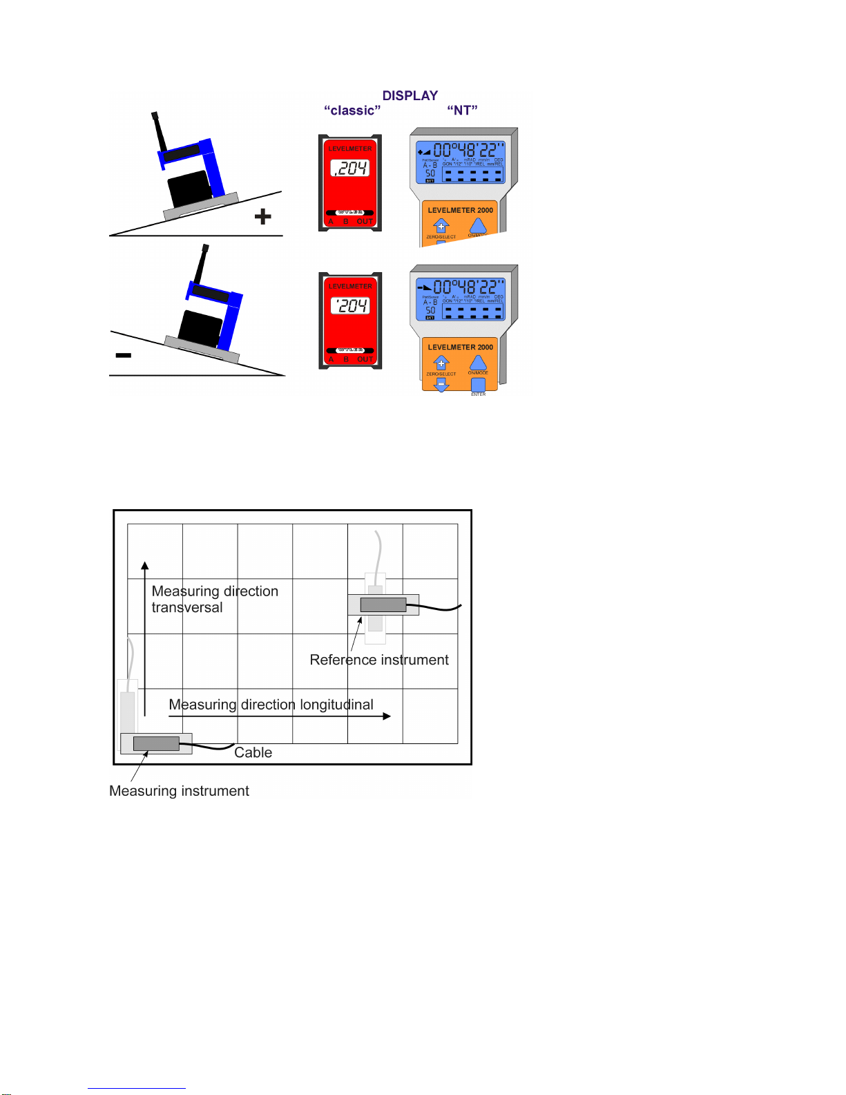
1.2. Measuring instruments / External display instruments 4
1.3. Measuring procedure / general use 6
1.4. Zero setting by reversal measurement (Absolute ZERO) 11
1.5. Applications 11
1.6. WYLER software LEVEL SOFT 16
2. DETAILED INFORMATION to the various instruments 18
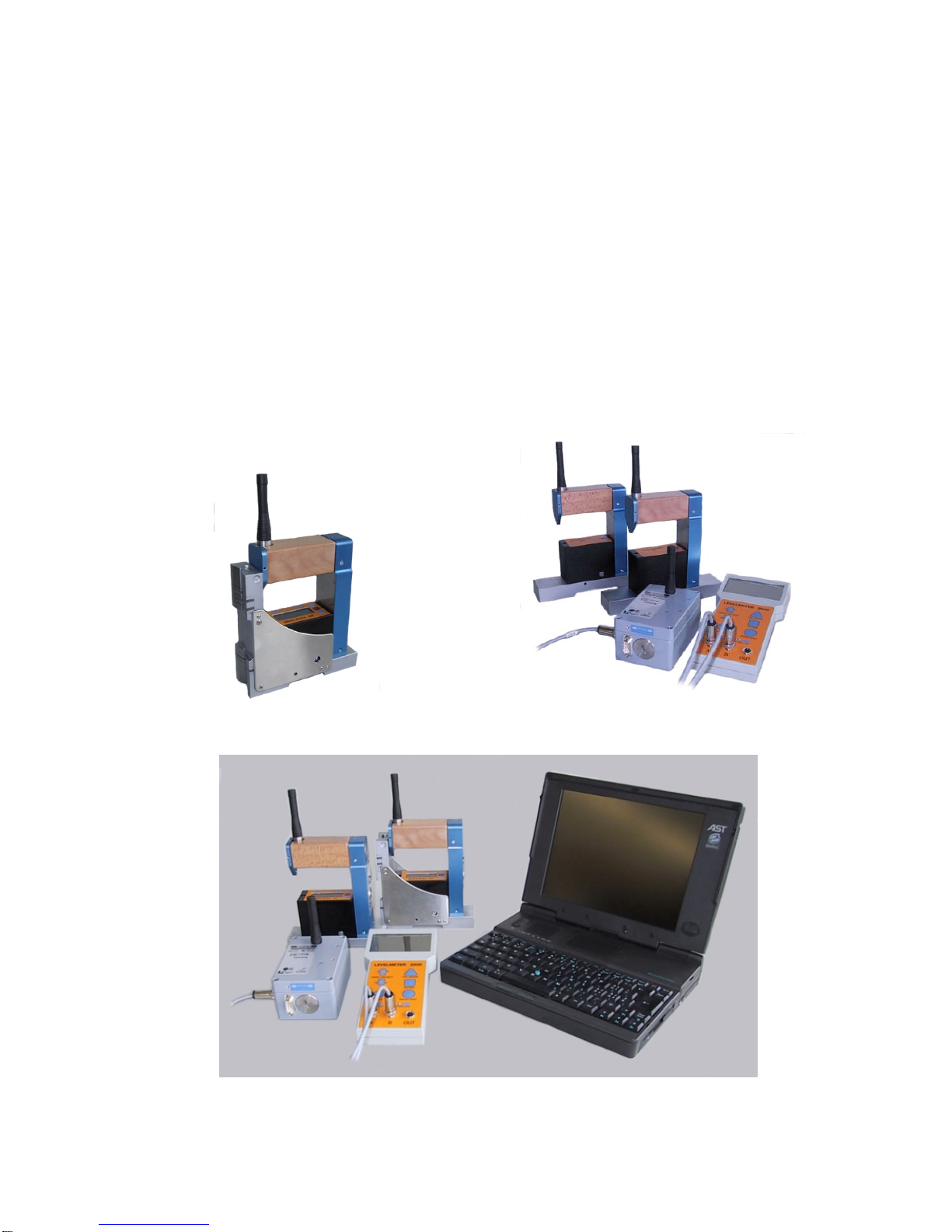
2.1. MINILEVEL / LEVELTRONIC „classic“ 18
2.2. MINILEVEL / LEVELTRONIC „NT“ 32
3. TECHNICAL DATA 45
3.1. LEVELTRONIC NT 45
3.2. MINILEVEL NT 45
3.3. RADIO MODULE 46
4. UPGRADE OF MINILEVEL NT AND LEVELTRONIC NT TO RADIO TRANSMISSION UNITS 47
5. MAINTENANCE / easy to cure malfunctions 49
6. ACCESSORIES / SPARE PARTS 51
7. STORING 51
8. DECLARATION OF CONFORMITY 52
Änderungen / Modifications:
Datum / Date Geändert durch
Modified by Beschreibung der Änderung
Description of modifications
The following manuals are ready for download on the internet homepage http://www.wylerag.com:
• DYNAM, the software for measuring and monitoring for use with ZEROTRONIC-
sensors
• LEVELSOFT WIN99, the software for inclination and flatness measurement with
WYLER inclination measuring instruments
• LEVELMETER 2000
• LEVELMETER „light“
• +CLINO PLUS+, the handy inclination measuring instrument
• CLINO 2000, the instrument with a number of features
• MINILEVEL / LEVELTRONIC „classic“ and „NT“
• Remote Display, the simple display unit
• COMPENDIUM, the informative brochure for our agents with an overview on our
products, technologies and applications
• Interface description RS485
These manuals can also be received against a nominal fee on a CD „ALL-IN-ONE“ if ordered at WYLER AG.
On this CD the manuals are available in different languages

Seite 3 von 53 Seiten
1. BASICS
The family of electronic inclination measuring instruments is very well suited for all kind of precision
measurement.
Two configurations are possible
I. Communication from the measuring instrument to the external display unit via cable
Using this conventional configuration the data transmission between the measuring instruments
(MINILEVEL NT und LEVELTRONIC NT) are connected to the external display unit (LEVELMETER 2000
or Levelmeter C25 (analogue model)) with cables
II. Communication from the measuring instrument to the external display unit via radio module
Using the configuration „wireless transmission“ the data will be transmitted via radio transmission to the
external display unit (possible with LEVELMETER 2000 only)
IMPORTANT: The MINILEVEL NT still can be used as stand alone instruments as well
Depending on the country in which the units are used the respective available free to use frequencies are
433MHz or 902 MHz.
(Technical data see Point 3)
1.1 INSTRUMENT’S OVERVIEW
MINILEVEL NT with integrated display and radio
transmission unit installed 2LEVELTRONIC NT with
LEVELMETER 2000 and cable connection
2MINILEVEL NT with LEVELMETER 2000 and
radio transmission module as an engineer set

Seite 4 von 53 Seiten
1.2 MEASURING INSTRUMENTS / EXTERNAL DISPLAY UNITS
Differences between MINILEVEL / LEVELTRONIC concerning display.
The MINILEVEL is equipped with an integrated
display and can be used as a stand-alone
instrument. It is however possible to connect it to
a Levelmeter (E.g. LEVELMETER 2000) to
receive remote display or to use it together with
another instrument for differential measurement.
Picture right:
MINILEVEL NT with integrated radio transmission
module
MINILEVEL NT with integrated radio transmission module
The LEVELTRONIC instruments are not
equipped with an internal display and require
therefore the connection to an external display
unit.
Picture rights:
LEVELTRONIC with integrated radio transmission
module
LEVELTRONIC NT with integrated radio transmission
module
2LEVELTRONIC NT with
LEVELMETER 2000
(Cable connection)
2LEVELTRONIC NT with
LEVELMETER 2000 and radio transmission box

Seite 5 von 53 Seiten
Differences between LEVELMETER 25, C25 and LEVELMETER 2000
LEVELMETER C25/DC
Measured values in analogue form possible via cables
only
The LEVELMETER C25 is very simple in using
Possible connections are:
• LEVELTRONIC NT
• MINILEVEL NT
• MINILEVEL „classic“
LEVELMETER 2000
Digital data transmission possible via cables or via
wireless transmission
The LEVELMETER 2000 has a number of built-in
sophisticated options, which can be used by the skilled user.
The Version „RADIO TRANSMISSION“ is only possible
with the LEVELMETER 2000
The LEVELMETER C25 and LEVELMETER 2000 are especially well suited for use with the above-mentioned
instruments, especially when differential measurement is applied in precision measurements. (Engineer set)
All the mentioned instruments are optimally used together with the flatness measurement software of
WYLER AG (LEVELSOFT WIN99)

Seite 6 von 53 Seiten
1.3 MEASURING PROCEDURE / GENERAL USE
1.3.1. TYPICAL CONFIGURATION WITH AND WITHOUT RADIO TRANSMISSION
Analogue data transmission
Two LEVELTRONIC NT or MINILEVEL NT are
connected to a LEVELMETER C25
Digital data transmission via cables
Two LEVELTRONIC NT or MINILEVEL NT connected
with a LEVELMETER 2000
Digital data transfer via radio transmission
Two LEVELTRONIC NT or MINILEVEL NT wireless
connected via a transmission box to a LEVELMETER
2000
Digital data transfer via radio transmission as well
as with cable
Generally it is also possible to connect one of the
instruments via cable to the LEVELMETER 2000 and
receive the data of the second, further away
instrument, via radio transmission to the
LEVELMETER 2000.
Additional information to the configuration can be seen under Point 2 „Detailed information to the various
instruments”

Seite 7 von 53 Seiten
1.3.2. BASIC SET-UP OF THE INCLINATION MEASURING INSTRUMENTS /PLUS -MINUS RULE
The instrument should always be placed in a way that the cable output is on the right hand side.
Inclined to the right: positive
Declined to the right: negative
(Practical remark: positive values
indicate that some material may be
removed on the measured piece)
Before starting the measurement enough acclimatization time must be allowed for the instruments.
Place the instrument (LEVELTRONIC or MINILEVEL) carefully to the required measuring spot. (Surface) and
read the value on the LEVELMETER or on the integrated display.
It is important to measure always in the direction of the cable connector, respectively the cable.
Example: Flatness measurement of a measuring and setting plate of granite
IMPORTANT:
• Touch the instruments only at the
handle (Temperature!!!)
• Measuring from left to right and from
closetofar.
• Cable respectively cable connector in
measuring
direction

Seite 8 von 53 Seiten
1.3.3 ABSOLUTE MEASUREMENT /RELATIVE MEASUREMENT /DIFFERENTIAL MEASUREMENT
Absolute measurement
(Absolute ZERO) Condition for the absolute measurement is the performing of a reversal measurement
for determining the absolute zero (to the center of the earth)
After this procedure the instrument will display the effective deviation from the center
of gravity. This means the value is an absolute angle of the measured surface.
Example: if the object to be measured is absolutely level, the display is "0"
Relative measurement
(Relative ZERO) A number of measurements do not require the absolute ZERO as described above.
Example: Angular deviation between two objects. (Lines, surfaces, guide ways)
The measurement instrument is placed on an object and the displayed value is
changed to "0". Then the instrument is relocated to a second object and the displayed
value of the angle is the angular difference between the two surfaces. If the display is
also "0", then both surfaces are parallel.
Most important is that always the instrument is placed on both positions in the same
direction.
Differential measurement
A differential measurement is a measurement with two instruments Measuring
instrument (A) and Reference instrument (B), measuring the angular difference
between the two. This means e.g. if the angular change in both instruments is the
same the displayed value (Difference A - B) does not change. In principle this is a
special relative measurement.
I the following measuring tasks the differential measurement is especially used
• Measurement on object with vibrations imposed.
• Measurements on unstable systems or objects
Example: Measuring the flatness of a machine bed. The reference instrument is
placed on a stable part of the machine where the measurement is not
interfered. With the measuring instrument the measurement is taking place
without removing the reference instrument.

Seite 9 von 53 Seiten
1.3.4 GENERAL REMARKS ABOUT "ANGLES"
Every angle may be defined in different
ways. The most popular way is a definition
in Degrees / Minutes / Seconds.
This is shown in the graph.
Such a definition is especially useful for
larger angles.
With an angular measuring instrument not only an
angle may be measured but also the height of a
certain point over a defined base length can be
calculated. for a profile of a line or a surface) Due to
this simple and reliable method a number of tasks
are possible, especially for measuring guide ways
and surface plates definition. Angle α
αα
α= Height of the measuring point related to a
defined base.
Height of the measuring point = tan α
αα
αx length of base
Example:
Angle = Height related to a defined base.
e.g.. 22 µm/m
Example:
Because the relation µm/m is 1/1'000'000 the same
relation can also be applied to micro inch/inch
Angle = Height related to a defined base.
e.g. 22 µm/m are equal to 22 micro inch/inch or
0,000022 Inch / Inch

Seite 10 von 53 Seiten
1.3.5 HEIGHT RELATED TO THE STEP LENGTH
Height Hx in [µm] related to
step length Height Hx [µm] = ]mm[LLength ]mm[LxSteplength]µm[HHeight ×
Height Hx in [micro Inch] related
to step length
1 micro Inch = 0,000001 Inch
Height Hx [micro Inch] = ]Inch[LLength ]Inch[LxSteplength]mikroINCH[HHeight ×
Height Hx in [µm] related to
step length Height Hx [µm] = ]mm[LxLength
3600
sec]arc[
tan ×
α
Height Hx in [micro Inch] related
to step length
1 micro Inch = 0,000001 Inch
Height Hx [micro Inch] = = 000'000'1]Inch[LxLength
3600
sec]arc[
tan ××
α

Seite 11 von 53 Seiten
1.4 ZERO SETTING BY REVERSAL MEASUREMENT (ABSOLUTE ZERO)
Using the reversal measurement is a simple way to determine the exact zero offset of the instrument as well as
the exact inclination of the surface the instrument is placed.
Reversal measurement for determination of:
I. Zero point deviation of the instrument
II. Inclination of the measured surface
Zero point deviation of the instrument Nm:
Inclination of the measured surface Np:
Procedure:
Prior to adjusting the zero point, the instrument should be allowed time to acquire the ambient, respectively the
work-piece temperature. Also the measuring system should have been switched on for about 1 min. (for
sensitivity of 1 mm/m about 3 minutes).
• Slide the instrument onto a flat, horizontally levelled surface (e.g. engineer's surface plate).
• The position of the MINILEVEL NT is to be marked on the surface.
• Set the display on the instrument or on the LEVELMETER to zero.
• The instrument must be turned 180 degrees and slid exactly onto the previously marked position.
• Read the value and divide by two
• Set the display on the instrument or on the LEVELMETER to the so calculated value
• Now reverse the instrument once more. The display should now show the same value as before but
with reversed indication.
1.5 APPLICATIONS
The following examples are displayed by using LEVELTRONIC NT and LEVELMETER. Naturally the same
measurements are possible by using MINILEVEL
1.5.1 MEASURING ABSOLUTE
Zero point is to be set by reversal measurement. Now the LEVELTRONIC/LEVELMETER will read deviations
from absolute horizontal position.
Using MINILEVEL NT and LEVELTRONIC NT with a LEVELMETER 2000 the value of the display is shown in
Arcsec or in µm/m.
Using one of the analogue instruments MINILEVEL „classic“ / „NT“ and LEVELTRONIC „classic“ / „NT“ with
connected LEVELMETER (25 or C25/DC) then the values displayed are "digits".
The digits must be multiplied by the value stated on the handle of the LEVELTRONIC and below the LCD on the
LEVELMETER to calculate the correct inclination.
The MINILEVEL „classic“ has two measuring ranges.
Range II is the fine range. The displayed digits must be calculated by multiplying with the correct sensitivity.
Range I is the coarse range. The displayed digits must be calculated by multiplying with the correct sensitivity
and the factor 10.

Seite 12 von 53 Seiten
1.5.2 MEASURING RELATIVE
It is not always required to set the instrument to zero by reversal measurement (absolute ZERO). If e.g. the
straightness of a line is measured only the relative most of the time the relative straightness is only required.
The same applies when lines, parallels, flatness is measured with the WYLER LEVEL SOFT. These are relative
measurements.
1.5.3 DIFFERENTIAL RESPECTIVELY REFERENCE MEASUREMENT USING AN ENGINEER SET
Such a measurement is useful or necessary if some of the following cases:
• Measurement on object with vibrations imposed.
• The inclination of the object to be measured will change by the weight of the instrument
• The floor is unstable (heavy loads in the close surroundings
• The relative pitch and roll on a machine must be measured.
The Engineer set usually consists of:
Two LEVELTRONIC NT or MINILEVEL NT with a
LEVELMETER C25
Picture:
Two LEVELTRONIC NT with a
LEVELMETER C25 (red cover)
Two LEVELTRONIC NT or MINILEVEL NT with a
LEVELMETER 2000
Picture:
Two LEVELTRONIC NT with a
LEVELMETER 2000 and a radio module
Remarks concerning NT instruments:
It makes sense to combine a LEVELTRONIC NT and a MINILEVEL NT to an engineer set. With such a
combination a great variety of other measuring tasks requiring a stand-alone instrument may be fulfilled.
Connecting the instruments performing a differential measurement
• One of the instruments is used a measuring instrument and the other as reference instrument.
• The measuring instrument is connected to port "A" the reference instrument to port "B".
• When analogue values are transmitted (LEVELMETER 25 or C25/DC) the sensitivity of the two
instruments must be identical.
• Both instruments must be placed looking the same direction.

Seite 13 von 53 Seiten
Examples for differential / reference measurement:
R= Reference instrument, connected to port „-B“
M= Measuring instrument, connected to port „A“
Fig.7
Rectangularity resp. parallelism of machine spindle in resp. to work table.
For precise square measurements an angular model fitted with magnets in the vertical face should be used.
(Elimination of deformation due to manual pressure).
Fig. 8
Straightness of table motion in relation to the machine’s base. The table must be moved step by step and the
measured value at each step should be noted/recorded after stabilization only.
Fig. 9
Inspection of perpendicularity and parallelism on large structures. Suitable instrument for outdoor applications.
Parallelism, Fig. 10
To conduct high precision measurements of parallelism (e.g. guide way rails two or more)
The reference LEVELTRONIC (R) will compensate for all changes in the objects orientation while
measurements are made. Using this method the instrument (sensitivities up to 1 µm/m) allows determination of
the exact shape of the guide ways.

Seite 14 von 53 Seiten
Torsion, Fig. 11
Torsion in guide ways and work piece surfaces. The instrument (M) is moved step by step in direction of X,
noting the reading at each step after allowing sufficient time for the instrument to settle. (Attention: Measuring
axis have to be parallel!)
This procedure is also applied when fastening work pieces in order to see possible tensions.
1.5.4 ANGULAR MEASUREMENTS
a) Small angles
The measuring instruments MINILEVEL and LEVELTRONIC are especially well suited for measuring small
angles. It is however to be considered that the larger the angle is getting the larger the linearity error of the
instrument is. It is therefore important to level the object to be measured (e.g. surface plate) as good as possible
in both axis.
b) 90°-angle (squareness)
For measuring 90° angles (square angles) instruments with an angular base can best be used. Before starting a
precision measurement the angular error of the instrument must be determined by reversal measurement on a
suitable object.
After the reversal measurement precision measurement with measuring uncertainty of 3 to 5 µm/m is
possible.
The determination of the instrument's angular error is done as follows:
In the WYLER LEVELSOFT 99 a new set-up allows the easy measurement of squareness of rectangular
objects.

Seite 15 von 53 Seiten
Principal procedure of a 90° measurement with WYLER LEVEL SOFT
The angular error of the instrument must be determined (optional)
The measurement follows the required set-up (Step length, number of measurements etc.)
After the measurement the respective lines may be adjusted according to different methods. For the following
three methods the angular errors are computed and displayed:
• Method Endpoints
• Method ISO1101
• Method Linear regression (least square)
Ask your local WYLER representative for further information of the software LEVEL SOFT
1.5.5 LINES AND FLATNESS MEASUREMENT (MANUAL PROCEDURE)
A principal procedure of a measurement of a line with WYLER instruments is described below:
Example:
• Sensitivity of the instrument 1 µm/m
• Length of measuring base 200 mm/ step length 180 mm
• The line to be measured must be divided in equal sizes according to the base available (calculated
step length) Overlapping of the steps is important, otherwise measuring errors are inevitable.
• Place the instrument at the begin of the line measurement
• Slide the instrument step by step along the line to be measured. Note all the measuring results after
allowing enough settling time. Then the line can be drawn as shown below considering the base
length and the sensitivity of the instrument.
This shows the
measurement of a line using
LEVELTRONIC „NT“ and a
LEVELMETER 2000
The data transfer is done via
radio module
Measurements on granite surface plates are done with instruments equipped with hardened steel bases with
dust groves. The sharp edges prohibit dust particles to get between the plate and the base when sliding the
instrument.
The manual measuring and the computing effort is quite big if possible at all and the source of errors large.
Such a task is best done with the WYLER LEVEL SOFT 99.

Seite 16 von 53 Seiten
1.6 WYLER SOFTWARE LEVELSOFT
The WYLER software LEVELSOFT well proven package based on the ISO 1101 for measuring lines and
surface flatness constantly upgraded to the demands of the user.
The following measurements can be done with the
WYLER LEVELSOFT in combination with the correct
measuring instruments:
• Lines (Straightness)
• Lines with twist (torsion)
• Parallelism
• Rectangularity
• Surface flatness
• Measurement on machine tools
•
Measurement of line according to ISO1101
with and without twist (torsion)
Measurement of parallel lines according
to ISO1101 with and without twist (torsion)
Surface flatness according to ISO 1101
as well as "U-Jack" method

Seite 17 von 53 Seiten
Rectangularity according to ISO1101
In order to connect the measuring instruments with a PC or Laptop an adapter is required
• LEVELADAPTER SET 2000 (for all type of instruments) or
• the special connecting set (LEVELSOFT no. 24A) to be used with instruments of the NT family together
with a LEVELMETER 2000

Seite 18 von 53 Seiten
2. DETAILED INFORMATION TO THE VARIOUS INSTRUMENTS
2.1 MINILEVEL NT WITH RADIO MODULE
MINILEVEL NT has an integrated display
and can be used as a stand alone instrument Two
measuring ranges can be set.
Two of the instruments can also be used for differential
measurements in combination with
• LEVELMETER C25/DC (red cover) / Art. no.
WYLER: 025-005 or
• LEVELMETER 2000 /Art. no. 065-004-001
(using cables or wireless transmission)
MINILEVEL NT
Blinking rapidly Blinking slowly Continuously
ON
LED red Sender/Receiver ON
Power for sensor ON Power for sensor
only ON Not enough
battery power
LED green Data transmission
(sending/receiving)
Connector Cable connection to LEVELMETER for conventional transmission
of data
ON / OFF Measuring instrument and data transmission ON/OFF
Display for 902MHz (USA)
see page 48
Channel
switch
6 Channels are available:
The same channel is required for the instruments connected
together
In case of transmission problems another channel may be chosen.
The originally used channel may be occupied by another user.
Switch ON the
instrument • press once only the button <ON/OFF> the instrument and the sender/receiver
starts to work. The red LED is blinking rapidly
• with another short push to the button the sender/receiver may be stopped. Local
measurement with the instrument only. The red LED is blinking slowly.
• with another short push to the button the sender/receiver is activated again
Switch OFF the
instrument • Press the button <ON>/<OFF> a few seconds until the red LED has stopped
blinking.

Seite 19 von 53 Seiten
MINILEVEL NT Functions
The MINILEVEL NT has three pushbuttons.
M = Mode
With this button the different functions may be chosen one after the other (see picture). For starting the
instrument this button "M" must be pressed.
• Press „M“ 1 x: Zero setting / „ZERO“ is flashing
• Press „M“ 2 x: Change measuring range I or II (The actual range is visible and flashing)
• Range I: Coarse range (Sensitivity x Factor 10)
• Range II: Fine range
Changes must be made with the buttons + / -.
Remarks:
Pressing the buttons +or -when ZERO mode is chosen will change the display by one unit. For larger changes
the button must remain pressed and the changes will gradually increase in speed.

Seite 20 von 53 Seiten
2.1.1 MINILEVEL NT COMBINED WITH THE LEVELMETER C25 (ANALOGUE DATA TRANSMISSION)
Analogue data transmission
One or two MINILEVEL NT connected with a
LEVELMETER C25
This configuration does not allow the use of wireless transmission because the LEVELMETER C25 is an
analogue display instrument
IMPORTANT: The measuring instruments must be switched ON via <ON/OFF> button the
red LED must be blinking rapidly. With another short push to the button the sender/receiver may be
stopped. Local measurement with the instrument only. The red LED is blinking slowly.
THE LEVELMETER C25
IMPORTANT: The display on the MINILEVEL NT is in µm/m or Arcsec.
The display on the LEVELMETER C25 is in digits only (sensitivity unit) in order to receive the
correct measured value the value must be multiplied by the sensitivity set on the MINILEVEL
(Range I or II)
Switch (Backside)
"On" / "Off" Switch for LEVELMETER. The low battery
indication (XX:XX colon) is appearing
automatically during operation if battery power is
insufficient.
Top view
LEVELMETER C25 / DC
Potentiometer:
"ZERO" (1) Enables adjustment of the zero point. The
regulating range is min. +/- 400 digits.
Socket A (2) Input for measuring with one
MINILEVEL „classic“
Socket -B (3) Input for the reference level in differential mode.
In order to prevent interference voltage to
channel A , input B is switched off when no
instrument is connected.
Socket:
"POWER/OUT (4) Analogue output 1 mV per digit.
External power supply input.
This manual suits for next models
2
Table of contents
Other WYLER Measuring Instrument manuals

WYLER
WYLER Clinotronic S User manual

WYLER
WYLER Clinotronic S User manual

WYLER
WYLER BlueCLINO User manual

WYLER
WYLER Clinotronic S User manual

WYLER
WYLER Levelmeter 2000 User manual

WYLER
WYLER BlueLEVEL-2D User manual

WYLER
WYLER CLINOMETER 80 User manual

WYLER
WYLER wylerLEVEL User manual

WYLER
WYLER CLINOMETER 80 User manual

WYLER
WYLER ML NT 11 User manual