manuals.online logo
Brands
  1. Home
  2. •
  3. Brands
  4. •
  5. Wyrestorm
  6. •
  7. Media Converter
  8. •
  9. Wyrestorm SW-0402-MV-HDMI User manual

Wyrestorm SW-0402-MV-HDMI User manual

4x12 Multi-View Scaler with 4K Output
SW-0402-MV-HDMI | SW-0402-MV-HDBT Quickstart Guide
In the Box
1x SW-0402-MV-HDMI or SW-0402-MV-HDBT Switcher
1x 12V DC 3A (SW-0402-MV-HDMI) Power Supply (US/UK/EU)
or 1x 12V DC 4A (SW-0402-MV-HDBT) Power Supply (US/UK/EU)
1x Handheld IR Remote
1x IR Receiver Extension Cable
2x Mounting Brackets
1x Quickstart Guide (this document)
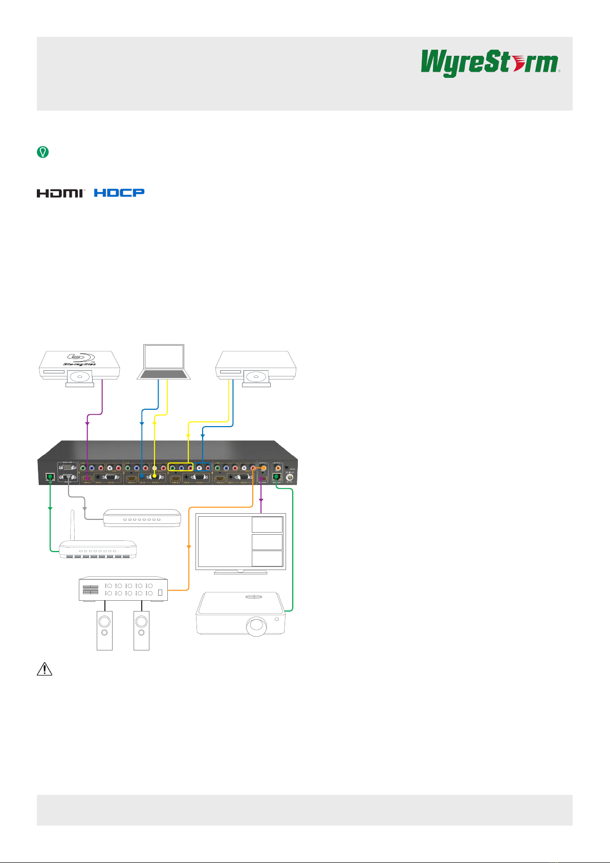
Basic Wiring Diagram
HDMI from Source
RS-232 to
Control System
LAN to
Router
HDMI to
Display
Analog Video
Analog
Video
Analog
Audio
Analog Audio
Digital Audio
HDMI Source YUV Source
VGA Source
HDMI Display
HDBaseT Projector
Satellite
Blu-ray
Camera
Laptop
IMPORTANT!
Do not connect or disconnect (hot plug) the HDMI or HDBaseT
connections while the transmitter or receiver is powered on. Doing so
may cause damage to the units or connected devices.
Additional Information
This Quickstart Guide provides the basic steps for the common uses of
this product. Refer to the Installation Guide and other documentation on
the product page for additional information
Installation
Before Beginning
WyreStorm recommends visiting the product page before installing this
product for updates to this Quickstart Guide as well as other information
about this product.
Verify that all items are included in the packaging per the In the Box list.
Pre Wire
1. Run a Cat5e/6/6a cable from the matrix location to the receiver
location. See Supported Video Resolutions for resolution distance
restrictions. Terminate the cable per the HDMI/HDBaseT Wiring
section.
2. (Optional) If using VGA with Audio, run the wire and terminate per
the Line In Wiring section.
3. (Optional) If using YUV (component video), run the wire and
terminate per the YUV/CVBS (Component/Composite Video) Wiring
section.
4. (Optional) If using Audio for a YUV input, run the wire and terminate
per the Audio In Wiring section.
5. (Optional) If using RS-232 to control the switcher, run the wire and
terminate per the RS-232 Wiring section.
6. (Optional) If using an external IR Receiver to control the switcher,
run the wire and terminate per the IR Wiring section.
Installation
7. Connect an HDMI source to an HDMI In on the switcher using an
HDMI cable from a high quality brand such as WyreStorm Express.
Repeat for other HDMI sources.
8. (Optional) Connect the VGA Out from a VGA source to a VGA In
on the switcher. Connect the audio out for the VGA source to the
shared Line In using the cable created in Pre Wire step 2. Repeat for
other VGA sources.
9. (Optional) Connect the Component Video Out from a Component
Video source to a YUV In on the switcher using the cable created
in Pre Wire step 3. Connect the audio out for the Component Video
source to the shared Audio In using the cable created in Pre Wire
step 4. Repeat for other VGA sources.
10. Connect an HDMI Out to an HDMI input on a display device. Repeat
using the other HDMI out for additional display devices.
11. Using the cable created in Pre Wire step 1, connect the 8-pin
RJ-45 female plug to the HDBT Out jack on the matrix. Repeat for
additional HDBaseT receivers.
12. (Optional) Connect the Digital Coax Output to a digital coax input
on the display device or amplier. Repeat for a second display
device if present.
13. (Optional) If using RS-232 to control the switcher, connect the DB9
connector to the RS-232 In port on the switcher and the opposite
end to a port on the control system using the cable created in Pre
Wire step 5.
14. Connect the LAN connection to a Local Area Network (LAN) router
or switch.
Copyright © 2015 WyreStorm Technologies | wyrestorm.com
SW-0402-MV-HDxx Quickstart Guide | 160330
North America: 518-289-1294 | EMEA/ROW: 44 (0) 1793 230 343
[email protected]
1 of 4
WyreStorm recommends reading through this document in its entirety to become familiar with the product’s features prior to starting the
installation process.
A dual-output multi-view scaler or 4x2 matrix, this device enables 4 sources to be shown on a single 1080p or in full resolution on a 4K display
Copyright © 2015 WyreStorm Technologies | wyrestorm.com
SW-0402-MV-HDxx Quickstart Guide | 160330
North America: 518-289-1294 | EMEA/ROW: 44 (0) 1793 230 343
[email protected]
2 of 4
Front Panel
Rear Panel
IR Sensor 38kHz IR Receiver.
Receives an IR signal from the included handheld remote or emitter for source selection and other switcher functions.
Input 1-4 Selection Selects the numbered input to assign to an output.
Source Selection Selects the source for the currently selected input number.
Example: HDMI 1, VGA 2, etc.
MV Mode Selects the MV mode for the currently selected source.
2K QV/4K QV Selected 2K or 4K output for the currently selected source.
LCD Display Displays current source selection and source type for each output.
LAN 8-pin RJ-45 female | 10/100 Mbps auto-negotiating
Connect to a Local Area Network for accessing the built-in Web UI.
RS-232 In/Loop
RS-232 Loop: 9-pin DB9 Male
RS-232 In: 9-pin DB9 Female
Connect to a control system to control the switcher and loop to other switchers. See RS-232 wiring section.
YUV/ CVBS
(Component/Composite
Video)
RCA Female(3x)
Connect YUV to the component video output of a source device.
Connect CVBS (YUV Green) to the composite video output of a source device.
Audio In
(CVBS Audio)
RCA Female (2x)
Connect to the analog audio output of the source connected to the CVBS input.
S/PDIF Out RCA Female (Digital Coax)
Outputs a digital S/PDIF audio signal to the display or amplier with a digital coax input..
IR Ext
3.5mm (1/8in) Stereo Plug
Connect to an IR receiver (not included) when the switcher is placed in a cabinet or out of range of the IR remote.
See IR Wiring.
HDMI In 19-pin type A HDMI female digital video/audio: Supports HDMI and DVI/D (requires adapter-not included).
Limited to 297MHz pixel clock
Line In (VGA Audio) 3.5mm (1/8in) Stereo Plug
Connect to the analog audio output of the source connected to the VGA input.
VGA In
15-pin VGA VESA (D-SUB 15):
Connect to D-SUB 15 VGA output of a device such as a computer.
15-pin VGA cable is required.
HDMI Out 19-pin type A HDMI female digital video/audio: Supports HDMI and DVI/D (requires adapter-not included).
Limited to 297MHz pixel clock.
HDBT Out 8-pin RJ-45 female
Connect to the HDBT In of an HDBaseT receiver. See HDMI/HDBaseT Wiring for important wiring guidelines.
Power In 5.5mm Male Barrel Jack
Connect to the included 12V DC 3A (SW-0402-MV-HDMI) or 12V DC 4A (SW-0402-MV-HDBT) Power Supply.
Copyright © 2015 WyreStorm Technologies | wyrestorm.com
SW-0402-MV-HDxx Quickstart Guide | 160330
North America: 518-289-1294 | EMEA/ROW: 44 (0) 1793 230 343
[email protected]
3 of 4
HDMI/HDBaseT Wiring
IMPORTANT! HDMI Wiring Guidelines
• The use of patch panels, wall plates, cable extenders, kinks in cables,
and electrical or environmental interference can have an adverse
effect on HDMI or HDBaseT transmission limiting performance. Steps
should be taken to minimize these factors (or remove completely)
during installation for best results.
• While similar in nature, the HDBaseT protocol is different than Ethernet
and voltages provided for PoH can be higher than those provided by
PoE. For this reason, never connect an HDBaseT link to an Ethernet
router or switch to avoid damaging the connected devices
Wiring for HDBaseT follows the EIA T568B standard.
Pin 1
Pin 8
Wire colors shown follow EIA/TIA-568B standard.
Pin 1:
Pin 2:
Pin 3:
Pin 4:
Pin 5:
Pin 6:
Pin 7:
Pin 8:
White/Orange
Orange
White/Green
Blue
White/Blue
Green
White/Brown
Brown
Supported Video Resolutions
Cable Type Range Supported Resolution
Cat5e
70m/230ft 1080p@60Hz 36bit
70m/230ft 1080p@60Hz 3D
Cat6/6a 35m/115ft 4K@60Hz 4:2:0 24bit
Local Area Network (LAN) Wiring
LAN wiring follows the EIA T568B standard
Pin 1
Pin 8
Wire colors shown follow EIA/TIA-568B standard.
Pin 1:
Pin 2:
Pin 3:
Pin 4:
Pin 5:
Pin 6:
Pin 7:
Pin 8:
White/Orange
Orange
White/Green
Blue
White/Blue
Green
White/Brown
Brown
Line In Wiring
Connection for Line In uses a 3.5mm (1/8in) stereo connector.
Tip:
Ring:
Left Channel
Right Channel
Sleeve: Ground (GND)
Audio In Wiring
Connection for Audio In uses an RCA Male connector for the left and the
right inputs.
Tip: Audio Postive (+)
Shield: Audio Negative (-)
YUV/CVBS (Component/Composite Video) Wiring
Connection for CVBS inputs use an RCA Male connector for each of the
individual connections.
Tip: Video Signal (+)
Shield: Video Ground (GND)
IR Wiring
Connection for IR RX (receive) uses a 3.5mm (1/8in) stereo jack that
outputs +5V DC to power the included IR receiver.
IMPORTANT IR TX Connection Guidelines!
• 3rd party IR receivers may require a different voltage, refer to the
documentation provided with the IR receiver before making any
connections to avoid damaging the device.
• When connecting to an IR control system use the WyreStorm CAB-IR-
LINK stereo to mono cable to remove the sleeve +5V DC.
Tip:
Ring: IR Signal
+5V DC
Sleeve: Ground (GND)
RS-232 Wiring
RS-232 Connection Guidelines
The following wiring diagram shows the pinouts for the switcher. While
not shown, connect the TX (transmit) to RX (receive) pins at the control
system or PC side of the cable.
Most control systems and computers are DTE where pin 2 is RX, this can
vary from device to device. Refer to the documentation for the connected
device for pin functionally to ensure that the correct connections can be
made.
Pin 1:
Pin 2:
Pin 3:
Pin 4:
Pin 5:
Pin 6:
Pin 7:
Pin 8:
TX (Transmit)
RX (Receive)
-------
-------
GND (Ground)
Outside of DB9
female chassis port
shown.
-------
-------
-------
Pin 9: -------
5
9 8 7 6
43 2 1
Copyright © 2015 WyreStorm Technologies | wyrestorm.com
SW-0402-MV-HDxx Quickstart Guide | 160317
North America: 518-289-1294 | EMEA/ROW: 44 (0) 1793 230 343
[email protected]
Warranty Information
This product is covered by a 2 year limited parts and labor warranty. During this period there will be no charge for unit
repair, component replacement or complete product replacement in the event of malfunction. The decision to repair
or replace will be made by the manufacturer. This limited warranty only covers defects in materials or workmanship
and excludes normal wear and tear or cosmetic damage.
Visit the product page located at wyrestorm.com for additional information on this product including important
technical information not provided in this document and warranty terms & conditions.
4 of 4
Specications
Audio and Video
Inputs
4x HDMI (1x 19-pin type A)
4x YUV (3x RCA Female)
4x CVBS – YUV Green (1x RCA Female)
4x VGA (1x 15-pin VGA VESA-D-SUB 15)
4x Audio In –YUV/CVBS Audio
(2x RCA Female)
4x Line In – VGA Audio (1x 3.5mm
(1/8in) Stereo)
Outputs
1/2x HDMI (1x 19-pin type A)
1x HDBaseT (8-pin RJ-45 female)
(SW-0402-MV-HDBT only)
2x S/PDIF (Digital Audio) RCA Female
Audio Formats 2ch analog | 2ch LPCM
Video Resolution Input: Up to 1080p@60Hz 36bit
Output: 4K@60Hz 4:2:0 24bit
Maximum Pixel Clock 297 MHz
Communication and Control
HDMI
HDCP | EDID
DVI/D supported with adapter (not
included)
HDBaseT EDID
Ethernet 10/100 Mbps auto-negotiating
(No IP Switcher Control)
Front Panel Switcher control
IR Switcher control with IR Ext for
connection to an IR Receiver.
RS-232 Switcher control with loop for additional
switchers.
Power
Power Supply
Input: 100~240V AC 50/50Hz
Output: SW-0402-MV-HDMI: 12V DC 3A
SW-0402-HDBT-HDBT: 12V DC 4A
Environmental
Operating Temperature 32°F ~ 113°F (0°C ~ 45°C)
10% ~ 90%, non-condensing
Storage Temperature -4°F ~ 158°F (-20°C ~ +70°C)
10% ~ 90%, non-condensing
Dimensions and Weight
Height 42mm / 1.65in
Width 439mm / 17.3in
Depth 254mm / 10in
Weight 2.85 kg / 6.27 kg
Regulatory
Safety and Emission CE | FCC | RoHS
Troubleshooting
No or Poor Quality Picture (snow or noisy image)
• Verify that power is being supplied to the transmitter and receiving
device and that both devices are powered on.
Note:
When using PoH, to power a receiver, verify that the HDBaseT cable is
properly terminated per the HDMI/HDBaseT Wiring section.
• Verify that the transmitter, matrix/receiver, and display support the
output resolution of the source. See Supported Video Resolutions.
• If transmitting 3D or 4K, verify that the HDMI cables used are 3D and/
or 4K rated.
• Verify that the HDBaseT cable is properly terminated per the HDMI/
HDBaseT Wiring section.
• Verify that all source and HDBaseT connections are not loose and are
functioning properly.
No or Intermittent Device Control
• Verify that the handheld remote has a clear line of sight to the IR
Sensor on the front panel or the IR Receiver if being used.
• Verify that the IR cable(s) is properly terminated if using an external IR
Receiver. See IR Wiring.
• Verify that the IR emitter is located near the IR Sensor on the front
panel if using an external IR Control System.
• Verify that the RS-232 cable is properly terminated. See RS-232
Wiring.
Troubleshooting Tips:
• WyreStorm recommends using a cable tester or connecting the cable
to other devices to verify functionality.
• Use a flashlight to locate the IR receiver behind any tinted panels on
the device being control.

Other manuals for SW-0402-MV-HDMI

1

This manual suits for next models

1

Other Wyrestorm Media Converter manuals

Wyrestorm NetworkHD 400 series User manual

Wyrestorm

Wyrestorm NetworkHD 400 series User manual

Wyrestorm NetworkHD 200 series User manual

Wyrestorm

Wyrestorm NetworkHD 200 series User manual

Wyrestorm NetworkHD 100 series User manual

Wyrestorm

Wyrestorm NetworkHD 100 series User manual

Wyrestorm SP-0208-HDBT-H2 User manual

Wyrestorm

Wyrestorm SP-0208-HDBT-H2 User manual

Wyrestorm NetworkHD 200 Series NHD-220-RX User manual

Wyrestorm

Wyrestorm NetworkHD 200 Series NHD-220-RX User manual

Wyrestorm NHD-400-E-TX User manual

Wyrestorm

Wyrestorm NHD-400-E-TX User manual

Wyrestorm CON-H2-DD-EARC User manual

Wyrestorm

Wyrestorm CON-H2-DD-EARC User manual

Wyrestorm SP-0104-H2 User manual

Wyrestorm

Wyrestorm SP-0104-H2 User manual

Wyrestorm NetworkHD 200 series User manual

Wyrestorm

Wyrestorm NetworkHD 200 series User manual

Wyrestorm NHD-230-TX User manual

Wyrestorm

Wyrestorm NHD-230-TX User manual

Wyrestorm NetworkHD 300 Series User manual

Wyrestorm

Wyrestorm NetworkHD 300 Series User manual

Wyrestorm NetworkHD 100 series User manual

Wyrestorm

Wyrestorm NetworkHD 100 series User manual

Wyrestorm NHD-100-TX v1 User manual

Wyrestorm

Wyrestorm NHD-100-TX v1 User manual

Wyrestorm NetworkHD 400 series User manual

Wyrestorm

Wyrestorm NetworkHD 400 series User manual

Wyrestorm EXP-CON-DAC-D v2 User manual

Wyrestorm

Wyrestorm EXP-CON-DAC-D v2 User manual

Wyrestorm NetworkHD NHD-IP-TX User manual

Wyrestorm

Wyrestorm NetworkHD NHD-IP-TX User manual

Wyrestorm CONV0211 User manual

Wyrestorm

Wyrestorm CONV0211 User manual

Wyrestorm EXP-SP-0104-H2 User manual

Wyrestorm

Wyrestorm EXP-SP-0104-H2 User manual

Wyrestorm NHD-400-TX User manual

Wyrestorm

Wyrestorm NHD-400-TX User manual

Wyrestorm NHD-000-CTL User manual

Wyrestorm

Wyrestorm NHD-000-CTL User manual

Wyrestorm NetworkHD 200 series User manual

Wyrestorm

Wyrestorm NetworkHD 200 series User manual

Wyrestorm NetworkHD 600 series User manual

Wyrestorm

Wyrestorm NetworkHD 600 series User manual

Wyrestorm NetworkHD NHD-500-TX User manual

Wyrestorm

Wyrestorm NetworkHD NHD-500-TX User manual

Wyrestorm NetworkHD 200 series Use and care manual

Wyrestorm

Wyrestorm NetworkHD 200 series Use and care manual

Popular Media Converter manuals by other brands

Winyuan 2E1-2ETH user manual

Winyuan

Winyuan 2E1-2ETH user manual

Honeywell SiX Series installation guide

Honeywell

Honeywell SiX Series installation guide

Radio Shack 15-2572T owner's manual

Radio Shack

Radio Shack 15-2572T owner's manual

Wellav UMH252 user manual

Wellav

Wellav UMH252 user manual

ANTIFERENCE HDMISS04 user guide

ANTIFERENCE

ANTIFERENCE HDMISS04 user guide

Perle S-100-XXXXX installation guide

Perle

Perle S-100-XXXXX installation guide

HEIDENHAIN LIF 171R Mounting instructions

HEIDENHAIN

HEIDENHAIN LIF 171R Mounting instructions

VRN K08B operation instruction

VRN

VRN K08B operation instruction

CEL-MAR ADA-4040PC8 user manual

CEL-MAR

CEL-MAR ADA-4040PC8 user manual

Honeywell TWM 9000 Supplementary instructions

Honeywell

Honeywell TWM 9000 Supplementary instructions

Honeywell Home PROSiXC2W Quick installation guide

Honeywell Home

Honeywell Home PROSiXC2W Quick installation guide

Staubli PV-K/SPL-Y Installation and operation manual

Staubli

Staubli PV-K/SPL-Y Installation and operation manual

Z3 Technology Sitara Z3-AM572x-RPS User instructions

Z3 Technology

Z3 Technology Sitara Z3-AM572x-RPS User instructions

HY-LINE CDM-660 manual

HY-LINE

HY-LINE CDM-660 manual

ATEN VC486 user manual

ATEN

ATEN VC486 user manual

Invertek Optidrive P2 series user guide

Invertek

Invertek Optidrive P2 series user guide

Texas Instruments TLC5510 manual

Texas Instruments

Texas Instruments TLC5510 manual

Artistic Licence Rail-Demux user guide

Artistic Licence

Artistic Licence Rail-Demux user guide

manuals.online logo
manuals.online logoBrands
  • About & Mission
  • Contact us
  • Privacy Policy
  • Terms and Conditions

Copyright 2025 Manuals.Online. All Rights Reserved.