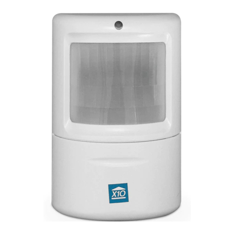
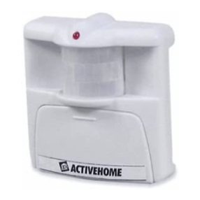
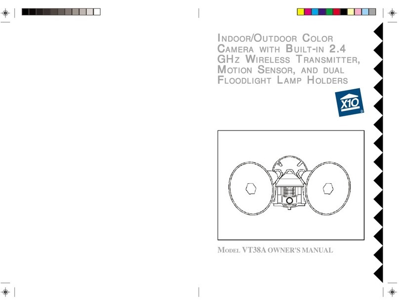
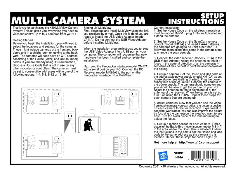
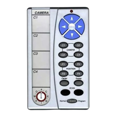
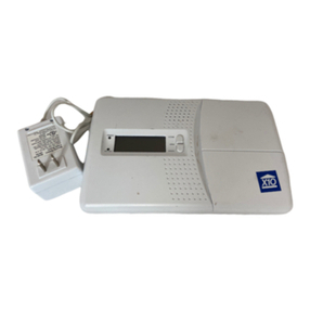
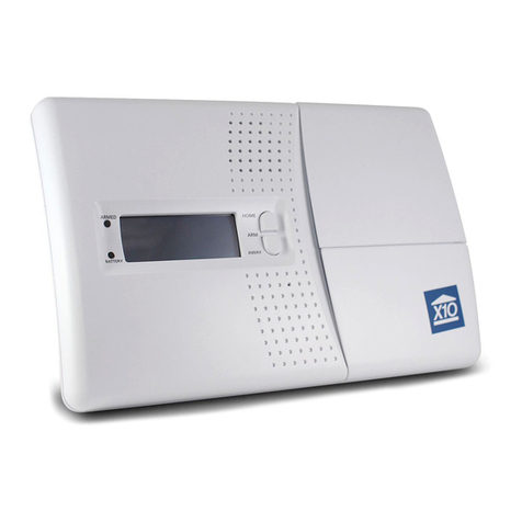
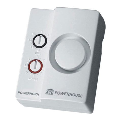
X10 Motion Monitor PR511 User manual

8s
.
w
POWERHOUSE
n
MOTION DETECTOR MODEL
PR511
OWNER’SMANUAL

INTRODUCTION
A QUICK
LOOK
AT YOUR MOTION DETECTOR
Your X-10 POWERHOUSE
TM
Motion
Detector gives your home a “lived-in”
look
when you are away, The built-in
infrared
sensor automatically turns on
your outdoor lighting whenever it de-
tects movement within its sensing
range.
Your Motion Detector
also
sends sig-
nals over your existing house wiring to
control other lights connected to X-10
Modules.
CONTENTS
A Quick Look
...................................
3
Covered Area...................................
4
Installing the Motion Detector
Choosing a Location
.....................
5
Preparing the Junction
Boxx..........
5
Assembling the Motion Detector
WiringDiagramm
............................
6
Installing the Motion Detector
.........
7
Adjusting the Motion Detector
........
8
Operation
Settings
............................
9
Controlling the
Motion Detector
10
Controlling Other Lights................
11
Code Selection Chart..................
1 I
This is X-10 POWERHOUSE..
......
12
Troubleshooting
. . . . . . . . . . . . . . . . . . . . . . . . . . . . .
14
Care and Maintenance
. . . . . . . . . . . . . . . . . . . .
15
Your Motion Detector can control up to
four sets of X-10 Modules when it
de-
tects
motion. and up to four additional
sets
of Modules for
dusk-to-dawn
oper-
ation.
Your Motion Detector features:
Sensor Head
-
automatically senses
motion over a wide area (110°).
X-10 Control
-
lets you
turn
on the
floodlights from any X-10 controller,
anywhere in your home.
Additional Light Control
-
turns on
up to four sets of lights when
motion
is
detected and can also turn on up to four
sets of tights at dusk and
turn
them off
at dawn.
Variable Timed Shut-off
-
lets you
set
the
length of time the lights stay on
after movement has stopped.
Photocell
Control
-
prevents
opera-
tion
during daylight hours and senses
when
to turn on and off lights for
dusk-
to-dawn operation.
Lamp Holders
Rated
for bulbs
up to
150W.
Mounting Plate
Fits over a
standard
round electrical box.
Sensor Head
Detects motion within
its-
sensing area (up to 40 feet
distance and
110°
angle
when mounted 6 feet off
the ground).
Control Panel Cover
Waterproof cover to pro-
tect control panel (see
page 8 for control panel
details).
D
1991 X-10 (USA) Inc.
a
All Rights Reserved.
is a registered trademark of X-10 (USA) Inc.
#@
POWERHOUSE is a trademark of X-10 (USA) Inc.

COVERED AREA INSTALLING THE MOTION DETECTOR
Position the Motion Detector so
that
a moving object cuts “across” its beams, not directly
towards them.
Motion
Path
Motion
Path
(Poor Detection)
(Good
Detection)
Motion
Path
(Good
Detection)
Sensor Position
(Good Location)
Nominal
Zonal
Coverage
(Plan
View)
a,
t
CHOOSING A LOCATION
You
must install your Motion Detector
on a standard, round outdoor electrical
junction
box.
Use either an
existing
box
overlooking
the area you want to
illumi-
nate or install a new box in the desired
location.
Consider the following when choosing a
location:
Your Motion Detector must be at
least 6 feet above the groundand be
parallel to the ground.
Existing floodlights must be aimed
away from the sensor.
Direct sunlight must not
fall
on
the
sensor lens.
l
The
sensor must not face reflective
surfaces such as swimming pools or
large windows.
l
You must not mount the sensor over
heat producing vents or
air-
conditioning units.
a
The sensor cannot “see” through
Note: The sensor “sees” a moving ob-
ject by detecting a change in tempera-
ture
as
an
object
moves. If you install
and set up your Motion Detector on a
very hot day it will be difficult for the
sensor to detect the difference between
the heat from your body and the back-
ground
temperature.
(At 98.6 degrees F.
you are invisible to the sensor.)
For best results. it is recommended that
you install your Motion Detector during
the day and make test adjustments dur-
ing the evening when it is cooler.
Cautious:
l
You must connect your Motion De-
tector
to
120 volts
AC. Check your
local
building
codes
before
installing.
l
If you do not have experience with
household wiring, have
a qualified
electrician install your Motion Detec-
tor.
l
Turn off
the
power at the main circuit
breaker or fuse panel before you be-
gin
installing.
Standard
Electrical
Wire
Color Code
Color
Black
White
Green or Bare Copper
Status
Hot (Live)
Neutral
Ground
PREPARING THE
JUNCTION BOX
You should mount
the
Motion Detector
and lamp holder assembly on a standard
round outdoor electrical junction box.
If the location you
selected
has a
rectan-
gular
junction box, replace it with the
round type, or use a rectangular
to
round adapter.
If the location you selected does not
have a junction box, complete all wiring
to the location before you mount the
Motion Detector.
Nominal
Zonal
coverage
(Side
View)

ASSEMBLING THE MOTION DETECTOR INSTALLING THE
MOTION
DETECTOR
1.Screw the base ofeachlamp holder
into
the
outer holes of the mounting
plate.
4. Lock the sensor head into place using
the locking ring.
You can install the Motion Detector in a
wall
box that is powered
all
the time or
in a wall box that is powered through a
wall switch.
If
the wall box is powered
from
a
wall
switch, leave the switch
turned
on all the time.
Turning off the
switch completely disables your Motion
Detector.
3.
Connect your Motion Detector’s
while wire to the house wiring’s
white wire, using a wire nut
2.
Rotate the locking ring on each lamp
holder towards the plate until the
lamp holder is secure against the
plate.
5. Locate each lamp holder’s white wire
and one
of
the
sensor head’s white
wires and connect all three wires to-
gether
using one of the supplied wire
nuts.
4. Connect your Motion Detector’s
black wire to the house wiring’s
black wire, using a wire nut.
3.
Screw
the threaded end
of the sensor
head into the center hole of the
mounting plate.
6. Locate each lamp holder’s black wire
and connect them to the sensor head’s
blue wire using
a wire nut.
Caution:
To
prevent
severe
damage to
your Motion Detector, do not connect it
to a dimmer or any kind of remote con-
trolled wall switch module.
Warning: Before making the following
connections, be sure the power
to
the
junction box is turned off. If the
junc-
tion box is powered a serious shock haz-
ard
exists.
1.
Install
the supplied gasket on the
junction box, and route the house
wiring through the gasket.
2. Connect the house wiring’s bare cop-
per ground wire to the junction box’s
ground
screw.
5.
Secure
the mounting plate to the
junction box using the two supplied
screws.
6.
Place
an
insulating
ring (supplied)
over
the
base
of each lamp and
screw
the lamps into their sockets.
Note: Lamp wattage should not exceed
150
watts
each when you use
the
sup-
plied
lamp
holders. Your Motion
Detec-
tor can power up to 500 watts if you use
it to
control
a
fixture
rated
at
500
watts.

ADJUSTING YOUR MOTION DETECTOR
OPERATION SETTINGS
This procedure
adjusts
the
aim of your
Motion Detector’s sensor head and
floodlights for best coverage.
For now.
simply set the controls as instructed. For
a
detailed description of each control’s
function refer to the next section.
Before you turn on the power:
1.
Open
the
control panel cover by
turn-
2.
3.
4.
5.
6.
7.
ing the metal locking screw.
Set the DUSK
control
fully clock-
wise to
LIGHT.
Set the RANGE control fullyclock-
wise to MAX.
Use a flat-bladed screwdriver to set
TIME DELAY control to 0.1.
Swivel the sensor head to point to-
ward the area you want to cover. Be
sure the sensor head remains level
from side to side and level with the
ground.
Caution:
Aim
the
sensor head below
the horizon. Direct sunlight can dam-
age the sensor. However. don’t point
the sensor head downwards. This re-
duces its range. For optimum opera-
tion, position the sensor head level
with
(parallel
to) the
ground.
Aim the floodlights at the area you
wish to light. If necessary, loosen the
screws to swivel the lamp holders.
Turn on the power and wait for 1
minute.
8.
Walk
around the covered area.
Whenever you move, the floodlights
come on and remain on until 6 sec-
onds after you stop moving. If neces-
sary, reorient the sensor head so that
normal road
traffic
does not activate
your Motion Detector. Tighten the
locking nut on the sensor head and
proceed to the next section to set all
controls for proper operation.
*
Index
Mark
YIN
LIGHT
RANGE
TIME DELAY
I.1
0
30
0.5
t
LI
16
MINUTES
SENSOR
IN
OUT
+l
I
+2
II
+3
LT
l
4
I
DUSK
THIS
UNIT
1
SENSOR
DUSK
DUSK
IN OUT
L
+5
I
+6
1
+’
I
+6
DUSK CONTROL
The
DUSK
control
adjusts the light lev-
el for turning on and off the Motion De-
tector in the dusk-to-dawn mode and for
turning on and off the sensor. For now,
set the DUSK
contro1
at
the
index mark
(*).
This is the correct setting for most
applications. You might need to adjust
this
contro1
for
better
dusk-to-dawn op-
eration. Turn the control toward DARK
if
the
Motion Detector
turns
on too ear-
ly.
Turn
the control toward LIGHT if
the Motion Detector turns on too late.
If you
set
the control
fully
clockwise (to
LIGHT), the sensor turns on the Motion
Detector when it detects motion all
the
time (even when it is not dark).
Note: When you change
the
setting of
this control, or when the light level
changes. the new setting
does
not take
effect
until
10 minutes
after
the
setting
was changed or the light level changed.
if movement is detected just after the
change was made, the new
setting
will
not take
effect
until
10 minutes after the
delay time you set on the Motion Detec-
tor.
If you change the setting and don’t want
to wait for
10
minutes, you can bypass
this delay by turning the power off
AF-
TER you change the
setting.
Then
turn
the
power back on and wait for 1 min-
ute.
RANGE CONTROL
The RANGE control adjusts the sensi-
tivity of the
sensor
head to movement.
Make
adjustments
in small increments
and test until you reach the desired sen-
sitivity.
If
pets or
other
small
animals
activate the Motion Detector,
turn
this
control towards MIN.
TIME DELAY CONTROL
The
TIME DELAY control sets the
length of time the lights stay on after
movement in the covered area has
stopped. You can
set
this time to 0.1
minutes (6 seconds), 0.5 minutes (30
seconds), 2 minutes, 5 minutes, 15 min-
utes
a 30
minutes.
THIS UNIT SWITCH
The THIS UNIT switch determines how
the floodlights function. If you
set
the
switch to SENSOR, the floodlights turn
on whenever there is movement in the
covered area. If you set the switch to
DUSK, the floodlights
turn
on at dusk
and off at
dawn.
Note: The setting of the THIS UNIT
switch does not affect how X-10 Mod-
ules operate. Their operation is deter-
mined by the settings of the individual
“DUSK” and “SENSOR” switches and
they can operate independently of the
floodlights. See “Controlling X-IO
Modules.”

CONTROLLING YOUR MOTION DETECTOR
You can use any X-10 Controller to turn
your Motion Detector on and off. Set
the HOUSE CODE and START CODE
dials, then follow your Controller’s in-
structions to control this light.
NOTE: If you turn
the
floodlights on us-
ing a Controller, they will stay on
until
you
turn
them off with a Controller.
They will not be affected by any move-
ment in the sensing area.
SETTING THE
HOUSECODE
Set the Housecode dial
to any of its 16
positions. If you have existing X-10
Modules, you should set it to the same
Housecode
you used for those Modules
so that the Motion
Detector
can
control
those modules.
SETTING THE
START CODE
The START CODE dial serves two pur-
poses. First, the number to which you
set this dial is the Unit Code for the Mo-
tion Detector (for controlling it from a
Controller). Also, the next eight num-
bers following on from the START
CODE will be the Unit Codes for the
modules your
Motion Detector controls.
(See controlling X-10 Modules.)
Caution:
If you plan to use the Motion
Detector to control additional
Modules,
keep in mind that these Modules might
turn on when you do not expect them to
(when a small animal passes within the
sensing
area, for example). For this rea-
son, take cafe if selecting appliances to
be controlled by the Motion Detector.
You might want a stereo to turn on
when
someone
approaches your house
(to make it sound like someone is
home), but you should make sure that
the Motion Detector cannot turn on
any-
thing which
would be dangerous if it
turned
on unexpectedly. An example of
this might be a coffee pot which could
be damaged and possibly
cause
a fire if
it turns on when
it is empty.
Do
not use the
Motion Detector to
control portable heaters. This could
cause a fire if the heater turns on unex-
pectedly when
clothing is nearby.
Choose your Unit Codes carefully.
CONTROLLING OTHER LIGHTS
Your Motion Detector can turn on up
to eight other lights or appliances con-
nected to X-10
Modules. Four of
the
Modules can be activated when there
is movement in
the
covered area.
The
other four Modules can be activated
with dusk-to-dawn operation.
1. Set the Module’s Housecode to the
same letter as the Motion Detector’s
Housecode.
2. For sensor operation, set the Mod-
ule’s Unit Code to the Motion De-
tector’s Start Code plus one, two,
three, or four. (For example, if your
Motion Detector’s Start
Code
is 4,
set the Module’s Unit
Code
to 5, 6,
7, or 8.)
3. For dusk-to-dawn
operation, set the
Module’s Unit Code to the Motion
Detector’s Start Code plus five, six,
seven, or eight. (For example, if
your Motion Detector’s Start Code
is 4, set the Module’s Unit Code to
9, 10, 11, or 12.)
4. For those Modules you are control-
ling with the Motion Detector. set
the corresponding SENSOR or
DUSK switches to IN.
5. Install the Modules according to
their instructions.
Be sure to
turn
off
the power at the
main circuit breaker panel or fuse
box before installing Wall Switch
Modules or Wall Receptacle Mod-
ules.
Note: When you first install an X-10
Appliance Module it might
already be
on. If you
don’t have an
X-10 Controller
to turn it off with, and you have set
the
Module
for
dusk-to-dawn
operation,
you
might have to wait
until
the next day for
the Module to
turn
off. See troubleshoot-
ing for an alternate method of turning
the Module off.
SENSOR switch
DUSK switch
S
Modules set to Modules set to
T
these numbers
turn
these
numbers
turn
on
at dusk and off
A
on when
motion
is
detected.
at dam.
R
T
Add the SENSOR
Add the DUSK
switch
number
to
switch
number
to
CStart Code number the Start Code
num-
O
to determine the
ber
to determine the
Module Unit Code.
DModule Unit Code.
E
START CODE
+
START
CODE
+
+l
+2
+3
+4
+5
+6
+7 +8
1
2345 6789
2
3456 78 9
10
3
4
5
6 7 8 9 10 11
4
5 6
7
8 9 10
11
12
5
6
7
8
9
10
11 12 13
6
7 8 9 10 11 12 13 14
7
8 9 10 11 12 13 14 15
8
9 10 11 12 13 14 15 16
9
10 11 12 13 14 15 16 1
10
11 12 13 14 15 16 1 2
11
12 13 14
15
16
1
2 3
12
13 14 15 16 1 2 3 4
13
14 15 16 1 2 3 4 5
14
15 16 1 2 3 4 5 6
15
16123 4567
16
1234
5678

This is
X-10 POWERHOUSE
Mini Timer
(MT522)
Instantly
controls up to eight X-10 mod-
ules and programs up to four modules to
turn on and off at specific times. Can
turn
lights on at random times for added
security. Dims lights too!
Home Automation Interface
(CP290)
Set up from an
IBM, Mac, Apple
IIe/IIc
or Commodore
64/128
computer and
then disconnected. It doesn’t tie the com-
puter up. Controls up to 256 Modules. 7
day timer can be set for 128
timed
events. Software included.
Maxi Controller
(SC503)
Controls up to 16
modules from any-
where in the house. Has
All Lights On
button and dims lights too!
Mini Controller
(MC460)
Compact unit allows you to
control
up to
eight modules from
anywhere in the
house. Has All Lights On button and
dims lights too!
SUNDOWNER
TM
(SD533)
Turns on up to 4 modules at dusk and
turns them off again at dawn. Also has
all the features of the Mini Controller.
Telephone Responder
(TR551)
Plugs into a regular phone jack and con-
trols up to 10 X-10 modules from any
touch-tone phone in the world. Can also
flash lights when the phone rings.
Lamp Module
(LM465)
Can be turned on and off and even
dimmed
from X-10 controllers. Rated for
300W.
Incandescent lamps only.
Appliance Module (AM486
-
2 pin)
(AM466
-
3 pin grounded)
For turning on an air conditioner, coffee
pot, TV, stereo, and so on. Rated at 15A
resistive (for coffee pots etc.),
1/3
HP
for
motors,
5OOW
for lamps.
Split Receptacle
Module (SR227)
Replaces your existing outlet and works
like an Appliance Module. Rated at 15
Amps unrestricted, Top outlet is con-
trolled, bottom one is a regular outlet.
Wall Switch Module
(WS467)
Replaces your existing wall switch and in-
stalls like a dimmer. Rated at 500W max.
60W min.
incandescent lamps
only.
3
-
Way Wall Switch
(WS4777)
For controlling a light which is presently
controlled by two switches. Rated at 500W
max. 60W min.
incandescent
lamps only.
Heavy
Duty Appliance
Modules
(HD243
-
220V,
15A)
(HD245
-
220V,
20A)
For
controlling
220V room air condition-
ers, water heaters etc. For single phase or
split phase
110/220V
wiring only (not suit-
able for 3 phase wiring).
Universal
Module
(UM506)
Momentary or sustained dry contact clo-
sure to control low voltage items such as
sprinkler systems etc. Also contains a
beeper to use as an annunciator. Works
with
all X-10 Controllers and Timers (ex-
cept BR52
1,
BC53 1 and ND65
1).

TROUBLESHOOTING
If the floodlights do not turn on.
Be sure that the Motion Detector has
power. Check that the wall switch (ii in-
stalled) is turned on.
Confirm the position of the THIS UNIT
switch.
Check
the setting of
the
DUSK control.
Note: If you change the DUSK control’s
setting you must wait 10 minutes for the
new setting to take effect.
If
a particular module controlled by
your Motion Detector does not turn
on or off.
Be sure
that the
Module has power and
the switch on the light or appliance is
ON.
Confirm that the Housecode on the Mo-
tion Detector and the Module are set the
same.
Check the setting of
the
Module’s Unit
Code.
Be
sure the SENSOR
or
DUSK switch
for that module is set to IN.
Try plugging the Module into another
outlet. If the Module does not work in
any outlet, replace the Module. If the
Module works in some outlets but not in
others, contact X-10 for help.
If your Motion Detector does not con-
trol any modules.
Be sure there is power
to
the Motion
Detector. If it is controlled by a wall
switch, check that the wall switch is
turned
on. Check that the Housecode is
set
correctly.
If you can’t get the Motion Detector
to turn off.
1.
Turn off power at the circuit breaker
panel. Wait 10 seconds.
2. Set the RANGE control
to
MAX.
3. Set the DUSK
control
to LIGHT.
4,
Set the
TIME
DELAY to 0.1 min-
utes.
5. Set THIS UNIT switch to SENSOR.
6. Turn power on at circuit breaker.
7. Wait
for 1 minute. Then walk past
the Motion Detector,
from side to
side. The floodlights will be on be-
cause they were on when you
turned
the
power off.
8. Ensure that the Motion Detector does
not detect any movement for at least
10 seconds. The floodlights
will
then
turn off.
9. Set the controls to your desired set-
tings.
POWER
INTERRUPTIONS
When the power comes back on after a
power failure, your Motion Detector
re-
turns
to the state it was in before the
power loss. Lamp and Wall Switch
Modules remain off after power is
re-
stored. Appliance Modules stay as they
were before the interruption.
INTERCOM SYSTEMS
Intercom
systems that send signals over
your house’s electrical wiring can inter-
fere with the operation of your X-10
Modules.
If the intercom system has its
own
separate
wiring it does not cause a
problem.
Note:
Modifying or tampering with your
Mo-
tion
Detector’s internal components can
cause a malfunction and might invali-
If a Module is on when you apply
pow-
er to the Motion Detector, the Module
will remain on until the Motion
Detec-
tor
turns it off. If you have set the
Mod-
ule
for dusk-to-dawn operation and you
don’t have a controller to tum it off
with, you might have to wait until the
next day for the Motion Detector to turn
the Module off. Or, you can temporarily
set the Module to be controlled by one
of
the
codes used when the Motion De-
tector detects motion. Then, walk past
the Motion Detector. The
Module
will
turn off after the delay time set on the
Motion Detector. You can then set the
Module back to the code used for
dusk-
to-dawn operation.
date its
warranty.

Important Notes
If the floodlights connected to your Motion Detector Light Control turn on
but do not turn off, follow these steps:
1.
Set RANGE control to MAX.
2. Set DUSK control to LIGHT.
3. Set TIME DELAY to 0.1.
4. Set THIS UNIT switch to SENSOR.
5.
Turn off the
power
at the circuit breaker
panel.
Wait 10 seconds.
6.
7.
8.
9
Turn the power back on at the circuit breaker (the floodlights will be on
at this time as they were on when you turned off the power).
Wait for 1 minute, then walk in front of the Motion Detector.
Ensure that the Motion Detector does not see any movement for 10 sec-
onds and check that the floodlights turn off.
Set RANGE, DUSK and TIME DELAY controls as desired, following
the instructions in the owner’s manual.
.
Your Motion Detector Light Control is now ready to use.
NOTE: When you first apply power to the Motion Detector, it will not start
working until after a delay of 1 minute.
Note also that the Motion Detector should NOT be
positioned
so that it
points above the horizon
-
damage to the photocell in the sensor head may
result if sunlight falls directly onto the photocell. The Motion Detector
should be parallel to the ground for optimum range. If you aim the Motion
Detector downwards you will reduce its sensing range.
Other manuals for Motion Monitor PR511
1
This manual suits for next models
1
Table of contents
Other X10 Security System manuals