XAL MOVE IT 1.1 User manual

Mounting for NODE starts on page
DO NOT DISCARD!
level
TOOLS REQUIRED (not included)
screwdriver
ESD gloves
pencil
drill
SIGN LEGEND
power OFF
power ON
don’t touch the LEDs
attention
use ESD gloves
1 ¼" / 31.8mm
2 ⅜" /60.5mm
2" / 50.8mm
1" / 25.4mm
MOVE IT SYSTEM 1.1 MOVE IT SYSTEM 1.2
1 ¼" / 31.8mm
1" / 25.4mm
1 ¼" / 31.8mm
POWER SUPPLY DIMENSIONS
2 ⅝"
7 ⅛"
15"
MOVE IT 1.1 /1.2 suspended
MOUNTING INSTRUCTIONS
XAL Inc. 50 Hawley Rd. Oxford, CT 06478 T: + 203.262.9990 www.xalusa.com
MI-V2 4/13/21
7
/ 4

WIRING DIAGRAMS
LINE DIM CONTROL 0-10V
NON DIM/ZIGBEE DIM
MOVE IT 1.1 /1.2 suspended
MOUNTING INSTRUCTIONS
XAL Inc. 50 Hawley Rd. Oxford, CT 06478 T: + 203.262.9990 www.xalusa.com
MI-V2 4/13/21
8
/ 4

WIRING DIAGRAM
LINE DIM CONTROL DUAL CHANNEL 0-10V DIMMING
Channel 1 Channel 2
Two 0-10V Dimmers *By others
Three-Way Primary wiring configuration
Feeder Cable to track
MOVE IT 1.1 /1.2 suspended
MOUNTING INSTRUCTIONS
XAL Inc. 50 Hawley Rd. Oxford, CT 06478 T: + 203.262.9990 www.xalusa.com
MI-V2 4/13/21
9
/ 4

WIRING DIAGRAM
DALI connect
grounding
attach to cover
(not shown)
DA
DA
Ground
–
+ IN
DA
DA
–
OUT +
MOVE IT 1.1 /1.2 suspended
MOUNTING INSTRUCTIONS
XAL Inc. 50 Hawley Rd. Oxford, CT 06478 T: + 203.262.9990 www.xalusa.com
MI-V2 4/13/21
10
/ 4

1. Layout track(s) and mark
mounting points
3. Insert feeder through hole in track 5. Insert rope fixation into top of
track and turn clockwise to secure
9. Thread feeder through cover
plate
8. Thread aircraft cable through
cover
11. Use screws to secure strain relief
4. Assemble barrel mount and rope
fixation
6. Adjust aircraft cables to poper
height
Turn OFF power source before
installation
7. Thread aircraft cable through
bracket
7 ⅛"
2 ⅝"
15"
2. Install converter box (ceiling /
utility room). See page 4 chart for
max. distance
RED
+
BLACK
—
10. Thread feeder through bracket
12. Place bracket into junction-box 13. Screw bracket into J-box14. Click cover onto mounting
plate springs
MOVE IT 1.1 /1.2 suspended
MOUNTING INSTRUCTIONS
XAL Inc. 50 Hawley Rd. Oxford, CT 06478 T: + 203.262.9990 www.xalusa.com
MI-V2 4/13/21
11
/ 4

1. Layout track(s) and mark
mounting points
3. Insert feeder through hole in track 5. Insert rope fixation into top of
track and turn clockwise to secure
9. Thread feeder through cover
plate
8. Thread aircraft cable through
cover
11. Use screws to secure strain relief
4. Assemble barrel mount and rope
fixation
6. Adjust aircraft cables to poper
height
Turn OFF power source before
installation
7. Thread aircraft cable through
bracket
7 ⅛"
2 ⅝"
15"
2. Install converter box (ceiling /
utility room). See page 4 chart for
max. distance
RED
+
BLACK
—
10. Thread feeder through bracket
12. Place bracket into junction-box 13. Screw bracket into J-box14. Click cover onto mounting
plate springs
23.
25.
22. Insert T-Connector (optional):Use screws to attach T-connection
24. Insert X-Connector (optional):Use screws to attach X-connection
Please see wiring
diagram on page 2
2"
18. Use screws to secure connector 19. Slide next track onto linear
connector
15. Connect feeder to converter box
17. Insert linear connector
16. Snap feeder clip into track
21 B. Track 1.2: Turn tentioning
screw counter-clockwise
Repeat steps 17-21 for additional
channels
20. Use screws to secure connector
again
21 A. Track 1.1: Turn tentioning
screw clockwise
RED +
BLACK —
1"
MOVE IT 1.1 /1.2 suspended
MOUNTING INSTRUCTIONS
XAL Inc. 50 Hawley Rd. Oxford, CT 06478 T: + 203.262.9990 www.xalusa.com
MI-V2 4/13/21
12
/ 4

27. Trim aircraft cables once tracks
have been leveled
26. Snap track connectors into tracks 28 A. Snap insets into tracks
28 B. Place magnetic insets
into tracks
29. Installation complete
23.
25.
22. Insert T-Connector (optional):Use screws to attach T-connection
24. Insert X-Connector (optional):Use screws to attach X-connection
Please see wiring
diagram on page 2
2"
18. Use screws to secure connector 19. Slide next track onto linear
connector
15. Connect feeder to converter box
17. Insert linear connector
16. Snap feeder clip into track
21 B. Track 1.2: Turn tentioning
screw counter-clockwise
Repeat steps 17-21 for additional
channels
20. Use screws to secure connector
again
21 A. Track 1.1: Turn tentioning
screw clockwise
RED +
BLACK —
1"
ø 2 ½"
2"
ø 2 ½"
2" 6'
6'
ø 2 ½"
2"
ø 2 ½"
2" 6'
6'
TYPE 1: NODE
power feed
TYPE 2: NODE
daisy chain
L + 2 ¾"
ø 2 ½"
2"
channel L
MOVE IT 1.1 /1.2 suspended
MOUNTING INSTRUCTIONS
MOVE IT 1.2 NODE suspended
XAL Inc. 50 Hawley Rd. Oxford, CT 06478 T: + 203.262.9990 www.xalusa.com
MI-V2 4/13/21
13
/ 4

MOVE IT 1.2 NODE suspended
MOUNTING INSTRUCTIONS
XAL Inc. 50 Hawley Rd. Oxford, CT 06478 T: + 203.262.9990 www.xalusa.com
MI-V2 4/13/21
14
/ 4
2. Locate the
appropriate screw
hole for your shape
5. To connect power to the
track, insert connector.
Push in and then down
until it clicks in
Push in
Push
down
6. The connector must be inserted
fully into the NODE to be
properly installed
.
3. Screw channel
to NODE
click
4. Remove plastic cap from NODE
and attach connector to channel
1. Attach NODE pieces
to ceiling before con-
necting the channels
to the NODEs
Follow steps 1 - 16
on previous pages
for suspension
installation
NODE
channel
from below
channel from above
channel sideview
screwdriver
connectors
Components

After Sales Service Hotline
The XAL After Sales Hotline is available by phone from Monday to Friday, 8 AM - 6 PM (EST)
Hotline:
+1 203 262 9990
Or 24/7 via email:
EN
-
Keep these installation instructions in a safe place as reference for any future maintenance works.
3. The lamp is not suitable for outdoor use.
4. The lamp may only be used with a safety guard.
5. Damaged protection glasses and covers have to be replaced immediately.
12.
17. No liability is accepted for any subsequent change of the luminaire.
23. LEDs are high-quality electronic components! Please avoid touching by hand the LED light emitting surface while assemblying or replacing parts and during maintenance work.
24.
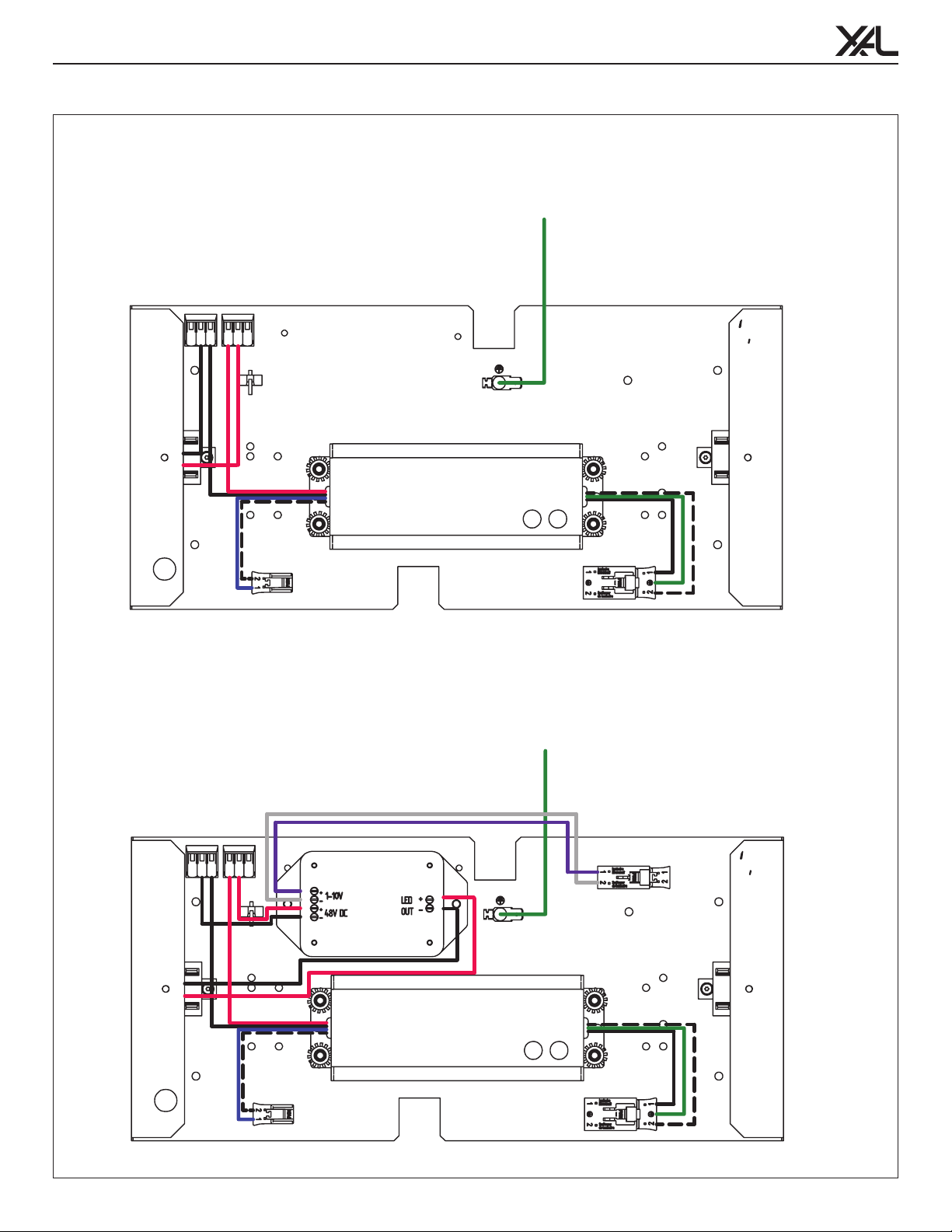
29. The LED circuit must always be closed, before the converter is connected to the main power. XAL does not assume any liability for damages resulting from nonobservance of this rule.
FR
avant de changer les lampes (si applicable) ou avant de realiser travaux (p.ex nettoyage) a la luminaire. Attendre jusqu‘à ce que la luminaire et les lampes ont frâichit completement. Merci de bien vouloir vous référer aux notes d‘installation
utiliser encore un produit de nettoyage sans alcol qui ne fraye pas le material. Garder cette notice de montage pour possibles travaux de maintenance.
3. La luminaire n‘ est pas apte pour l‘utilizage extrerieur.
4. Utilizer la luminaire seulement avec un dispositif de sécurité
5. Changer immédiatement des verres de sécurité defectes ou bien des écrans de protection.
12. Evitez tout contact de la lampe avec de produits chimiques corrosifs.
17.
23. Des LEDs sont des composants électroniques de haute qualité! Eviter tout contact direct de la surface de sorti de lumière de la LED avec les mains lors du montage ou des les travaux de maintenance de la lampe.
24.
27. La source du luminaire peut être remplace uniquement par le fabricant ou un tiers habilité.
29. Il faut que le circuit de LED soit fermé avant de connecter le convertisseur. XAL ne assume pas la garantie si cette norme ne se respecte pas.
ES La instalación, la puesta en marcha y el mantenimiento sólo deben realizarse por personal especializado considerando esta guía de instalación y todas las normas y reglamentaciones vigentes. Asegurarse de la aptitud eléctrica, mecá-
en esta (p.ej. Limpieza). Esperar hasta que se enfríen la luminaria y la lámpara completamente. Tener en cuenta las instrucciones de montaje del fabricante al colocar, cambiar y utilizar lámparas convencionales. Para la limpieza de la luminaria
3. La luminaria no es apta para utilizarla en el exterior.
4. La luminaria sólo debe accionar con un dispositivo de seguridad.
5. Cambie de inmediato los vidrios y las tapas de protección dañados.
12.
17.
23.
24.
29. El circuito LED debe ser cerrado antes de conectar el convertidor. XAL no asume garantía si esta norma no se respete.
We reserve the right to change our products at any time. Current information is available at www.xalusa.com.
Nos reservamos en todo momento el derecho de realizar cambios en nuestros productos. n nuestra página web www.xalusa.com siempre se encontrarán datos actuales.
Rev.:001/2014-12-31
The lamp is only to be operated
with its full protective covering!
L‘apparecchio necessita del relativo
vetro di protezione!
Sólo usar la luminaria con su
cobertura de seguridad completa!
Recommended room temperature: 77 °F.
Temperatura ambiente recomendada: 77 °F.
Température ambiante recommandée: 77 °F.
Use gloves.
Use guantes.
Utiliser des gants.
Don‘t touch
the LED
After Sales Service Hotline
The XAL After Sales Service Hotline
is available from Monday to Friday,
8 AM - 6 PM (EST)
Hotline: +1 203 262 9990
Email: service@xalusa.com
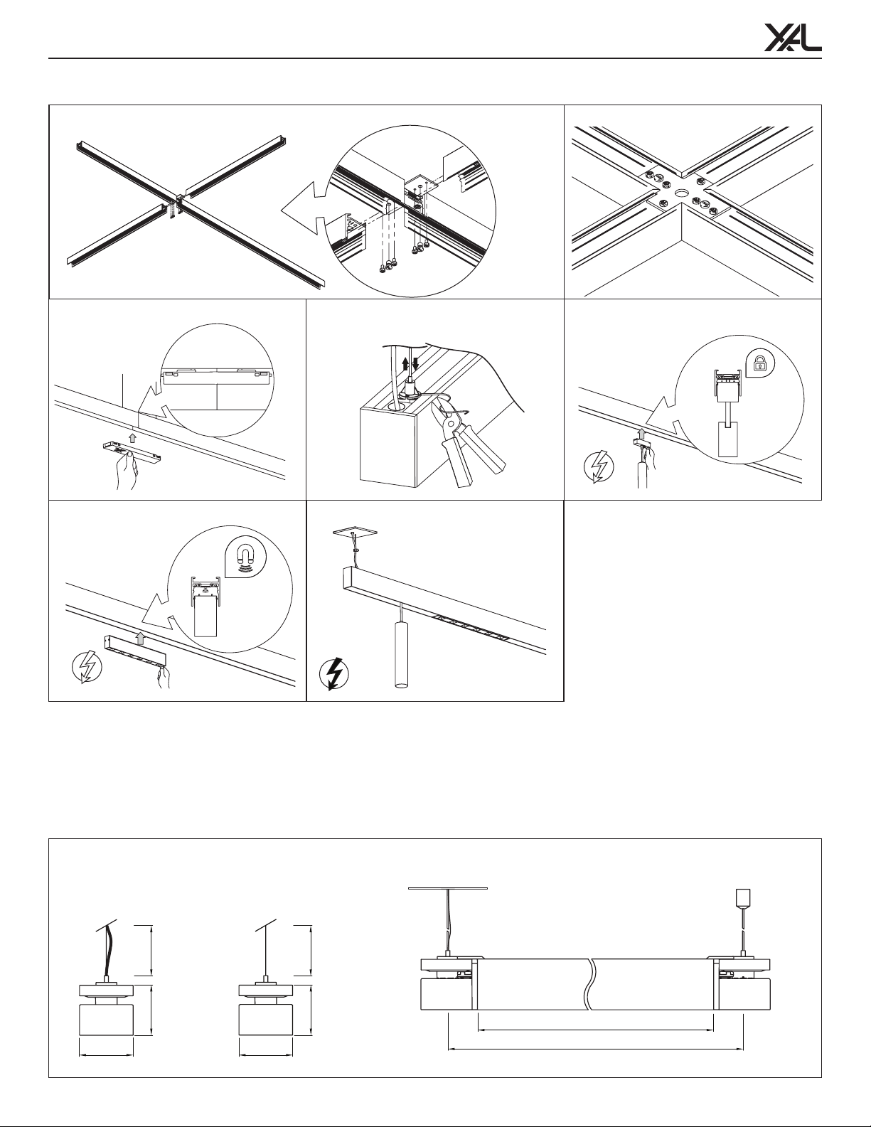
8. Adjust the
suspension
cable(s) to the
desired height
. Push
down
on
NODE
cap(s)
.
suspension cable
9. Once cable
height is set,
cut the cable
and put the
plastic NODE
cap(s) back on
MOVE IT 1.2 NODE suspended
MOUNTING INSTRUCTIONS
XAL Inc. 50 Hawley Rd. Oxford, CT 06478 T: + 203.262.9990 www.xalusa.com
MI-V2 4/13/21
15
/ 4
Other manuals for MOVE IT 1.1
1
This manual suits for next models
1
Table of contents
Other XAL Lighting Equipment manuals