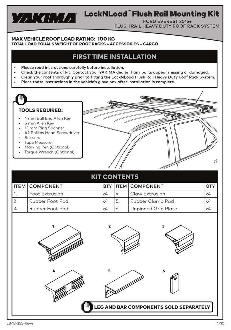
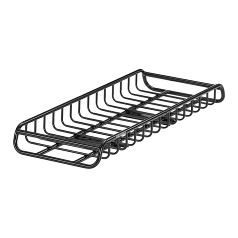
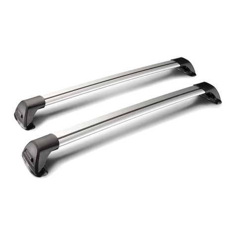
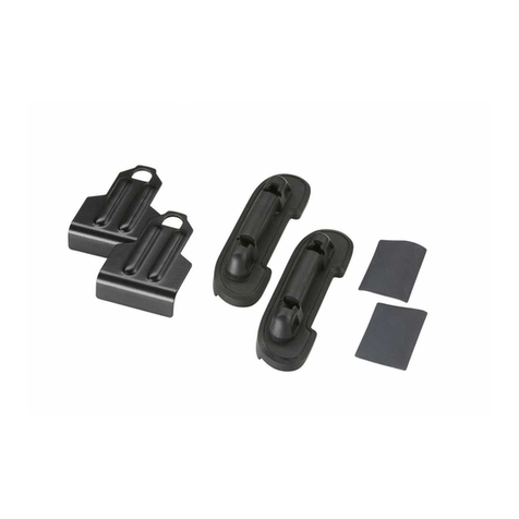
Yakima LockNLoad Track Mounting Kit User manual

28-13-010_8000316_Rev4 1/14
ITEM COMPONENT QTY ITEM COMPONENT QTY
1. Track Ranger/BT-50 Right Hand Side x1 6. Rivet x16
2. Track Ranger/BT-50 Left Hand Side x1 7. 4.9 mm Drill Bit x1
3. Track Nut Plate x4 8. M6 Hex Screw x8
4. M6 Washer x8 9. Track End Cap Front Left & Rear Right x2
5. M6 Spring Washer x8 10. Track End Cap Rear Left & Front Right x2
1
2
3
8
4
7
6
5
9
9
10
10
• Pencil
• Tape Measure
• Masking Tape
• Rivet Gun
• Drill Bit Stop
• Scissors
• Knife
• Mastic Silicone Sealant
• #2 Phillips Head Screwdriver
• Zinc Rich Cold Galvanising Coating
TOOLS REQUIRED:
• Vacuum Cleaner
• 10 mm Open Ended Spanner
• 13 mm Socket or Spanner
• Thick Cardboard Strips
• Power or Cordless Drill
• Rubber Mallet (Optional)
LockNLoad Track Mounting Kit
LNL Track Ford Ranger GEN3&GEN4 / Mazda BT-50 GEN2
Double Cab 2011+
TRACK MOUNT HEAVY DUTY ROOF RACK SYSTEM
LEG AND BAR COMPONENTS SOLD SEPARATELY
8000316
®®
MAXIMUM PRODUCT LOAD RATING: 100 kg
IMPORTANT:
• LOAD = WEIGHT OF PLATFORM or BARS + MOUNTING SYSTEM + ACCESSORIES + CARGO
• PLEASE REFER TO VEHICLE MANUFACTURER SPECIFICATIONS FOR MAX ROOF
LOAD CAPACITY OF VEHICLE. THE LOWEST LOAD RATING APPLIES.
• OFFROAD RATING: SCAN QR CODE FOR LOCKNLOAD LOAD RATING GUIDE.
REDUCTIONS MAY APPLY.
!
• Please read instructions carefully before installation.
• Check the contents of kit. Each spine has the last four digits of the kit’s part number lasered in.
Contact your YAKIMA dealer if any parts appear missing, incorrect or damaged.
• Clean your roof thoroughly prior to itting the LockNLoad RuggedLine.
• Place these instructions in the vehicle’s glove box after installation is complete.
FIRST TIME INSTALLATION
KIT CONTENTS

28-13-010_8000316_Rev4 2/14
Vehicle Front
BEFORE BEGINNING
INSTALLATION
Clean roof thoroughly
and allow to dry before
beginning installation.
TRACK ORIENTATION
The long edge of Track faces outside of vehicle
as shown, with rectangular cut outs at rear of
vehicle.
It is recommended to install one Track at a time.
The help of an assistant is required to install
Tracks. NOTE - image as viewed
from rear of vehicle
Long edge Long edge
REAR ROOF TRIM MEASUREMENT
Approximately 185 mm from the rear
of vehicle is a visible line on the roof
trim. This line will be cut in Step 5.
NOTE - image as viewed from above
Use care when drilling these
holes due to airbag location
LEFT Track
RIGHT Track
185 mm
Visible line on
roof trim
Rectangular cut out
at rear of vehicle
If you have a factory snorkel itted,
measure and mark
38 mm back from
the visible line on
roof trim as shown.
This new line will
be cut in Step 5.
38 mm
Visible line on
roof trim
Mark measurement
on trim with a pencil
Vehicle Rear
! !
TRACK INSTALLATION
1
2
3
Vehicle Rear

28-13-010_8000316_Rev4 3/14
Place thick Cardboard
Strips either side of
roof trim prior to
cutting to prevent
accidental
scratching
of the roof
body should
the knife slip.
CUT FRONT ROOF TRIM
Place Track on top of roof trim, positioning the end of track on rear trim cut line.
Measure and cut front roof trim 4 mm from front end of Track.
An additional 2 mm either end is required to it the Track End Caps.
Remove Track from vehicle.
PROTECT ROOF TRIM
Tape thick
cardboard
strips along Track
CUT REAR ROOF TRIM
Using a knife, precisely cut the
width of the rear section of roof
trim as determined from Step 3.
PEEL BACK ROOF TRIM
Using your ingers, carefully
peel back the cut section of
roof trim until the double
sided tape underneath trim
releases.
Continue to peel trim from
roof until trim and double
sided tape is off the vehicle.
It is important that any
double sided tape still on
vehicle is completely cleaned
off before Track itment.
Without Factory Snorkel With Factory Snorkel
Work trim backward and forwards to snap
stainless steel section in rubber trim
185 mm
38 mm
4 mm
45
6
7

28-13-010_8000316_Rev4 4/14
ALIGN TRACK
Place Track into roof channel, ensuring there is a 2 mm spacing
from end of trim to Track both front and rear as shown.
Apply lengths of Masking Tape along window and door seals.
This prevents drill swarf from getting caught.
APPLY MASKING TAPE
2 mm
2 mm
SPOT DRILL RIVET HOLES
With the help of an assistant, hold track down irmly in roof channel. Using
the supplied 4.9 mm Drill Bit, start spot drilling each rivet hole in the Track
from the rear of the vehicle working consecutively frontward. Ensure the
Track does not move during this process by maintaining downward pressure on
the Track. Once complete, remove Track taking care not to scratch vehicle.
Drill frontward
Vehicle Front
Vehicle Rear
8
9
10

28-13-010_8000316_Rev4 5/14
All rivet holes can now
be carefully drilled
through.
To avoid drilling into
roof lining a drill stop
must be used.
The roof skin is approx.
2-3 mm thick.
Ensure that a drilling
angle perpendicular
to the roof angle
is maintained.
APPLY PROTECTIVE SEALANTS
Stage 1
Apply liberally in and around holes. Allow to dry.
Stage 2
Apply liberally in and around holes
Stage 1
Liberally apply a Zinc Rich Cold Galvanising
Solution to the inside surface and surrounds of
each drilled hole.
Allow solution to become touch dry before
proceeding with Stage 2 (approx. 10 min
depending on product used).
Stage 2
Liberally apply a Mastic Silicone Sealant to the
inside surface and surrounds of each hole.
Drill
Stop
Warning!
Pay extra attention when
drilling these holes as this
is the location of the side
curtain airbag components
! !
11 DRILL ROOF CHANNEL
REMOVE SWARF
Avoid pushing swarf
into the newly drilled
holes by removing
swarf from roof
channel with a
Vacuum Cleaner.
Vacuum swarf
12
13

28-13-010_8000316_Rev4 6/14
END CAP FITMENT
Assemble End Caps within Tracks as shown.
The notches on the side of End Cap base must face the outside of vehicle.
Align End Cap and
slide into position
Notches face away
from vehicle
15
Align Track and secure End Caps by inserting all Rivets in their respective holes
through Track into roof channel.
Using a Rivet Gun, punch each Rivet starting from the centre Rivet, then follow the
numerical riveting order as shown.
TRACK INSTALLATION
16
8 7 312456
Vehicle Front
To secure End Caps,
insert Rivet through
End Cap and Track
PLACE TRACK BACK INTO ROOF CHANNEL
Accurately place Tracks over drilled holes in roof channel,
ensuring Track orientation is correct as shown, with rectangular
cut outs at rear of vehicle.
Long edge Long edge
14

28-13-010_8000316_Rev4 7/ 14
TRACK INSTALLATION COMPLETE
Check both Tracks are secured to the vehicle as per these installation
instructions.
For assistance contact your local Yakima dealer.
17
IF INSTALLING LOCKNLOAD ROOF RACKS, CONTINUE
ON TO STEP 18
IF INSTALLING A LOCKNLOAD PLATFORM, SWITCH
TO YOUR PLATFORM INSTRUCTIONS
!

28-13-010_8000316_Rev4 8/14
BAR INSTALLATION
INSERT NUT PLATES
Run all M6 Hex Screws through Nut Plates to remove burrs.
Insert two (2) Nut Plates into each Track as shown.
Nut Plate
21
REMOVE LEG COVERS
Using the keys supplied
in the LockNLoad Leg
Kit (sold separately),
remove all Leg Covers.
INSERT LEGS
Slide the pre-assembled Leg
assemblies into the underside
channel of LockNLoad Bars.
If Leg assemblies
will not slide in,
loosen Screws to
increase gap.
19 20
From the LockNLoad Bar
Kit (sold separately), remove
Plastite Screw from each Bar
end using a #2 Phillips Head
Screwdriver and pull out End
Caps from Bars.
Keep all parts aside for
later installation.
18 REMOVE END CAPS FROM BARS

28-13-010_8000316_Rev4 9/14
23 BAR PLACEMENT
Carefully place front Bar assembly over Nut Plates, ensuring spacing is correct
as shown in the previous Step. Take care not to damage vehicle. Position Legs
along Bar until both legs are securely positioned on Nut Plates within Track.
BAR LOCATION
IMPORTANT: Before beginning Bar installation, identify where along the Track
you want the Front and Rear Bars itted.
We recommend a minimum of 700 mm between Bars.
≥ 700 mm
22
SECURE BAR ASSEMBLY TO TRACKS
From the LockNLoad Track Kit, insert
1 x M6 Hex Screw through the two
outer holes on Legs into Nut Plate as
shown.
Loosely secure Screws using a 5 mm
ball end Allen Key.
24
=
=
ADJUST BAR OVER HANG
Use a Tape Measure to ensure even Bar overhang on each side, re-adjust if
required by sliding bar along legs.
25
NOTE - Bars require individual adjustment due to tapered
roof. Bars must be installed perpendicular to Tracks.

28-13-010_8000316_Rev4 10/14
CHECK BAR SLOT MEASUREMENTS
Place Bars on lat surface with legs facing upwards, as
shown. Take appropriate measures to avoid scratching
the product and surface.
Identify slot on each Bar end. Using a Tape Measure,
record Leg to underside slot distance of each bar in the
table (right). Ensure measurement is taken from the
centre of the Legs as shown.
XX
YY
X = X
Y = Y
28
BAR SLOT
MEASUREMENTS
Bar 1 (X)
______mm x2
Bar 2 (Y)
______mm x2
The ends of each bar should be the same
measurement respectively, if not, loosen M8
Set Screws and repeat Steps 23-28.
SECURE LEGS TO BARS
Tighten all M8 Set
Screws to 9 Nm using
a 13 mm Spanner.
26 REPEAT AND REMOVE
Repeat Steps 23 - 26 for
remaining bar assembly.
Carefully remove all Bar and
Leg assemblies from vehicle.
27

28-13-010_8000316_Rev4 11/14
SECURE END CAPS TO BARS
Insert the End Caps as shown. A Rubber
Mallet can be used to assist installation.
Secure using Plastite Screw
(from LockNLoad Bar Kit).
Tighten using a #2 Phillips
Head Screwdriver.
31 32
BAR SLOT COVERS (OUTSIDE LEG)
Measure the Bar channel outside of
the Legs and subtract 20 mm from
this measurement.
Using the remaining pieces of
Slot Cover from the previous
Step, cut to this length and
press into the underside channel
of each Bar end as shown.
30
-20 mm
BAR SLOT COVERS (INSIDE LEG)
From the LockNLoad Bar Kit, cut Bar Slot
Covers as per measurements recorded
in the previous Step and press into the
underside channel of Bar ends as shown.
NOTE - Bar Slot Covers to be
inserted with lat side visible
29

28-13-010_8000316_Rev4 12/14
Position front and rear Bars along Tracks as required, ensuring there is a minimum
distance of 700 mm between each Bar.
Measure from the centre of each Leg as shown.
34
M6 HEX SCREW ASSEMBLY
From the LockNLoad Track
Kit, assemble 1 x M6 Spring
Washer and 1 x M6 Washer
onto each M6 Hex Screw.
Insert through the outer
holes on Legs into Nut
Plates as shown.
35
BAR FITMENT
Slide Nut Plates in Track into position for Bar placement (it doesn’t have
to be exact). Place Bar assembly onto Tracks, carefully locating the four
central raised notches on base of Legs into the cut outs on Nut Plates as
shown. Take care not to damage vehicle. Repeat for remaining Bar.
33
≥ 700 mm

28-13-010_8000316_Rev4 13/14
39
38
Key Number:
FIT LEG COVERS
Using the keys and
Covers supplied
in the LockNLoad
Leg Kit, it and lock
all Leg Covers.
BAR KEYS
Place one key on the vehicle key ring
and put the other away safely, or
store with the spare vehicle key.
Write the key number (which is stamped
on the key) in the box provided.
Replacement keys are available from
Yakima stockists, visit www.yakima.com.au
or www.yakima.co.nz to ind your
nearest store or contact us directly on
1800 143 548 (AU) or 0800 4776 722 (NZ).
CHECK BAR LEGS ARE SECURE
Check all Bar Legs are secure.
SECURE BARS TO TRACKS
Tighten all M6 Hex Screws to 5
Nm using a 10 mm Open Ended
Spanner. Do not over tighten.
36 37

28-13-010_8000316_Rev4 14/14
ALL CONTENT SUBJECT TO YAKIMA AUSTRALIA PTY LTD COPYRIGHT © 2016
www.yakima.com.au
www.yakima.co.nz
www.yakima.com
www.yakima.eu
YAKIMA PRODUCTS, INC.
4101 Kruse Way
Lake Oswego, OR
97035-2541
USA
888 925 4621
YAKIMA AUSTRALIA PTY LTD
17 Hinkler Court
Brendale, QLD 4500
Australia
1800 143 548
Table of contents
Other Yakima Automobile Accessories manuals

Yakima
Yakima WheelHouse User manual

Yakima
Yakima K682 User manual

Yakima
Yakima FlipSide 4 User manual

Yakima
Yakima K984 User manual

Yakima
Yakima K152 User manual

Yakima
Yakima Mako Saddles User manual

Yakima
Yakima K960 User manual

Yakima
Yakima HullRaiser User manual

Yakima
Yakima Mo Joe User manual

Yakima
Yakima 8001133 User manual

Yakima
Yakima RailGrab 2 User manual

Yakima
Yakima Prorack K436 User manual

Yakima
Yakima EXO OpenRange User manual

Yakima
Yakima HullRaiser User manual

Yakima
Yakima K1190 User manual

Yakima
Yakima K363 User manual

Yakima
Yakima MultiMount User manual

Yakima
Yakima BOA User manual

Yakima
Yakima BigStack User manual

Yakima
Yakima ROC 4 User manual