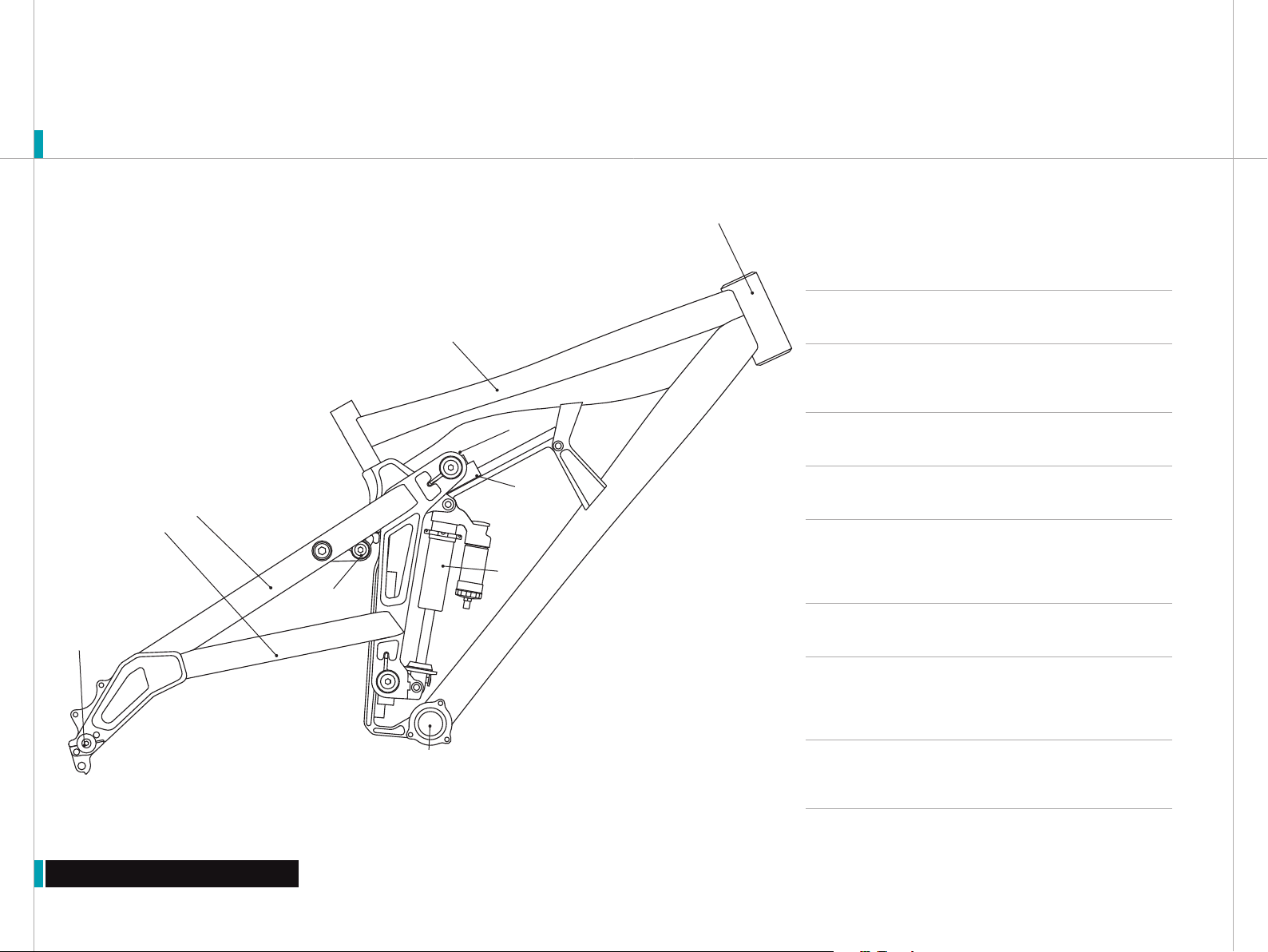
Yeti 303 DH User manual

YETI CYCLES
600 CORPORATE CIRCLE, UNIT D
GOLDEN, CO 80401
USA
303.278.6909 / 888.576.9384
www.yeticycles.com
303 DH OWNER’S MANUAL ‘06-’07

Table of Contents
Brand Overview 4
Frame Features 6
Geometry 8
Maintenance Schedule 10
Bike Setup Overview 12
Rail System Lubricationū14
Eccentric Adjustmentū16
Shock Setupū18
Shock Quick Start Guideū20
Line Setupū22
Assembly Overview 24
Assemblyū26
Exploded Views 40
Part List 42
Warranty 44
Contact Information 45

6
OVERVIEW
Overview
Warning: Make sure you review and understand the warnings, instructions, and content of this manual and
accompanying manuals for your bicycle.
Warning: Technological advances have made bicycles and bicycle components more complex and the pace of
innovation is increasing. It is impossible for this manual or the accompanying manuals to provide all the information
required to properly repair and/or maintain your bicycle. In order to help minimize the chances of an injury, it is critical for
you to have work performed by an authorized Yeti retailer.
performed by an authorized Yeti Dealer.
This manual contains many “Warnings” and
“Cautions” concerning the consequences of failure
to maintain or inspect your bicycle. The combination
of the safety alert symbol and the word “Warning”
indicates a potentially hazardous situation in which ,
if not avoided, could result in serious injury or death.
The combination of the safety alert symbol and the
word “Caution” indicates a potentially hazardous
situation in which, if not avoided may result in minor
injuries or damage to your bicycle or a component of
your bicycle. Be sure to read and understand all of
the Warnings and Cautions.
Congratulations on your purchase of a new
Yeti bicycle.We are confident your new bicycle will
exceed your expectations for value, performance and
ride quality. Each frameset and component has
been custom specified and designed to enhance your
riding experience. Whether you are a beginner
cyclist or a seasoned-pro, Yeti bicycles will provide
endless hours of two-wheeled fun.
General infOrmatiOn
This model-specific manual is designed to be
used in conjunction with the general Yeti Owner’s
Manual and the manuals supplied by the suspension
manufacturers. If you did not receive the Yeti
Owner’s Manual or the manual provided by the
suspension manufacturer, download the materials
off the Internet, or contact you dealer.
Bicycling can be a hazardous activity
even under the best of circumstances. Proper
maintenance of your bicycle is your responsibility
and when done properly helps reduce the risk of
injury and damage to your bicycle. This manual
outlines basic setup and maintenance
recommendations of your new Yeti. Because it is
impossible to anticipate every situation or condition
that may occur during the assembly, setup and
maintenance of your bicycle, Yeti recommends that
all service and repairs be

8
Frame Features
FEATURES
1. PURE TUBING
Yeti Pure tubing is custom butted and tapered 7005 aluminum.
This makes the frame lightweight and strong without the use of
gussets. Unique shape provides added strength at the head tube
junctions.
2. BOTTOM BRACKET
83 mm shell, for use with a 128 mm spindle
3. SEATSTAY (A) + CHAINSTAY (B)
Square seatstays are stiff and strong. Elevated chainstays
provide chainring clearance. Accommodates a 2.7” tire.
4. THROUGH AXLE
12/15mm through axel spaced at 150mm. Allows for a stiff and
strong rear end.
5. SHOCK
9.5” eye-to-eye / 3.0” stroke.
6. LINEAR RAIL SYSTEM
The linear block contains four rows of ball bearings that circulate
along the rail allowing the guide to move freely. The linear rail
has an armalloy surface for corrosion protection and wear.
7. MONOCOQUE TOP TUBE
Boxed form allows for a stiff and light construction.
8. ECCENTRIC MOUNT
Eccentric mount allows for adjustable geometry. The head angle
and bottom bracket height can be adjusted from 64˚/14.0” to
66˚/15.0”.
9. STABILIZING LINK
Stabilizing link translates the rear wheel load directly into the
main frame. Allowing the shock and rail system to function under
less force.
1
7
4
5
2
3b
8
3a
6
9

10
Geometry
GEOMETRY
GEOMETRY 303 DH
S M L
A 16.75 16.75 16.75
B 22.00 23.00 24.00
C 66-64 66-64 66-64
D 58 58 58
E 17.60 17.60 17.60
F 46.75-46.25 46.75-46.25 46.75-46.25
G 14.0-15.0 14.0-15.0 14.0-15.0
H 30.50-31.00 30.50-31.00 30.50-31.00
I 4.50 4.50 4.50
B
G
F
E
A
C
I
H
D
*All measurements are in inches

12
Maintenance
MAINTENANCE
MAINTENANCE Following these guidelines will help maintain the performance of your bicycle and prevent
more serious problems from arising. It is important to remember that service intervals can vary depending
on climate, trail conditions, and riding frequency.
Caution: The torque specications listed should be used as a guide when performing maintenance. Technological
advances have made bicycles and bicycle components more complex, and the pace of innovation is increasing.
Because of these advances, YETI recommends that you refer to the torque specications of the manufactures
component you are adjusting. In order to help minimize the chances of an injury, do not perform any maintenance that
you are not condent can be completed within your abilities.
MAINTENANCE? Not sure how to work on your own bike?
Contact your authorized Yeti dealer or visit www.parktool.com
and check out the repair help section. This section contains
detailed instruction on many of the service items listed in the
maintenance schedule.
TORQUE We have attached a brief list of torque specifications for bolts and components that may need to be
tightened while performing basic maintenance. This is just guide. For specific torque specifications, please
contact the component manufacturer directly.
TORQUE SPECS
Swingarm Pivot Pins
40
-
50
Stabilizer Pinch Bolts
40 -50
Titanium Pivot Bolts
125 -150
Pivot Pins
125 - 150
Through Axle Bolts
125 -150
Cable Guide Screws
10 -15
Derailleur Hanger Bolts 30 -45
Handlebar Binder Bolt 150 -180
Stem Binder Bolt 175 -260
Seatpost Binder Bolt 150 -180
Saddle Clamp Bolts 175 -250
Rear Derailleur 70 -86
Chainring Bolts 88 -132
ACTION EVERY RIDE MONTHLY 3 MONTHS ANNUALLY
Lube linear block (see page 14) x
Clean and lube chain x
Check tire pressure x
Clean bike of mud and debris (never
spray water directly into frame or
components)
x
Check shock pressure x
Check for loose bolts and tighten if
necessary
x
Check headset and tighten/loosen if
necessary
x
Thoroughly clean pivot points with a
rag (do not lubricate)
x
Replace brake pads if necessary x
Check tires for wear x
Check spoke tension, and retention if
necessary
x
Check chain for worn, damaged, or
loose links. Replace chain if necessary
x
Complete tune-up performed by an
authorized YETI dealer
x

14
Bike Setup
SETUP
TOOLS NEEDED
Shock Pump
Tape Measure
4mm allen key
Lubrication Syringe
White Lithium Grease
4mm allen key
5mm allen key
1.5mm allen key
TIME
30-45 minutes
YETI TIPS
Inspect your shock for any visible damage. If
oil is leaking or you notice any damage to the
surfaces or seals, please contact the Fox Racing
Shox service center for repair.
Removing the shock from the linkage will
require the Yeti linkage tool for proper assembly
and disassembly. The tool can be purchased
online www.yeticycles.com or through an
authorized YETI dealer.

16
Rail System Lubrication
SETUP RAIL SYSTEM LUBRICATION
RAIL LUBRICATION Fill the supplied syringe with white lithium
grease. This is best done by removing the plunger on the syringe and
packing it with the grease. Once the syringe is filled, press the end of the
rubber line onto the grease port as shown. Compress the syringe to force
grease into the rail system.
Warning: The rails system must be lubricated after every ride. Failure to
lubricate based on the specications can cause permanent damage to the linear
rail.
SETUP OVERVIEW Both the rail and block are made from proprietary carbon steel. The rail is then case
hardened to between 58 and 64Rc. An Armalloy surface treatment is applied to the rail and the block for
corrosion protection and wear resistance. The ball bearings are made from martensitic stainless steel -
which is equal to a 440 stainless. End scrapers, end seals, inner seals, and side seals prevent contaminants
from entering the system.
There is also a custom grease port on the end of each block. Grease should be applied with the supplied
applicator after the days ride and/or bike wash. After grease application, the suspension needs to be cycled
6-10 times to spread the grease evenly throughout the bearing raceways and ports in the block
1
RAIL LUBRICATION After you have completed the initial lubrication.
Weight and unweight the bike to compress the shock an actuate
the rail system. If you see residual grease left on the rail after cycling
the suspension you have sufficiently lubricated the system. If no grease
is visible after cycling repeat Step 1 until residual grease is visible on the
rail after cycling. Perform this lubrication for both the top and main rail
systems. Wipe off any excess grease on the rail before riding.
1

18
Eccentric Adjustment
SETUP GEOMETRY
ECCENTRIC ADJUSTMENT Slightly loosen the eccentric mount bolts
with a 5mm allen key. The bolts only need to be just loose enough to
spin the Eccentric.
SETUP OVERVIEW The 303 DH has the ability to change the geometry of the bike via the eccentric mount.
The geometry can be adjusted from a 64 degree head angle / 14 inch bottom bracket height through a 66
degree head angle / 15 inch bottom bracket height.
1
ECCENTRIC ADJUSTMENT Place a 6mm allen key into the pivot pin
as shown. Rotate the eccentric to the desired position. The eccentric
adjustment has a range of 64˚/14” - 66˚/15”.
2
ECCENTRIC ADJUSTMENT Once the eccentric mount is in the desired
position secure the mounting bolts.
Torque: 125-150 inch/lbs
3

20
Shock Setup
SETUP SHOCK DHX 5.0
REBOUND The rebound adjustment has a 14-click range. Adjustments
that are too fast (counter-clockwise adjustment) will produce a
springy ride with excessive kick up of the rear end causing a bucking
sensation. Adjustments that are too slow (clockwise adjustment) will cause
packing of the rear wheel that is identified by a sluggish ride feeling.
Slower rebound - turn the adjuster clockwise
Faster rebound - turn the adjuster counter-clockwise
6
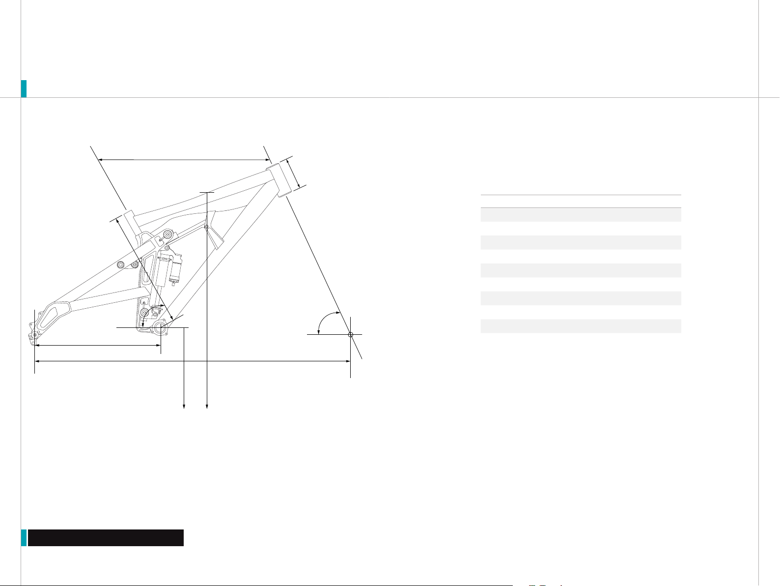
SAG SETUP Use 25-35% of the shocks stoke for downhill use. To
determine sag, first measure the distance between the centers of
each shock mounting bolt (eye-to-eye) and record this number. Make sure
you have the correct spring for your weight. See the spring rate chart.
>2006 303 DH eye-to-eye 9.5”
4
WHAT IS PRO-PEDAL? Pro-Pedal is compression tune that
gives the right amount of low speed compression to filter out
unwanted rider induced bob without sacrificing critical mid
and high speed damping. No flushing through your travel,
no wasted setup time, and no energy sucking suspension
movement, just super efficient pedaling performance ready
for hits of any size.
PRO-PEDAL The Pro-Pedal adjustment has a 15 click range of
adjustment. The Pro-Pedal damping affects the first half of stroke.
More Damping - clockwise rotation
Less Damping - counter-clockwise rotation
BOTTOM-OUT RESISTANCE The bottom-out adjuster has 3 full turns
of adjustment . This adjustment controls the bottoming resistance of
the shock, meaning it controls the compression on final part of the shocks
stroke. The adjuster can be turned by hand or with a 4mm allen key. The
allen key should be placed into one of the holes on the perimeter of the
adjuster.
More Resistance - clockwise rotation
Less Resistance - counter-clockwise rotation
Warning: When the volume adjuster has reached its counter-clockwise
stop limit, continued force on the adjuster may cause damage to the adjuster
mechanism.
BOOST VALVE The DHX 5.0 has an air pressure range of 75-200
psi, and it must be pressurized. The Boost Valve allows the Pro-
Pedal (beginning compression) and the Bottom-Out Resistance (ending
compression) to work seamlessly together. Because of this relationship the
Boost Valve pressure affects both the Bottom-Out Resistance and the Pro-
Pedal Adjustments (see adjustment relation).
Lower pressures (75-100 psi) - will decrease bottoming resistance and
Pro-Pedal at a given setting.
Higher pressures (110-200 psi) - will increase bottoming resistance and
Pro-Pedal at a given setting
SAG SETUP Next, sit on the bike and record the new (eye-to-eye)
measurement. Subtract the static eye-to-eye measurement from this
new measurement and you get your sag in inches. An easy way to calculate
sag is to multiply the shock travel by your desired sag percentage. See
quick setup guide on page 20.
5
Warning: Use of the shock with improper air pressure can cause a loss
of dampening and shock malfunction could occur. Do not attempt to turn the
adjuster with more than 125 psi in the chamber..
SETUP OVERVIEW The DHX 5.0 employs both speed sensitive rebound damping and position sensitive
compression damping. There are three external adjustments that affect the compression and one external
adjustment for the rebound. The three compression adjustments are the Bottom-Out Resistance, Boost Valve
and Pro-Pedal. The Pro-Pedal controls the anti-bob properties of the shock or the first part of the shocks
stroke, the Bottom-Out Resistance affects the end of the shocks stroke, and the Boost Valve damping links
these two adjustments together to create a seamless transition through the entire stroke. The Boost Valve
also de-couples the Pro-Pedal and Bottom-Out Resistance making these adjustments independent on each
other.
1
2
3

22
SETUP QUICK START GUIDE
Quick Setup Guide
QUICK START GUIDE DHX 5.0 303 DH
Rebound 10 Clicks
Bottom-Out Resistance 1 Turn
Pro-Pedal 2 Clicks
Boost Valve 125 psi
SAG SETTINGS
Sag % 25 30 35
Eye-To-Eye (inches) 8.750” 8.600” 7.95”
*All Clicks are clockwise rotation from all the
way out or a full counter-clockwise position.
SPRING WEIGHTS - RECOMMENDED 303 DH
SPRING CHART (IN/LBS)
400 450 500 550 600
Min. rider weight (lbs) 125 130 150 205 245
Max. rider weight (lbs) 150 190 215 250 275

24
SETUP OVERVIEW The 303 DH has full cable housing. Utilizing full cable housing helps prevent corrosion
from the elements and keeps the shifting smoother for a longer period of time. The 303 DH also has custom
guides that allows the cables to slide when the bike is compressed.
Line Setup
SETUP CABLE ROUTING
Caution: The failure to properly route shifter housing can cause malfunction of the shift mechanism and unexpected
shifting of gears
LINE SETUP The first step in the rear derailleur line setup is to cut the
proper length housing. The housing runs from the rear shifter along
the drive side of the bike, down the seatstay, and into the derailleur stop. If
the housing is to long it will sag and rub on the lower crown of the fork
LINE SETUP Once you have the proper length housing install the IGUS
I Glide Clips as shown. The flange of each clip should be placed on the
end of the cable guide.
LINE SETUP Install the top cable guide and screw the M2.5x.45x.8
flat head bolt using a 1.5mm allen key. Repeat this process onthe
opposing side for the rear brake.
Torque: 10-15 inch/lbs
1
2
3

26
Assembly
ASSEMBLY
TOOLS NEEDED
Warning: Service on Yeti bicycles requires special
knowledge and tools. Yeti Cycles recommends that all
service and repairs be performed by an authorized Yeti
Dealer
Dead blow hammer
14mm socket
Two - 5mm allen keys
6mm allen key
4mm allen key
3mm allen key
8mm allen key
White Lithium Grease
Blue Loctite
Ti Prep
TIME
30-45 minutes depending
on condition of the bike
YETI TIPS
Make sure your tools are in good condition. A
worn allen key can round the hex on a bolt not
allowing for proper torque.
Torque settings are listed throughout the
instructions. It is also import to prep all bolt
threads . The instruction denote wether to use a
blue Loctite compound or grease.
The linkage tool is necessary to properly
disassemble and reassemble the linkage. Using
a hammer to tap out the pin can cause damage
to the linkage and shock.
Not every too may be needed for the assembly/
disassembly of your bike. The list encompasses
all the tools necessary to complete assembly/
disassembly on each bike

28
ASSEMBLY
Sub Assembly
TOP RAIL SUBASSEMBLY Apply loctite to the four M5x.8x12 socket
caphead mounting bolts.
TOP RAIL SUBASSEMBLY Make sure the grease port is at the opposite
end the square opening of the Top Rail Mount as shown.
TOP RAIL SUBASSEMBLY Screw all four of the bolts into the rail using
a 4mm allen key.
Torque: 125-150 inch/lbs
TOP RAIL SUBASSEMBLY Place the Eccentric Base onto the Linear
Block. Make sure to place the shorter tab of the Eccentric Base
towards the grease port as shown.
TOP RAIL SUBASSEMBLY Place the Eccentric on the Eccentric Base.
Make sure you position the stops as shown.
THREAD PREP Yeti recommends prepping all threads with
Loctite or grease. The medium strength (blue) formula along
with proper torque is ideal for keep the bolts snug.
TOP RAIL SUBASSEMBLY Place the rail system onto the Top Rail
Mount as shown.
TOP RAIL SUBASSEMBLY Place the Eccentric Clamp onto the
Eccentric. Apply loctite to the four 6x1x18mm socket caphead
mounting bolts, and tighten them into the Eccentric Base using a 5mm
allen key.
Torque: 125-150 inch/lbs
MAIN RAIL SUBASSEMBLY Place the Main Pivot Mount onto the rail
as shown. Make sure the threaded mount is positioned away from
the grease port. Apply loctite to the two M6x1x8 button caphead bolts and
tighten down using a 4mm allen key.
Torque: 125-150 inch/lbs
7
8
1
3
2
4
5
6

30
Sub Assembly Cont.
ASSEMBLY
STABILIZING LINK SUBASSEMBLY Apply ti prep to the M6x1x12 Ti
Male Bolt.
STABILIZING LINK SUBASSEMBLY Attach the Ti Male Bolt and Pivot
Pin Washer to the 12mm x 42mm Pivot Pin and tighten using a 5mm
and 6mm allen keys.
Torque spec: 125-150 inch/pounds.
STABILIZING LINK SUBASSEMBLY Place the 38802 2RS Max
Bearings into the tail of the Stiff Link H, make sure the extended race
is pointing outwards. Slide the 12.7mm x 7mm Pivot Pins into the bearings
as shown. Screw the M4x.7x16 socket caphead mounting bolts into the link.
Just torque lightly so the bearing and pin assembly does not fall out of the
link. The final torque application will take place at a later step.
13
SHOCK LINK SUBASSEMBLY Place the Shock Mount onto the lower
end of the shock as shown. Slide the 8mm x31.75mm Ti Female Bolt
and 8.5mmID x 12.5mmOD washer through the shock mount and shock
eyelet.
14
STABILIZING LINK SUBASSEMBLY Place the 38802 2RS Max
Bearings into the Stiff Link H as shown. Make sure the extended race
of the bearings points inward. Repeat on the opposing side
STABILIZING LINK SUBASSEMBLY Place the Stiff Link I between the
bearings. Slide the 12mm x 42mm Pivot Pin through the bearings and
the Stiff Link I. Screw the M5x.8x10 socket caphead mounting bolts into the
Stiff Link I, do not torque the bolts. The torque application will take place at
a later step.
SHOCK LINK SUBASSEMBLY Apply ti prep to the M6x1x12 Ti Male
Bolt.
15
SHOCK LINK SUBASSEMBLY Attach the M6x1x12 Ti Male Bolt and
6.5mmID x 12.5mmOD washer to the female bolt and tighten using
two 5mm allen keys. Don not fully torque the complete torque will take
place at a later step.
16
TI PREP Yeti recommends prepping all titanium threads with
ti prep.
11
12
9
10

32
Main Assembly
ASSEMBLY
MAIN ASSEMBLY Swing the front of the Top Rail subassembly into
position on the front mount.
MAIN ASSEMBLY Lineup the through holes and slide the 8mm x
44mm Ti Female Bolt and 8.5mmID x 12.5mm OD washer into the
frame and rail mount.
MAIN ASSEMBLY Take the Top Rail sub assembly with the grease port
pointing towards the non-drive side of the frame an tap the back of
the sub assembly into the rear mount.
MAIN ASSEMBLY Line up the through holes on the frame and rail
mount and slide the 8mm x44mm Solid Ti Female Bolt and 8.5mmID
x 2.5mmOD washer through the assembly. Do not attach the opposing male
bolt, the female bolt stays in this configuration only temporarily until a later
step.
19
20
17
18
MAIN ASSEMBLY Attach the Main Rail subassembly to the frame with
the M5x.8x16 socket caphead bolts. Tighten using a 4mm allen key.
Make sure you prep the bolts with loctite.
Torque spec: 125-150 inch/pounds.
MAIN ASSEMBLY Screw the M5x.8x14 socket cap head bolts into the
frame as shown. Don not torque the bolts down, that will take place at
a later step.
MAIN ASSEMBLY Apply ti prep to the M6x1x12 Ti Male Bolt. Slide the
6.5mmID x 12.5mmOD washer onto the bolt and tighten using two
5mm allen keys.
Torque spec: 125-150 inch/pounds.
MAIN ASSEMBLY Place the Main Rail subassembly onto the frame as
shown.
23
24
21
22

34
Main Assembly Cont.
ASSEMBLY
MAIN ASSEMBLY The bearings should be positioned as shown for
proper alignment.
MAIN ASSEMBLY Align the Stabilizing Link subassembly in to
position between the bearings as shown. Tap the 12.7mm x 42mm
Pivot Pin through the bearings and the link.
MAIN ASSEMBLY Tap the 38802 2RS Max Bearings into the frame as
shown with the dead blow hammer. Make sure the extended race in
pointing inward.
MAIN ASSEMBLY Tap the bearings with the 14mm socket to slightly
recess them into the frame.
27
28
25
26
MAIN ASSEMBLY Tap the lubricated pivot pin into the frame with a
dead blow hammer. Repeat this process for the second bearing mount
on the swingarm.
MAIN ASSEMBLY Screw the pivot pin into the eccentric using a 5mm
allen key, stop once you have a few threads started. Then proceed to
the lower bearing mount.
MAIN ASSEMBLY Apply ti prep to the M6x1x12 Ti Male Bolt. Screw the
bolt and washer onto the pin as shown and tighten using a 5mm and
6mm allen keys.
Torque spec: 125-150 inch/pounds.
MAIN ASSEMBLY Lubricate the 17mm x 7.5mm Pivot Pin.
31
32
29
30

36
Main Assembly Cont.
ASSEMBLY
MAIN ASSEMBLY Place the Swingarm Spacer - Stiff Link onto the
pivot pin and lubricate the threads of the pivot pin.
MAIN ASSEMBLY Loosen the bolts on the Stiff Link H to release the
bearing and pivot pin. Rotate the link into position so the through
holes line up and slide the bearing, washer, and pivot pin in the through
hole. Making sure to keep the bearing flush with the face of the Stiff Link H.
MAIN ASSEMBLY Screw the pivot pin in a few turns, and then return
to the upper pivot mount and make a few turns. Repeat this back and
forth process until the swingarm is fully secure. Repeat this process for the
opposing side.
Torque spec: 40-50 inch/pounds.
MAIN ASSEMBLY Lubricate the through holes on the swingarm.
35
36
33
34
MAIN ASSEMBLY Push the solid ti bolt out of the rail mount and
frame. Place the shock subassembly into position as shown and slide
the solid ti bolt back into position through the frame, rail mount, and shock.
MAIN ASSEMBLY Screw a M6x1x12 Ti Male Bolt and 6.5mmID x
12.5mmOD, into the bolt and tighten using two 5mm allen keys.
Torque spec: 125-150 inch/pounds.
MAIN ASSEMBLY Slide the Swingarm Insert - Stiff Link through the
swingarm bore.
MAIN ASSEMBLY Tighten the pivot pin together using the 6mm and
8mm allen keys.
Torque spec: 40-50 inch/pounds.
39
40
37
38

38
Main Assembly Cont.
ASSEMBLY
MAIN ASSEMBLY Slide the Axle Insert in the outside face of the rear
drops as shown, Make sure the flanged end of the insert is facing
outwards. Repeat for the opposing side.
MAIN ASSEMBLY Screw M6x1x12 Ti Male Bolt and Axle Cap onto the
12mm x 150mm Axle. Make sure to apply ti prep to the threads.
Torque spec: 125-150 inch/pounds.
MAIN ASSEMBLY Secure the lower shock mount to the swingarm
using the M5x.8x12 and M5x.8x14 socket cap head bolts. The shorter
of the two bolts the M5x.8x12 is used for the upper mounting hole and
M5x.8x14 is used for the lower mounting holes. Remember to use loctite on
the threads and tighten using a 4mm allen key.
Torque spec: 125-150 inch/pounds.
MAIN ASSEMBLY Now you can fully torque the lower shock mount
bolt that was only temporarily secured from the shock subassembly.
Use two 5mm allen keys to tighten.
Torque spec: 125-150 inch/pounds.
43
44
41
42
MAIN ASSEMBLY Use two 5mm allen keys and tighten the axle down.
Torque spec: 125-150 inch/pounds.
MAIN ASSEMBLY Tighten the pinch bolts on the dropouts using a
5mm allen key. Repeat for the opposing side.
Torque spec: 125-150 inch/pounds.
MAIN ASSEMBLY Slide the axle subassembly into the frame as
shown. Use either your wheel or the spacing tube shipped with the
frame as the 150mm rear wheel spacing.
MAIN ASSEMBLY Screw M6x1x12 Ti Male Bolt and Axle Cap onto the
axle. Make sure to apply ti prep to the threads.
47
48
45
46

40
Main Assembly Cont.
ASSEMBLY
MAIN ASSEMBLY The final bolts to secure on the link are the Stiff
Link H pinch bolts. Make sure that the tail ends of Stiff Link H are
centered the bearings as shown before tightening.
MAIN ASSEMBLY Once the Stiff Link H is centered, tighten the pinch
bolts using a 3mm allen key.
Torque spec: 40-50 inch/pounds.
MAIN ASSEMBLY After the axle is secure and the rear spacing is
150mm, you can tighten the pinch bolts on the Stabilizing Link. Start
with the bolts on the main frame. Make sure the link is centered between
the bearings and the frame and tighten using a 4mm allen key.
Torque spec: 40-50 inch/pounds.
MAIN ASSEMBLY Next, tighten the bolts on the Stiff Link I using a
4mm allen key.
Torque spec: 40-50 inch/pounds.
51
52
49
50
MAIN ASSEMBLY The final steps are to tighten the pinch bolts on the
swingarm. Locate the bolts near the bearings and secure using a
5mm allen key.
MAIN ASSEMBLY Repeat this step for both locations and the opposing
swingarm.
Torque spec: 125-150 inch/pounds.
53
54
Warning: This step should only take place once the axle is secured and the
rear wheel spacing is 150mm
Warning: This step should only take place once the axle is secured and the
rear wheel spacing is 150mm
Warning: The Stiff Link H must be centered over the bearings of the
stabilizing link may not function properly.
Warning: This step should only take place once the axle is secured and the
rear wheel spacing is 150mm
Table of contents
Other Yeti Bicycle manuals