16
Setup-Fox RP23
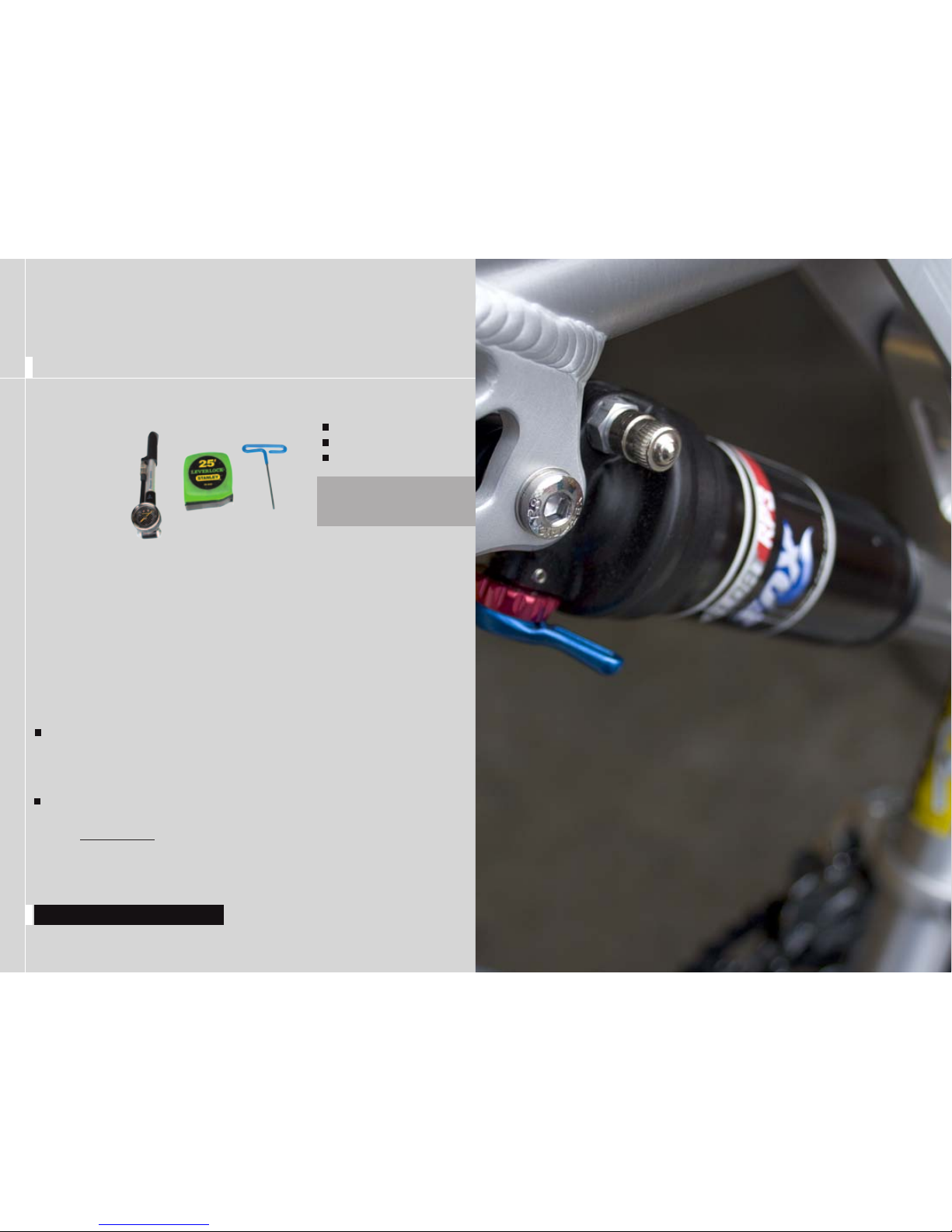
SETUP SHOCK RP23
Setup-Fox DHX Air
PRO-PEDAL The pro-pedal dampening has two settings and three
levels of adjustment and is controlled by the blue lever (formerly
the lock-out lever). The two settings are open and propedal. Use each
setting to adjust the shock for different riding conditions and situations. For
example use propedal for riding to the top of the mountain and then switch
to open for the descent.
The pro pedal knob has three different levels of dampening: (1) light, (2)
medium and (3) heavy pro-pedal. If the bike feels too firm, put it on a light
setting, and if it feels too sluggish, turn it to the stiffer setting.
AIR PRESSURE The main air spring controls the sag of the shock.
For the 575 to ride properly it is important to setup the shock with the
correct amount of sag. For general riding use 20-30% of the shock stroke
(5mm to 10mm). To increase sag reduce the main spring air pressure. To
reduce sag increase the main spring air pressure. Refer to the quick start
guide to get your starting air pressure.
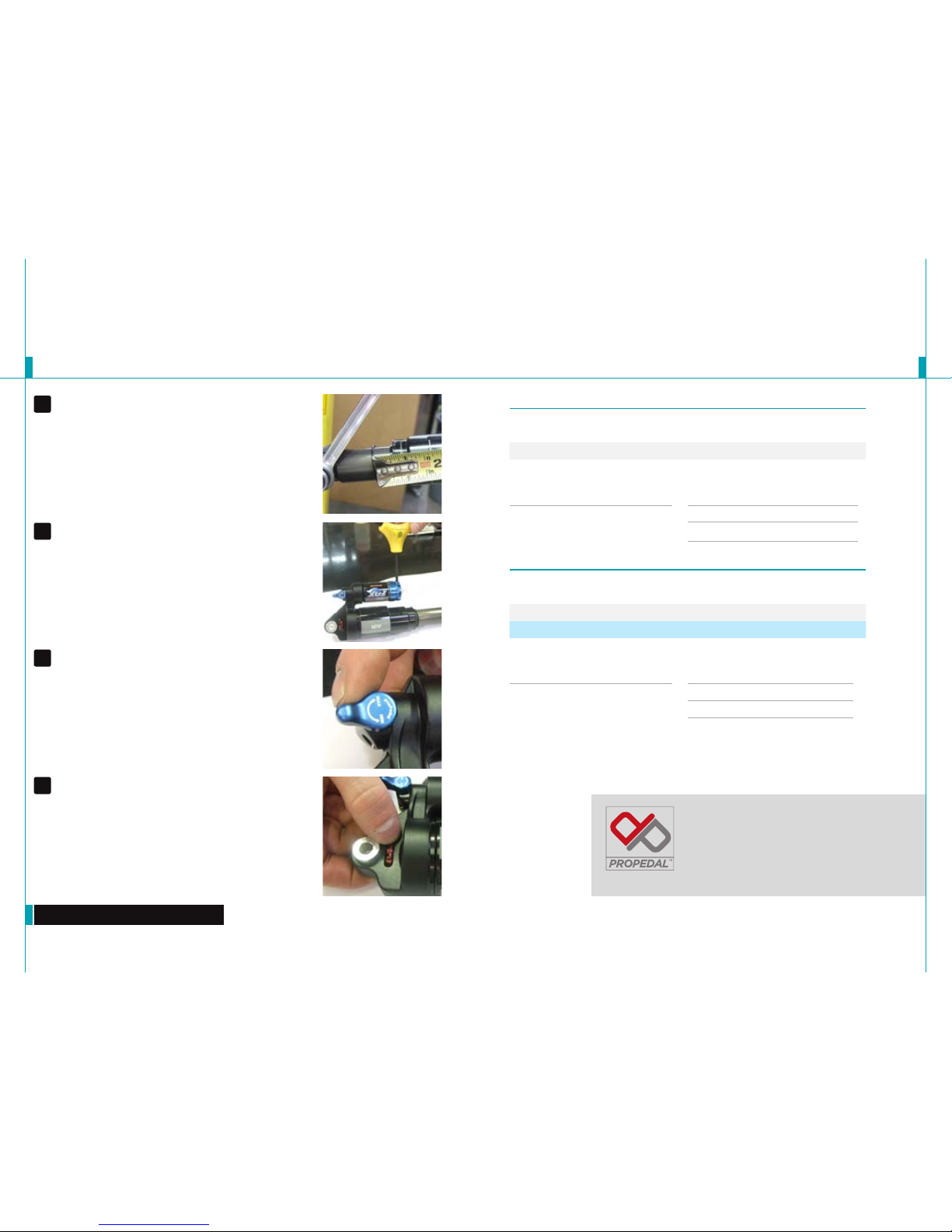
SAG Once you have set your baseline air pressure you need to
measure the sag. To measure the sag slide the travel indicator
(O-Ring) up against the shock body. With a friend supporting the bike, sit
on the saddle (do not bounce) and allow your body weight to compress
the shock. Once you have compressed the shock, get off the bike and
measure the distance between the shock body and the new position of the
travel indicator (O-Ring). This is your sag. Refer to the guide below for the
percentage of sag equivalents for the measurement recorded.
Firm ride- 20-25% sag // Plush ride- 30% sag
REBOUND The rebound adjustment has 8-10 clicks of adjustment.
The rebound knob is the red adjustment dial located above your blue
pro-pedal adjustment lever. As a general rule, adjustments that are too fast
(counter-clockwise adjustment) will produce a springy ride with excessive
kick-up of the rear end causing a bucking sensation. Adjustments that
are too slow (clockwise adjustment) will cause packing of the rear wheel
indicated by a sluggish ride feeling ride.
Slower rebound- turn the knob clockwise
Faster rebound- turn the knob counter-clockwise
4
SETUP OVERVIEW The DHX 5.0 employs both speed sensitive rebound damping and positive sensitive
compression damping. There are three external adjustments that affect the compression and one external
adjustment for the rebound. The three compression adjustments are bottom-out resistance, boost valve and
pro-pedal. The pro-pedal controls the anti-bob properties of the shock or the first part of the shock’s stroke;
the bottom-out resistance controls the end of the shock stroke; and the boost valve damping links these
two adjustments together to create a seamless transition through the entire stroke. The boost valve also
decouples the pro-pedal and bottom-out resistance making these adjustments independent of each other.
AIR PRESSURE The main air spring controls the sag of the shock.
For the 575 to ride properly it is important to setup the shock with
the correct amount of sag. For general riding use 20-30% of the shock
stroke. To increase sag reduce the main spring air pressure. To reduce sag
increase the main spring air pressure. Refer to the quick start guide to get
your starting air pressure.
Firm Ride - 20-25% sag
Plush ride - 30% sag
1
Warning: Use of the shock with improper air pressure can cause loss of
dampening and malfunction of the shock.
BOOST VALVE The DHX 5.0 has an air pressure range of 125-200 psi,
and it must be pressurized for the shock to work properly. The Boost
Valve allows the Pro-Pedal (beginning compression) and the Bottom-Out
Resistance (ending compression) to work seamlessly together. Because
of this relationship the Boost Valve pressure affects both the Bottom-Out
Resistance and the Pro-Pedal Adjustments (see adjustment relation).
Lower pressures (125 – 150 psi)- Will decrease bottoming resistance and
lessen pro-pedal stiffness at a given setting.
Higher pressures (160 – 200 psi)- Will increase bottoming resistance and
stiffen pro-pedal at a given setting.
Warning: Use of the shock with improper air pressure can cause a loss
of dampening and shock malfunction could occur. Do not attempt to turn the
adjuster with more than 125 psi in the chamber.
2
1
2
3