10
ZAPTEC Column Premium
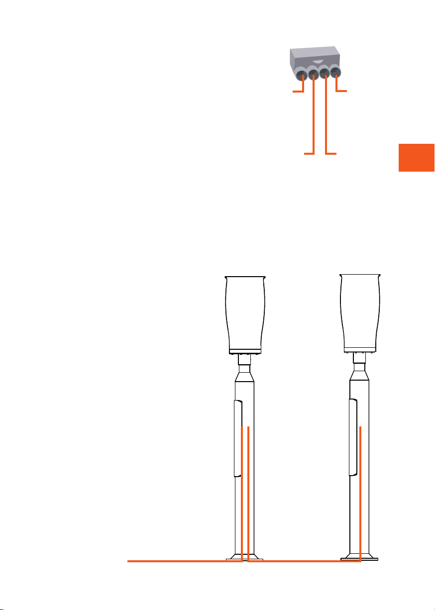
Inclus dans la colonne
1x SmartKey Column
1x Clé pour le couvercle frontal
1x Boîte de connexion Abox-i 160 L
1x Rail DIN de 35 mm, long de 160 mm
3x Borne de raccordement ALU/CU 50 mm2
double grise
1x Borne de raccordement ALU/CU 50 mm2
double bleue
1x Borne de raccordement ALU/CU 50 mm2
double g/g
4x vis et écrous M4 (les vis ne sont fournies
qu’avec la colonne double)
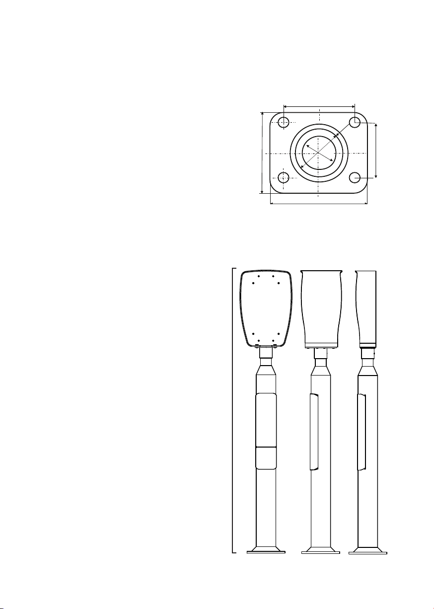
Montage de la colonne au sol
Le montage au sol est aisé grâce aux
4 trous de boulon dans le bas (embase)
pour le support standard CC160.
1500mm
1
A
2 3 4 5 6 7 8
1 2 3 4 5 6 7 8
B
C
D
E
F
A
B
C
D
E
F
Dept. Technical reference Created by Approved by
Document type Document status
Title DWG No.
Rev. Date of issue Sheet
18.10.2017
1/1
Zaptec Ladesøyle Single - v3.2
Fredrik Ostrem
112,9mm
1
A
2 3 4 5 6 7 8
1 2 3 4 5 6 7 8
B
C
D
E
F
A
B
C
D
E
F
Dept. Technical reference Created by Approved by
Document type Document status
Title DWG No.
Rev. Date of issue Sheet
18.10.2017
1/1
Zaptec Ladesøyle Double - v3.2
Fredrik Ostrem
116mm
210mm
1
A
2 3 4 5 6 7 8
1 2 3 4 5 6 7 8
B
C
D
E
F
A
B
C
D
E
F
Dept. Technical reference Created by Approved by
Document type Document status
Title DWG No.
Rev. Date of issue Sheet
18.10.2017
1/1
Zaptec Ladesøyle Double - v3.2
Fredrik Ostrem
285mm
82
180
160
160
230
230
Premium Column
Schéma de l’embase