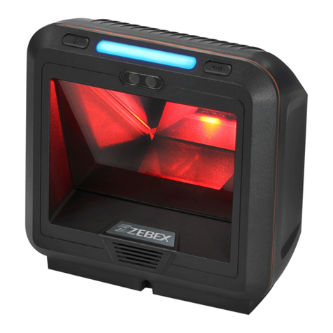
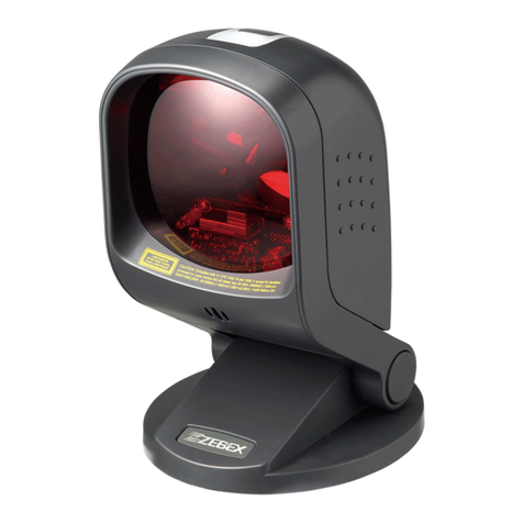
Zebex Z-6181 User manual

Dual-Laser Omnidirectional In-Counter Scanner
1


Dual-Laser Omnidirectional In-Counter Scanner
i
Revision History
Changes to the original manual are listed below:
Version Date Description of Version
1.0 July. 20, 2010 Initial release
1.1 March. 21, 2011 Added EAS connection

Dual-Laser Omnidirectional In-Counter Scanner ii
Important Notice
No warranty of any kind is made in regard to this material, including, but not limited to, implied
warranties of merchantability or fitness for a particular purpose. We are not liable for any errors
contained herein or incidental or consequential damages in connection with furnishing,
performance or use of this material.
No part of this document may be reproduced, transmitted, stored in a retrieval system, transcribed,
or translated into any language or computer language in any form or by any means electronic,
mechanical, magnetic, optical, chemical, manual or otherwise, without express written consent
and authorization.
We have taken reasonable measures to provide information in this manual that is complete and
accurate. However, the material in this guide is for information only; we reserve the right to make
changes in product design without reservation and without prior notification. For the latest
revision please contact your distributor.
All trademarks mentioned herein, registered or otherwise, are the properties of their various
respective owners.
Copyright © 2011. All rights reserved.
This manual is in A5 format. Please check your printer setting before printing it out.

Dual-Laser Omnidirectional In-Counter Scanner
iii
Laser Safety
The Dual-Laser Omnidirectional In-Counter Scanner complies with safety standard IEC 60825 for a
Class I laser product. It also complies with CDRH as applicable to a Class IIa laser product. Avoid
long term staring into direct laser light.
Radiant Energy: The Advanced Dual-Laser Omnidirectional In-Counter Scanner uses two low-power
visible laser diodes operating at 650nm in an opto-mechanical scanner resulting in less than 3.9µW
radiated power as observed through a 7mm aperture and averaged over 10 seconds.
Do not attempt to remove the protective housing of the scanner, as unscanned laser light with a
peak output up to 0.8mW would be accessible inside.
Laser Light Viewing: The scan window is the only aperture through which laser light may be
observed from this product. A failure of the scanner motor, while the laser diode continues to emit
a laser beam, may cause emission levels to exceed those for safe operation. The scanner has
safeguards to prevent this occurrence. If, however, a stationary laser beam is emitted, the failing
scanner should be disconnected from its power source immediately.
Adjustments: Do not attempt any adjustments or alteration of this product. Do not remove the
protective housing of the scanner. There are no user-serviceable parts inside.
Caution: Use of controls or adjustments or performance of procedures other than those specified
herein may result in hazardous laser light exposure.
Optical: The use of optical instruments with this product will increase the eye hazard. Optical
instruments include binoculars, magnifying glasses, and microscopes but do not include normal eye
glasses worn by the user.
For CE-Countries
This scanner is in conformity with CE standards. Please note that an approved, CE-marked power
supply unit should be used in order to maintain CE conformance.

Dual-Laser Omnidirectional In-Counter Scanner iv
Table of Contents
Important Notice .....................................................................................................................ii
Introduction ............................................................................................................................ 1
Key Features ................................................................................................................... 1
Unpacking ...................................................................................................................... 2
Cable Installation............................................................................................................ 6
Connection.............................................................................................................................. 7
Connecting Power .......................................................................................................... 7
Verifying Scanner Operation .......................................................................................... 7
Connecting to the Host .................................................................................................. 8
Installation ............................................................................................................................ 12
Pre-Installation Considerations .................................................................................... 12
Installing the Scanner to the Counter........................................................................... 12
Auxiliary Handheld Scanner Connection...................................................................... 19
EAS Connection ............................................................................................................ 20
Window Glass Replacement ........................................................................................ 23
Set Up ................................................................................................................................... 25
Configuring the Scanner............................................................................................... 25
Operation.............................................................................................................................. 28
LED Indications ............................................................................................................. 28
Sound Indications......................................................................................................... 28
Sleep Mode .................................................................................................................. 29
Scan Volume and Package Flow ................................................................................... 30
Scanning Mode............................................................................................................. 31
Maintaining the Scanner .............................................................................................. 32
Trouble Shooting................................................................................................................... 33
Specification.......................................................................................................................... 34
Dimension............................................................................................................................. 35
Pin Assignment ..................................................................................................................... 36
Index .................................................................................................................................... 38

Dual-Laser Omnidirectional In-Counter Scanner
1
USER’S MANUAL
Introduction
The Dual-Laser Omnidirectional In-Counter Scanner is a powerful scanning solution
specially designed for high-traffic environments with limited space. It features dual-laser
technology that enables 32 scan lines to achieve enhanced speed and accuracy, but
manages to do so in a unit that measures significantly less in size than comparable
scanners.
With proprietary hardware decoding technology, this dual-laser scanner is able to decode
virtually every 1D barcode in existence with lightening-quick speed. The visual diagnostic
blue LED on the device provides immediate visual user feedback, increasing both
accuracy and productivity.
Key Features
Unique dual-laser technology
Field-replaceable scratch-resistant window
Instant “two-way object-fly-by” scan reaction
Visual diagnostic blue LED
Barcode stitching capable

Dual-Laser Omnidirectional In-Counter Scanner 2
USER’S MANUAL
Unpacking
The omnidirectional scanner package contains:
1 ea.
Advanced dual-laser omnidirectional in-counter
scanner
1 ea.
Interface cable
(This cable is usually, but not always, supplied.
Model depends on customer needs.)
1 ea.
Power supply & power cord
(Model depends on electrical requirements of your
geographic location)
1 ea. User’s manual & programming guide in CD-ROM
a. Please leave this user’s manual within easy access for persons
using the scanner.
b. If any contents are damaged or missing, please contact your
dealer immediately.

Dual-Laser Omnidirectional In-Counter Scanner
3
USER’S MANUAL
Components
Top V iew
Figure 1: Scanner Top View
Description Function
1 Scan Window Laser aperture
2 Speaker Exit Beep tone indication
3 LED Indicator *2 Indicating reading status and package flow
4 Round Screw * 4 Fixing the top plate to the scanner
5 Flat Screw *4, M4*0.7 For vertical flush mounting

Dual-Laser Omnidirectional In-Counter Scanner 4
USER’S MANUAL
Bottom View
Figure 2: Scanner Bottom View
Description Function
6 Device Label Carrying information such as model name and serial
number
7 EAS Port Electronic article surveillance connection
8 Power Input External AC power input
9 Host Port Interface communication connection to the host
10 AUX Port Connecting an auxiliary peripheral device, usually a
handheld scanner

Dual-Laser Omnidirectional In-Counter Scanner
5
USER’S MANUAL
Scanner Labels
On the device bottom is a label containing information such as model name, serial
number, and power requirement. In addition, two caution labels of laser safety are
located under the window glass. Below are examples of the labels.
Device Label Sample
Figure 3: Device Label
Caution Label Sample
Figure 4: Caution Label

Dual-Laser Omnidirectional In-Counter Scanner 6
USER’S MANUAL
Cable Installation
The scanner is to be connected to a host (e.g. POS) with the use of external power
required. The scanner also supports an auxiliary scanner and EAS application. The figure
below gives you an overview of the cable installation.
Figure 5: Cable Installation

Dual-Laser Omnidirectional In-Counter Scanner
7
USER’S MANUAL
Connection
Connecting Power
The power supply provides +12 volts, -12 volts and +5 volts DC voltage to the scanner;
the detailed power requirement is as below:
Voltage AC100~240
Frequency 50~60HZ
Current (RMS) 600mA
Output +5V,+12V,-12V
A power cord is required to connect the electrical outlet and power supply. Select the
proper IEC power cord for your country. To connect an external power to the scanner,
plug the power supply into the power jack on the scanner and then plug the power
supply into an AC outlet. Blue LED would light when the scanner is powered and ready to
scan.
The scanner turns on when the AC power is supplied, and turns off when the power is
removed. There is no on/off switch on the scanner itself.
Use only an AC/DC power supply approved for the scanner. Use of other power supplies
may cause damage to the product, and void the factory warranty. You must verify that
the power source will supply “clean” electrical power to the equipment; that is, it must
be free of excess electrical noise.
Verifying Scanner Operation
Before connecting the scanner to host or mounting to counter, you may follow the
procedure below to verify scanning operation.
1. Insert the 10-pin modular plug of the interface cable into the “Host” connector on
the scanner until a firm click is heard.
2. Plug the other end of the cable to the host.
3. Power up the scanner. The speaker would sound four beeps and the two LED
indicators glow blue to indicate good self test. The scanner is ready to work.
4. Present a known-good test barcode to the scanner. The scanner should issue a short
beep and the LED should flash red momentarily.

Dual-Laser Omnidirectional In-Counter Scanner 8
USER’S MANUAL
If the scanner is connected to a keyboard wedge for this test, it should read
one barcode, beep, and the LED remain red. This is normal when the
keyboard wedge is not connected to a live host terminal.
The LED would flash red and read no barcode if the scanner is programmed
in USB interface but not connected to a host device.
If the scanner does not produce any beeps, or produces the wrong beeps, or
the LED is not lit up, remove the power connection and refer to the section
of Troubleshooting.
Connecting to the Host
The interface cable comes with different host-end connectors, depending on the host.
Follow the steps below to connect the device to the host.
1. Turn off the host system.
2. Connect the scanner and the host with the interface cable (Refer to your host
manual to locate the correct port for the scanner).
3. Plug the power cable to the jack on the device and connect the power cord to an
AC outlet.
4. If necessary, set up the scanner interface with the barcode in the programming
guide. (Refer to the Set Up section.)
5. Turn on the host system.
Interface Cable
Interface Types
The scanner communicates with the host through various types of interfaces. The
standard types of interface are:
(a) Keyboard wedge
(b) RS-232
(c) USB (supporting HID USB, virtual COM USB)
(d) IBM 468x/469x

Dual-Laser Omnidirectional In-Counter Scanner
9
USER’S MANUAL
Interface Cable Replacement
The standard interface cable is attached to the scanner with a 10-pin modular connector.
When properly seated, the connector is secured in the scanner bottom by a flexible
retention tab. You can easily replace the communication cable and set up the interface
via programming. Replacement cables can be obtained from your distributor.
Follow these steps to replace the interface cable:
1. Turn off the host system and power off the scanner.
2. Disconnect the old interface cable from the host.
3. Press down the small tab on the connector where the old cable is attached to the
scanner and pull out the connector.
4. Insert the 10-pin modular plug of a new interface cable into the “Host” connector
on the scanner until it clicks.
5. Plug the new cable into the host.
6. Re-program the scanner interface with barcodes below or refer to the
Programming Guide for more setting guidance.
Enter/Exit Programming Mode
Scan this barcode to enter the set-up or to exit after the set-up is finished. The LED would remain red when in
programming mode.

Dual-Laser Omnidirectional In-Counter Scanner 10
USER’S MANUAL
Return to PC/AT default
This barcode allows setting as keyboard wedge interface for IBM PC AT/PS/2 and compatibles.
Cover the unwanted barcode to ensure that the scanner read the
desired barcode only.
Return to RS-232 default
The RS-232C interface scanner is often used when connecting to the serial port of a PC or terminal.

Dual-Laser Omnidirectional In-Counter Scanner
11
USER’S MANUAL
Return to USB default
Reading of “Return to USB default” sets the device into USB interface support.
Cover the unwanted barcode to ensure that the scanner read the
desired barcode only.
Return to Wand Emulation Default
Available only for spe ial firmware version.
c

Dual-Laser Omnidirectional In-Counter Scanner 12
USER’S MANUAL
Inst
Pre-Installation Considerations
allation
Before mounting the scanner, some considerations are as below:
1. Determine the direction of package flow for your pplication. Locate the optimum
scanner position in the counter surface. Pay attention to the product flow,
distance to the counter edge and convenience for the operator.
2. Placement of the scanner should allow easy access to other components as well as
optimize communication between the scanner, the POS terminal, the additional
handheld scanner and any EAS peripheral equipment. Do not route interfaces
cables near any electrical motors or other source of electromagnetic interference.
3. To ensure mounting stability, avoid placing the scanner in such a way as to subject
it to excess vibration, bumping, spilled liquid, etc.
4. The scanner should be installed in a location away from direct sunlight since high
levels of am
5. The scanner housing is designed to provide adequate space for convective cooling.
However, to prolong working hours, the scanner should be placed at where there is
adequate convective air flow and no major heat producing equipment nearby. The
air temperature inside the checkstand must not exceed 40°C (104°F).
Installing the Scanner to ter
a
bient light reduce scanner effectiveness.
the Coun
The scanner is to be mounted in the counter with two methods. You can either use a
shelf to support the unit or make the face of the scanner flush with the counter top.
To protect the device, when mounting the scanner, do not turn the
scanner upside down or press on the window glass.

Dual-Laser Omnidirectional In-Counter Scanner
13
USER’S MANUAL
Shelf Mounting
You can build a shelf under the counter sur
following figure for the dimensions o
face to support the unit. Refer to the
f the opening.
Figure 6: Shelf Mounting

Dual-Laser Omnidirectional In-Counter Scanner 14
USER’S MANUAL
Horizontal Flush Mounting-1
1. You can use two metal plates to fix the scanner to the counter surface. The
following figures specify dimensions of the opening, plate and screw. Contact
your dealer for procurement of the mounting accessories.
There are two methods of horizontal flush mounting.
A
B
D
C
A B DC
235.0mm
(9.25”)
198.0mm
(7.8”)
Fixing Plate* Self Screw, M3-10.0mm, Hob*62
Figure 7: Horizontal Flush Mounting-1
Table of contents
Other Zebex Barcode Reader manuals

Zebex
Zebex Z-3051HS User manual

Zebex
Zebex z-3101 Operating instructions

Zebex
Zebex Z-5130 User manual

Zebex
Zebex Z-325x User manual

Zebex
Zebex Z-6170 User manual

Zebex
Zebex Z-8072 User manual

Zebex
Zebex ZB- 800 SERIES User manual

Zebex
Zebex A-52M User manual

Zebex
Zebex Z-3152 Series Operating instructions

Zebex
Zebex Z-6070 Series User manual