Zebex Z-5160 User manual

CCD Scan Module i


Advanced Middle-Range CCD Scan Module
i
Revision History
Changes to the original manual are listed below:
Version Date Description of Version
1.0 September. 03, 2010 Initial release
1.1 February 21, 2011 Added Power save mode and examples
for trigger command.
1.2 June 22, 2011 Added description in Edge Trigger
Command

Advanced Middle-Range CCD Scan Module ii
Important Notice
No warranty of any kind is made in regard to this material, including, but not limited to,
implied warranties of merchantability or fitness for a particular purpose. We are not
liable for any errors contained herein or incidental or consequential damages in
onnection with furnishing, performance or use of this material.c
No part of this document may be reproduced, transmitted, stored in a retrieval system,
transcribed, or translated into any language or computer language in any form or by any
means electronic, mechanical, magnetic, optical, chemical, manual or otherwise, without
xpress written consent and authorization.e
We reserve the right to make changes in product design without reservation and without
notification. The material in this guide is for information only and is subject to change
ithout notice.w
All trademarks mentioned herein, registered or otherwise, are the properties of their
arious respective owners.v
opyright © 2011. All rights reserved.C
For CE-Countries
This scanner is in conformity with CE standards. Please note that an approved,
E-marked power supply unit should be used in order to maintain CE conformance.C
Guidance for Printing
1. This manual is in A5 size. Please double check your printer setting before printing it
out.
2. When printing barcodes for programming, the use of a high-resolution laser printer
is strongly suggested for the best scan result.

Advanced Middle-Range CCD Scan Module
iii
Table of Contents
Important Notice ................................................................................................... ii
Instruction ............................................................................................................. 1
Maintaining the Scanner................................................................................... 1
Overview ........................................................................................................... 2
Components.............................................................................................. 2
Mounting........................................................................................................... 3
Blink Mode ........................................................................................................ 4
Scan Zone .......................................................................................................... 4
Connection ............................................................................................................ 5
Keyboard Wedge connection for K/PS2 compatible terminal................... 5
RS-232C interface uses detachable cable.................................................. 5
USB Interface with Type A detachable cable............................................. 6
Technical Specification .......................................................................................... 7
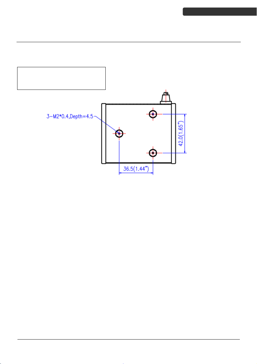
Dimension ............................................................................................................. 9
Programming Guide ............................................................................................ 10
Programming Procedure ................................................................................. 11
Default Parameters ......................................................................................... 12
Scanner Operation .................................................................................. 12
Interface Communication ....................................................................... 12
Symbologies ............................................................................................ 13
Data Formating ....................................................................................... 14
Trigger Command Format ....................................................................... 15
Parameter Setting ........................................................................................... 16
Scanner Operation .................................................................................. 16
Interface Configuration ........................................................................... 25
The Symbologies ..................................................................................... 33
Data Editing............................................................................................. 56
Appendix 1: USB Virtual COM Driver Installation ................................... 59
Appendix 2: Barcode Length Setting ....................................................... 60
Appendix 3: Full ASCII Code 39 Table...................................................... 61


USER’S MANUAL
Advanced Middle-Range CCD Scan Module
1
Instruction
With an easy-to-integrate design and an outstanding scanning performance, this
middle-range CCD scan module is especially made for embedded scanning solution. Its
powerful linear CCD array enables 330 scans per second with a minimum resolution of
4mil for fast scans.
The scan module offers multiple interfaces including keyboard, RS-232C, and HID USB.
Besides, it has three mounting holes on the back of the case reserved for quick and
easy installation into your equipment. When working in field, its two-color LED in the
front gives immediate scanning response and the programmable tone and beep time
are to meet users’ need and enhance productivity.
The module has a newly designed CCD scan engine with light beam bright and clear as
laser beam that gives user best visual indication and its powerful high resolution CCD
acts in remarkable performance.
Maintaining the Scanner
The scanner is designed for long-term trouble-free operation and rarely requires any
maintenance. Only an occasional cleaning of the scanner window is necessary in order
to remove dirt and fingerprints.
Wipe the scan window with a soft lint-free cloth and a non-abrasive cleaner to avoid
scratching and damaging the scan window. The scan window may be cleaned while the
scanner is running.
Scratching the scanner window can reduce the scanning
performance. It is suggested to either recess the window into
the housing or apply a hard-coat on window.

USER’S MANUAL
Advanced Middle-Range CCD Scan Module 2
Overview
Components
Description Function
Exit Window CCD aperture
Interface Cable Used to connect to the host
Good Read LED Indicates a successful reading
Mounting Holes For mounting the device

USER’S MANUAL
Advanced Middle-Range CCD Scan Module
3
Mounting
The scanner is designed to be easily embed into any space limited devices, and it has 3
screwed mounting holes reserved at the bottom.
- Screw description: M2 * 0.4
- Depth = 4.5mm
- Screw quantity: 3 pieces
Figure 1: Screw Position
To ensure the scanner reaches its best performance, the following points need to be
noticed when mounting the scanner:
(a) Do not place the scanner under direct sunlight or any other bright light source
illuminating.
(b) When placing the barcode label, one must be careful not to over tilt, skew and/or
pitch the barcode
(c) Do not place the device at specula reflection position. The LED light of the scanner
reflects directly back on the scanner if it is placed at specula reflection position. As to
the nature of CCD sensor, it will not be able to read any barcodes.
(d) The barcode label must be placed within the effective depth of field (D.O.F.) since it
is the effective reading distance for the barcode from the scanner. For the best
placing position, please refer to the Decode Depth of Field drawing (Figure 2).

USER’S MANUAL
Advanced Middle-Range CCD Scan Module 4
Blink Mode
After the scanner has been inactive for a period of time, the light beam would
automatically start blinking. To stop the scanner from blinking, simply present an
object close to the scanner window. The Blink Mode feature is included to reduce
power consumption and to extend scanner life.
Scan Zone
Different quality and density of a barcode could effect the decode depth
of field. Usually when a barcode has poor printing quality or high
density, the depth of field would be shorter. It is highly suggested not
place the barcode label at the extremes of depth of field as it is often
easy to move out from the reading range.
Figure 2: Scan Zone

USER’S MANUAL
Advanced Middle-Range CCD Scan Module
5
Connection
The scan module has 3 different kinds of interface connection to suit customer’s desire;
the standard cable is black, straight and 2m (6.5 feet) in length. Below shows the
connector types and pin out configuration for each interface.
Keyboard Wedge connection for K/PS2 compatible terminal
PIN-OUT CONFIGURATION
MINI DIN (M) MINI DIN(F)
DIN FUNATION DIN FUNATION
1 PC Data 1 KB Data
2 N.C. 2 N.C.
3 GND 3 GND
4+5V4+5V
5 PC Clock 5 KB Clock
K TYPE MINI DIN(M)+ MINI DIN(F)
6 N.C. 6 N.C.
RS-232C interface uses detachable cable
Please select a suitable cable from the following options
PIN-OUT CONFIGURATION
2. TX 7. CTS
3. RX 8. RTS
DTE Pin-Out
5. GND 9 +5V Input
PIN-OUT CONFIGURATION
2. RX 7. RTS
3. RX 8. CTS
DCE Pin-Out
5. GND 9 +5V Input

USER’S MANUAL
Advanced Middle-Range CCD Scan Module 6
J1 FUNCTION COLOR
#1 RTS Grass
#5 CTS Blue
#4 GND Orange
#3 +5V Red
#5 TX Purple
#1 RX Pink
RS-232 Interface with 2 Housing Connector
TRIGGER WHITE
USB Interface with Type A detachable cable
USB TYPE A
CONNECTOR FUNCTION
1. VCC
2. D-
3. D+
USB TYPE A
4. VSS

Advanced Middle-Range CCD Scan Module
7
USER’S MANUAL
Technical Specification
Power Requirement
Input Voltage
Power Consumption
Operating Current
5V ±10% VDC
0.6 watts
120 mA
Operational
Light Source
Optical System
Depth of Field
Width of Field
Scan Rate
Minimum Bar Width
Print Contrast
Indicators (LED)
Beeper Operation
System Interface
617nm visible LED
Linear CCD array
280 mm
(UPC/EAN 100%, PCS=90%)
180 mm @ 200 mm of depth
330 scans per second
0.1 mm (0.07 mm actually); (Code 39,
PCS=90%)
30% @ UPC/EAN 100%
Two-color LED (green & red)
Programmable tone & beep time
Keyboard, RS-232C, HID USB, Virtual COM
USB
Environment
Operating Temperature
Storage Temperature
Humidity
Ambient Light Immunity
Drop Durability
0℃~ 55℃(32℉~ 131℉)
-20℃~ 60℃(-4℉~ 140℉)
20% to 95% (non-condensing)
Max. 100,000 Lux
Designed to withstand 1.0 m drops
Physical Dimension
Height
Width
Depth
Weight
Mounting
30.25 mm (1.19”)
65.0 mm (2.56”)
80.0 mm (3.15”)
150 g
3-M2 * 0.4 screw hole
Regulatory
EMC
CE & FCC DOC compliance, VCCI, BSMI

Advanced Middle-Range CCD Scan Module 8
USER’S MANUAL
Technical Specification (Continued)
Decode Symbology UPC/JAN/EAN, UPC A & E, EAN-8, EAN-13,
ISBN/ISSN, Code 39, Codabar, Code 128,
EAN 128, Code 93, Interleave 2 of 5,
Addendum 2 or 5, IATA Code, MSI/Plessy,
Chinese Postal Code, Code 32 (Italian
Pharmacode), Industrial 2 of 5, Standard 2
of 5, Matrix 2 of 5 (JAP), Code 11, GS1
DataBar, Telepen

USER’S MANUAL
Advanced Middle-Range CCD Scan Module
9
Dimension

Advanced Middle-Range CCD Scan Module 10
USER’S MANUAL
Programming Guide
Scanning a series of programming bar code labels can configure the scanner. This
allows decoding options and interface protocols to be tailored to a specific application.
The configuration is stored in non-volatile memory and will not be lost by removing
power from the scanner.
The scanner must be properly powered before programming. For RS-232C type
scanners, an external power adapter might be necessary to supply DC power to the
scanner.
During the programming mode, the scanner will acknowledge a good and valid reading
with a short beep. It will give long beeps for either an invalid or bad reading.
See the Default Parameter section for all the programmable parameters. The default
settings will be restored whenever the “Reset” programming label is scanned.

USER’S MANUAL
Advanced Middle-Range CCD Scan Module
11
Programming Procedure
Below is the programming procedure by using barcodes in this guide.
1. Power up the scanner.
2. Scan the Start of Configuration barcode.
3. Scan the barcode for the desired feature. Multiple features can be
enabled/disabled before scanning the End of Configuration barcode.
4. Scan the End of Configuration barcode and save the new configuration.
5. To give up a configuration change, power off the scanner before scanning the
End of Configuration barcode or scan the Abort barcode.
6. For some parameter setting, such as barcode length and identifier code, it is
required to scan the Set barcode to save the configuration.
Default values are highlighted in gray background.
Discard the configuration
Power up the scanner
Scan barcode of the
desired feature
Finish the configuration
Power off the scanner
Scan the “Abort” barcodeScan the “End of
Configuration” barcode
Scan the “Start of
Configuration” barcode

Advanced Middle-Range CCD Scan Module 12
USER’S MANUAL
Default Parameters
This table gives the default settings of all the programmable parameters. The default
settings would be restored whenever the scanner reads the "Reset" programming label
in programming mode. If you wish to change any setting, scan the appropriate
barcodes below.
Scanner Operation
Parameter Default
Same code delay 500msec
Scan mode Auto scan
Beeping frequency Medium
Beeping duration 50ms
LED/Beep before data transmission On
Blink mode timer 500ms
Power save Off
Header and trailer None
Inter message delay None
Inter character delay None
Interface Communication
Parameter Default
RS-232 Interface
Baud rate 9600
Parity None
Data Bits 8
Stop Bit 1
RTS/CTS Off
Terminator <CR><LF>
Keyboard Wedge Interface
Terminal Type PC/AT
Keyboard US keyboard
Terminator Enter
USB Interface
Terminator type Enter
Code mode Scan code
Keyboard US keyboard
Wand Emulation
Wand emulation speed Normal
Data output Black=high

Advanced Middle-Range CCD Scan Module
13
USER’S MANUAL
Symbologies
Parameter Default
Decoder Selection
EAN/UPC Enable
Code 39 Enable
Code 32 Disable
Codabar Enable
ITF 2 of 5 Enable
MSI Disable
Chinese Post Code Disable
Code 93 Enable
Code 128 Enable
EAN-128 Disable
Telepen Disable
Code 11 Disable
Standard 2 of 5 Disable
Industrial 2 of 5 Disable
Matrix 2 of 5 Disable
GS1 DataBar Disable
Code Identifiers
Identifier code as factory standard Disable
Identifier code as AIM standard Disable
Code 39 identifier code M
ITF 2 of 5 identifier code I
Chinese post code identifier code H
UPC-A identifier code A
UPC-E identifier code E
EAN-13 identifier code F
EAN-8 identifier code FF
Codabar identifier code N
Code 128 identifier code K
Code 93 identifier code L
MSI identifier code P
Code 11 identifier code O
Standard 2 of 5 identifier code S
Industrial 2 of 5 identifier code D
Matrix 2 of 5 identifier code G
GS1 DataBar identifier code RS
GS1 DataBar Limited identifier code RL

Advanced Middle-Range CCD Scan Module 14
USER’S MANUAL
GS1 DataBar Expanded identifier code RX
Barcode Length
maximum 32
Codabar
Code 11
Standard 2 of 5
Industrial 2 of 5
Matrix 2 of 5
minimum 6
maximum 62
Code 39
Code 93
Code 128 minimum 3
maximum 16
Chinese Post Code minimum 10
maximum 32
MSI
ITF 2 of 5 minimum 4
maximum 14GS1 DataBar
GS1 DataBar Limited minimum 14
maximum 48
GS1 DataBar Expanded minimum 6
Data Formating
Code Message Format
EAN-13 D1 D2 D3 D4 D5 D6 D7 D8 D9 D10 D11 D12 D13
EAN-8 D1 D2 D3 D4 D5 D6 D7 D8
UPC-A D1 D2 D3 D4 D5 D6 D7 D8 D9 D10 D11 D12
UPC-E D1 D2 D3 D4 D5 D6 D7 D8
Code 128 D1-Dx (default 3~62)
EAN-128 C1 D1-Dx (default 3~62)
Code 39 D1-Dx (default 3~62)
Codabar D1-Dx (default 6~32)
ITF 2 of 5 D1-Dx (default 6~32)
Chinese Post Code D1-Dx (default 8~32)
Code 93 D1-Dx (default 3~32)
MSI D1-Dx (default 6~32)
Other manuals for Z-5160
1
Table of contents
Other Zebex Barcode Reader manuals

Zebex
Zebex ZB-2200AM SERIES User manual

Zebex
Zebex z3190BT User manual

Zebex
Zebex Z-2130 User manual

Zebex
Zebex Z-3272 Plus User manual

Zebex
Zebex z-3101 Operating instructions

Zebex
Zebex Z-3392BT User manual

Zebex
Zebex Z-3051BT User manual

Zebex
Zebex Z-6181 User manual

Zebex
Zebex Z-3191BT Instruction Manual

Zebex
Zebex Z-6170 User manual

Zebex
Zebex Z-6082 User manual

Zebex
Zebex Z-5130 User manual

Zebex
Zebex Z-3100 User manual

Zebex
Zebex Z-5252 User manual

Zebex
Zebex Barcode scanner User manual

Zebex
Zebex Z-900XBT User manual

Zebex
Zebex Z-6070 Series User manual

Zebex
Zebex Z-3052 User manual

Zebex
Zebex z3190BT User manual

Zebex
Zebex Z-8072 User manual