ZENEC ZE-NC2011D User manual

MOUNTING INSTRUCTIONS VW
ZE-N C 2 0 11D

MOUNTING INSTRUCTIONS VW
Anschlussvorbreitung
Verbinden Sie den entsprechenden
Stecker des Hauptanschlusskabels mit
dem CAN/Stalk Interface).
Das Hauptanschlusskabel wird, wie
im Anschlussdiagramm aufgelistet,
angeschlossen.
Dabei sollten Sie darauf achten, dass
der im Hauptanschlusskabel integrierte
8-polige Stecker entsprechend mit dem
ZE-NC2011D verbunden wird.
Connection preparation
Connect the appropriate connector
of the main connection cable with the
CAN/Stalk interface.
Connect the main connection cable as
described in the electrical connections
overview.
Take care to connect the 8-pin
connector, which is integrated in the
main connection cable, to the
Z E - N C 2011 D.
BITTE BEACHTEN PLEASE NOTE
UKW Antennenkabel mit Doppel-Fakra
Anschluss
Je nach Fahrzeugtype ist der UKW
Antennenstecker als gewinkelte Type
ausgeführt. Das ZE-NC2011D lässt sich in
so einem Fall nicht montieren. Es wird ein
Doppelfakra Verlängerungskabel benötigt
(im Handel gesondert erhältlich).
FM antenna cable with double Fakra
connector
Depending on the vehicle model the
FM double Fakra can be an angled
type, which prevents mounting of the
ZE-NC2011D. In such cases, a double
Fakra extension lead is required (to be
purchased separately).

Bevor Sie sich an den Ausbau
des VW Originalgerätes machen,
bereiten Sie das ZE-NC2011D für
den Anschluss vor. Verbinden
Sie das Hauptanschlusskabel
im Lieferumfang wie im
Anschlussdiagramm zu sehen mit
dem ZE-NC2011D. Verbinden Sie
nun den verbleibenden Stecker des
Hauptanschlusskabels mit dem
CAN/Stalk Interface.
Before you approach the removal
of the OE factory installed device,
start by preparing the ZE-NC2011D
for mounting as follows: Connect
the main harness of the set content
to the ZE-NC2011D as shown in the
wiring diagram. Proceed to connect
the appropriate cable end of the
main harness to the CAN/Stalk
interface.
1
M o n t a g e : Installation:
22Hebeln Sie von rechts beginnend
vorsichtig den das Radio
umgebenden Plastikrahmen aus
seiner gesteckten Verankerung.
Für diesen Schritt benötigen Sie
ein entsprechendes Werkzeug
zur Entfernung von Kunststoff-
Paneelen.
Remove the OE unit: Gently lift the
trim frame starting on the right
side of OE device, using a plastic
panel removal tool. For successful
completion of this step, using an
appropriate tool is mandatory.
4Lösen und entfernen Sie die
vier Torx-Schrauben vom VW
Originalgerät.
Unscrew and remove the four Torx
screws of the original VW radio.
1
3Fahren Sie einmal gegen
den Uhrzeigersinn mit dem
Lösewerkzeug um den Rahmen.
Der Zierrahmen sollte sich nun
vollständig von der Konsole ablösen
lassen.
Run the tool anticlockwise to
release the whole trim frame
from the console. The trim frame
should detach from the console
completely.
3
4
55Ziehen Sie das VW Originalgerät
langsam und vorsichtig dem
Schacht. Stecken Sie alle Kabel
an der Gerätrückseite ab. Legen
Sie das Gerät zur Seite um es vor
Beschädigungen zu schützen.
Ziehen Sie die Kabel aus dem
Konsolenschacht, für die nun
folgenden Arbeiten.
Remove the original VW radio unit
by pulling it out of the mounting
slot. Detach all the cables from the
backside of the OE device. Put the
unit aside in a safe place, to protect it
from damage.
Pull the cables out of the console,
so they are within reach for device
connections to be attempted.

Montieren Sie jetzt die GPS
Antenne an geeigneter Stelle
(freie Sicht nach oben) und
ziehen Sie das Antennenkabel in
den Schacht. Montieren sie das
externe Bluetooth Mikrofon, falls
erwünscht. Die beste Position ist
hinter dem Rückspiegel, bzw. hinter
dem Steuerrad.
Install the GPS antenna in a
suitable location underneath the
front window (unobstructed view
up to the sky). Proceed with routing
the antenna cable to the mounting
slot. Mount the external Bluetooth
microphone, if so desired. Ideal
places are behind the rear mirror or
behind the steering wheel.
6
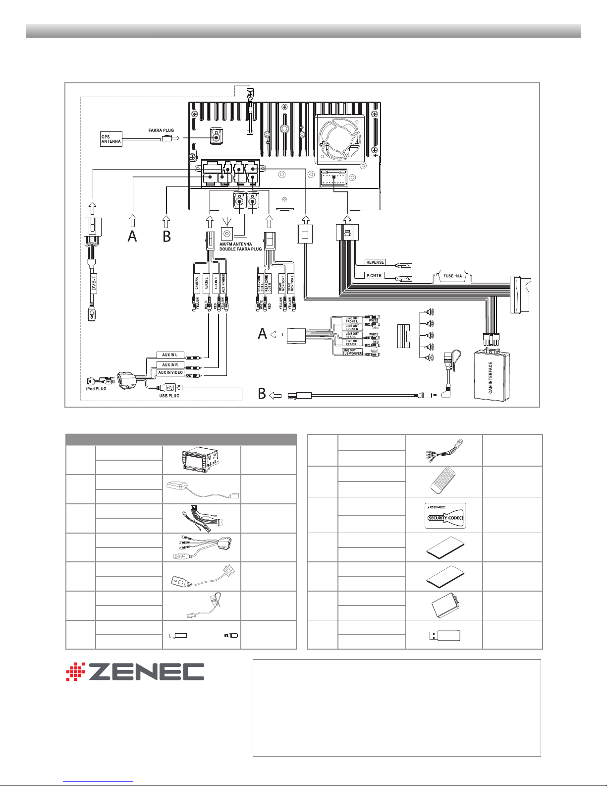
77Stecken Sie den Quadlockstecker
vom vorbereiteten ZE-NC2011D Gerät
an das Gegenstück im Fahrzeug an
und schliessen Sie die Verriegelung.
Verbinden Sie die den Fakrastecker
vom GPS Antennenkabel mit dem
Gerät und auch das Kabel vom
externen Mikro, wenn dieses
montiert wurde.
Bevor das ZE-NC2011D in den
Schacht geschoben wird, stecken sie
den Doppelfakra Antennenstecker
vom Fahrzeug am Gerät an.
Insert the Quadlock plug of the
ZE-NC2011D into the receptor of
the vehicle and lock it. Connect
the Fakra plug of the GPS antenna
cable on the backside of the
device - and do the same with the
plug of the external microphone, if
the external mic has been fitted.
Before you can insert the
ZE-NC2011D into the slot, you must
connect the FM antenna dual Fakra
plug to the respective connector of
the device.
9Drücken Sie die Zierblende wieder
auf. Der Einbau ist hiermit beendet.
Press the trim frame back on.
The installation is completed.
6
8Verstauen Sie die Kabel in den
Randbereichen und schieben
Sie das ZE-NC2011D in den
Schacht. Vermeiden Sie zuviel
mechanischen Druck auf die Front.
Es könnten Stecker abbrechen
oder Kabel gequetscht werden.
Schrauben Sie das ZE-NC2011D
mit den vier Originalschrauben
wieder fest.
Lay the wires to the side, making
room for the device. Carefully slide
the ZE-NC2011D into the bay. Avoid
applying too much mechanical
pressure to prevent shearing of
wires and broken connectors.
Fix the the ZE-NC2011D in place,
using the four original Torx screws.
8
9
bl
bl Nach beendetem Einbau starten
Sie den Motor und fahren aus der
Garage ins Freie (GPS Antenne
braucht „freie Sicht nach oben“).
Das ZE-NC2011D schaltet sich mit
der Zündung ein – wechseln Sie
nun manuell in den Navigations-
modus durch drücken der NAV
taste und lassen Sie das Gerät ca.
3 - 5 Minuten lang den „Sat Fix“
erstellen.
Solange das Gerät noch Satelliten
sucht, wird dies über ein Icon mit
kreisenden Punkten auf dem Bild-
schirm dargestellt.
Sie können nun das Gerät
ausschalten, ein Navigationsziel
eingeben oder aber weitere
Einstellungen im Setup Menü nach
persönlichem Wunsch vornehmen.
With the installation completed, start
the engine and drive your vehicle
out of the garage into open terrain
(GPS antenna must have free “sight
up to the sky”). The ZE-NC2011 will
turn on with the ignition – please
select the navigation mode manually
by pressing the NAV button. Device
now needs 3 to 5 minutes to create
“Sat Fix”.
As long as the device is searching for
GPS satellites, you can see a small
icon with rotating dots on the screen.
You can turn your device off, enter
a destination or continue to set
functions according to personal
preferences in the setup menu.

➜ Das Fahrzeug ist mit einem Eigendiagnosegerät (DME)
ausgestattet.
Um Fehlermeldungen zu vermeiden, muss vor
Montagebeginn unbedingt der negative Pol der
Fahrzeugbatterie abgehängt werden.
➜ Eine einwandfreie Funktion des ZE-NC2011D kann nur
dann gewährleistet werden, wenn Sie das im Lieferumfang
enthaltene Zubehör verwenden.
➜ Es ist nicht nötig, am originalen Anschlusskabel
Veränderungen irgendwelcher Art vorzunehmen.
➜ Achten Sie bei der Installation darauf, dass die
verschiedenen Anschlusskabel und Zubehörteile nicht
durch scharfe Kanten beschädigt und die Anschlusskabel
nicht geknickt werden.
➜ Je nach Präferenz und Wahl des geräteinternen oder
des externen (zu montierenden) Mikrofons, muss im
„Setup Menü“ die Mikrofonquelle für den Bluetooth
Modus entsprechend angepasst werden.
➜ Achten Sie vor der finalen Montage des ZE-NC2011D
darauf, dass alle Steckverbindungen auf der Geräte-
rückseite richtig verbunden und fest eingerastet sind.
➜ Bei Fragen oder Problemen wenden Sie sich an
Ihren ZENEC-Händler, bei dem Sie das Gerät gekauft
haben. Zusätzlich finden Sie unter www.zenec.com eine
ausführliche FAQ Datenbank, wo viele der Fragen und
Probleme, welche während der Installation auftreten
könnten, entsprechend beantwortet werden.
➜ Da Updates (Software und Kartenmaterial) für
das Navigationssystem nur über den USB-Anschluss
installiert werden können und sich der USB-
Anschluss an der Rückseite des ZE-NC2011D befindet,
sollten Sie die im Lieferumfang befindliche Media
Link Box unbedingt an einem leicht zugänglichen Ort
installieren. Die Media Link Box verfügt über einen
entsprechenden USB Port.
Bitte Beachten/Please Note
➜ Tampering with the on-board electrical system might
cause error codes to be stored in the DME.
It is thus recommended to disconnect the GND wire of the
negative battery pole before you start with any installation
work.
➜ The flawless function of the ZE-NC2011D can only
be guaranteed, when the original accessories and wire
harnesses contained in the set are deployed as described in
this installation manual.
➜ The ZE-NC2011D is a plug and play product,
modifications on the original wire loom of the vehicle are
not required at all.
➜ When mounting the ZE-NC2011D always pay proper
attention not to damage any of the wires, plugs or other
parts. Avoid applying too much mechanical force especially
when pushing the unit back into the slot.
➜ Depending on the preference and selection of the
device internal or external (to be installed) microphone,
the BT microphone source must be checked and chosen
accordingly, in the setup menu.
➜ Please check if all plug-and-socket connections on the
rear of the ZE-NC2011D are properly seated before you lock
the unit in place.
➜ Please contact your authorized ZENEC dealer or the
distributor of the country, where you have purchased your
E>GO unit, if you have any technical problems or further
questions.
In addition, you can look up a detailed FAQ data base on
www.zenec.com, where most of the questions revolving
around the connectivity or the installation of a given E>GO
model are explained in detail.
➜ Any update of the main unit software or the
navigation system (software and map data) requires
the USB port of the media link box to be present and
accessible. For this purpose, the installation of the
media link box is mandatory. The media link box is
contained in the ZE-NC2011D set – just make sure you
find a good and suitable mounting location that is easy
to access (i.e. glove compartment, arm rest box etc.).

Anschlussdiagramm/Electrical Connections Overview Diagram
ZENEC by ACR AG
Bohrturmweg 1
CH-5330 Bad Zurzach
Schweiz/Switzerland
E-Mail: [email protected]
www.zenec.com
Firma/Company:
Druckfehler und technische Änderungen vorbehalten. Subject to technical changes and misprints.
Stand Juli 2012 · Rev.B
TOUCH ANOTHER WORLD
Packliste/Packing list
NO. ITEM SKETCH MAP QUANTITY
1
Grundgerät
1
Main unit
2
Externe GPS-Antenne
1
External GPS antenna
3
Hauptanschlusskabel
1
Main wire harness
4
Media Link Box
1
Media link box
5
DVB-T Anschlusskabel
1
DVB-T connection
cable
6
Externes
BT Mikrofon 1
External
BT microphone
7
BT Mikrofon
Adapterkabel 1
BT microphone
interface
8
Steckbares
Anschlusskabel 3
Detachable cable
9
Fernbedienung
2
Remote control
10
Diebstahlschutz-
aufkleber
1
Anti-theft label
11
Bedienungsanleitung
3
User manual
12
Montageanleitung
1
Mounting instructions
13
CAN Bus Interface
1
CAN bus interface
14
USB-Stick
1
USB stick
Table of contents
Other ZENEC Car Video System manuals

ZENEC
ZENEC ZE-NC5011D User manual

ZENEC
ZENEC E GO ZE-NC3152 User manual

ZENEC
ZENEC Z-E3726 Instruction manual

ZENEC
ZENEC Z-E3756 Technical manual

ZENEC
ZENEC Z-E2026 User manual

ZENEC
ZENEC Z-E3766 User guide

ZENEC
ZENEC ZE-MR902-DVD User manual

ZENEC
ZENEC Z-E2014M User manual

ZENEC
ZENEC ZE-NC5010 User manual

ZENEC
ZENEC ZE-NC510 Mounting instructions

ZENEC
ZENEC Z-E2050 User manual

ZENEC
ZENEC Z-E2055 User manual

ZENEC
ZENEC ZEM-W600DDMM User manual

ZENEC
ZENEC ZE-NC3131D User manual

ZENEC
ZENEC Z-E3776 User guide

ZENEC
ZENEC ZE-NC510 User manual

ZENEC
ZENEC ZE-MC5600 - BT COMPATIBILITY LIST V1.9 User manual

ZENEC
ZENEC INFOTAINER Z-N328 User manual

ZENEC
ZENEC Z-E2060 User manual

ZENEC
ZENEC ZE-NC514 User manual