manuals.online logo
Brands
  1. Home
  2. •
  3. Brands
  4. •
  5. ZKTeco
  6. •
  7. Security System
  8. •
  9. ZKTeco RF100 User manual

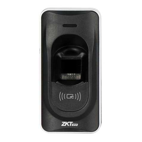
ZKTeco RF100 User manual

-
+
-
+
DC12V
+
+
-
-
+
DC12V
GND
+12V
-
+
DC12V
+
-
-
+
-
+
+
-
-
+
DC Power
RS485 TCP/IP
① ②
③
④⑤
⑥
-
GND
+12V
AL+
AL-
NC
COM
NO
BUT
GND
SES
BELL+
BELL-
GND
+12V
GND
+12V
AL+
AL-
NC
COM
NO
BUT
GND
SES
BELL+
BELL-
-
+
GND
+12V
AL+
AL-
NC
COM
NO
BUT
GND
SES
BELL+
BELL-
AL+
AL-
NC
COM
NO
BUT
GND
SES
BELL+
BELL-
AL+
AL-
NC
COM
NO
BUT
GND
SES
BELL+
BELL-
Installation Guide for RF100 Device
I. Install device
II. Access control system overview
RS232/RS485
Converter
Card
reader
Release
button
Alarm
Lock Door
sensor
!Warning: Don’t connect wires with power on!
III. Connect to door lock
1)device and lock share power supply
NC lock NO lock
Notice:If lock’s working power is DC12V,
and working current is least 1000mA less
than that of access control device power
supply, wiring with sharing power supply
can be adopted.
Notice: Wiring with lock power supplied
independently is recommended for the
following states:
1) Lock’s working power is DC 12V,
power’s current is device not 1A more
than that of lock.
2)Lock’s standard voltage is not DC12V.
3)The distance between lock and device
is long.
NO lock
NC lock
Ⅳ. Connection with other device
Alarm
Alarm
power
Release
button
Door sensor
2)device and lock don’t share power supply
DC Power
DC Power DC Power
1)Post the mounting template on
the wall. Drill holes according to
the marks on the template.(Holes
for screw and wiring)
3) Take away the screw on
the bottom of device
2)Take off the water-proof cushion
5)Fix the cushion and plate on
the wall
4) Release the mounting plate 6) Fix the device with the plate
after all wiring completed
⑤Access control device can be connected with external out-go
switch, which provides convenience to open door from the inside.
① When a registered person verified, the access control device
will export signal to open the door.
② Door sensor will detect on-off state to sense whether the door
is opened by accident or the door is not closed well, alarm will
③If access control device is torn down illegally, or door sensor
is abnormal, or menace alarm gives off, the device will export
④ Connect a Weigand reader to work as a controller.
⑥Access control software to manage multi devices via RS485
Access control system
alarm signal.
or TCP/IP.
The device could connect to NC or NO locks, the connection terminal is not same, please according to the following
diagram to make connection.
1)The rating output of the alarm no more than DC12V.
The device’s working voltage is DC12V, with
working current 500mA,standby current 50mA .
Make sure the connection as the diagram(Don’t
connect the poles in reverse.).
Ⅴ.Power connection
be given off under abnormal condition.
Notice:
2)The device has no bell button,so BELL+ and BELL-
terminals don’t work temporarily.
+
-
FR 107
+
-
FR 107
+
-
FR 107
+
-
FR 107
8) Equipment needed to connect access control software to register users.
2) alarm for records
1) reset
RF100 can also be used as independent access control device and store record. When the record count is close
to or exceeds the capacity, the machine will give off warning. The default free capacity warning count is 99
records(This value can be set through software).
For example, when the free capacity warning count is 99, the remaining capacity is X:
1) when 0<X≤99, the buzzer will give 4 sounds continually and one sound again;
2)when X≤0, the buzzer will give 5 sounds continually, and the next record will not be saved .
RXD
GND
485A
WD 0
WD 1
GND
DATA0
DATA1
GND
485B
2、RS485
3、TCP/IP
!
TXD
485A
485B
485A 485B
485A 485B 485A 485B
PC
…
RXD
GND
485A
WD 0
WD 1
GND
485B
TXD
VIII. Device communication
1、RS232
RS485 converter
RS232 bus
RS485 bus
PC
serial port
232T Pin2-Txd
232R Pin3-Rxd
GND Pin5-Gnd
485A
485B
Terminal definition
Terminal number PC serial port Terminal number PC serial port
RS485 communication+
RS485 communication-
Warning: Don’t connect wires with power on!
Mask:255.255.255.0
IP:192.168.1.100 IP:192.168.1.124
Mask:255.255.255.0
1 <—— > 3
2 <—— > 6
3 <—— > 1
6 <—— > 2
Joint 1 Joint 2
Pin Pin
TX+
TX -
RX+
RX -
RX+
RX -
TX+
TX -
Cable order Pin Color Pin Cable order
TX+ <— — > 1
TX -
2 <— —
RX+ <— — > 3
4 <— —
5 <— — > 5
RX - 6 <— —> 6
7 <— — > 7
8 <— —> 8
white-orange
3
1
orange
white-green
blue
white-blue
green
white-brown
brown
>2
>4
TX+
TX -
RX+
RX -
Ⅸ. Other function
Front
Bottom
If wrong operation or other unexpected fault
makes device fail in working normally, use
this function to restart the device.
Ⅹ. Notice
DATA0
DATA1
GND
+12V
IND 0
IND 1
GND
BEEP
GLED
RLED
+12V
GLED
RLED
BEEP
Find a top pointed
tool with diameter
of 2mm.
Ⅵ. Wiegand output connection
Wiegand 26output interface, export the verified user
number or card number to the controller.
Wiegand 26input interface to connect a Wiegand reader, the
device works as a controller to verify the information sent
from the wiegand reader.
Reader and access control can be installed both inside and
outside the door and control the lock and out & in together.
VII. Wiegand input connection
Notice:
1)The distance between device and access controller or card reader shouldn’t be over 90 meters (If longer distance
is needed or there is interference in using environment, please use Wiegand signal delay.).
2)To ensure the stability of the Wiegand signal, the device must share the GND with controller or Wiegand reader.
1)Connection between device to PC via cross cable.
2)Lan connection
Switch
Manual reset
1)Make sure all connection is correct before power on the device or not wiring when the device is powered.
2)DC12V/3A power adaptor is recommended to power the device, You can consult technicians for detailed information.
3)Please read wiring instruction carefully, damage casued by abnormal operation is beyond maintenance guarantee.
5)To prevent machine damage caused by too powerful instant static in winter or in the place where there is much
static, please connect ground wire firstly, then connect other wires.
6)If the distance between power supply and machine is long, please don’t use network cable or other wires.While
selecting wire for power supply, voltage attenuation caused by too long distance transmission should be taken
7)While using RS485 communication method for network deployment, RS485 cable and RS232/485 converter required, bus
structure is recommended. If RS485 communication distance is over 100 meters, add a terminal-matched resistor
Please install the device according to this guide, we are not responsible for such damage caused by any abnormal operation.
account.
(with 120Ω) to RS485 bus.
4)Make sure there is no bare part of the connection terminal.
Other ZKTeco Security System manuals

ZKTeco ProFace X User manual

ZKTeco

ZKTeco ProFace X User manual

ZKTeco FaceDepot-7BL User manual

ZKTeco

ZKTeco FaceDepot-7BL User manual

ZKTeco FMD Pro 2.0 User manual

ZKTeco

ZKTeco FMD Pro 2.0 User manual

ZKTeco OP-400 User manual

ZKTeco

ZKTeco OP-400 User manual

ZKTeco ZKRF10M User manual

ZKTeco

ZKTeco ZKRF10M User manual

ZKTeco SpeedFace Series User manual

ZKTeco

ZKTeco SpeedFace Series User manual

ZKTeco DM10 User manual

ZKTeco

ZKTeco DM10 User manual

ZKTeco FR1200 User manual

ZKTeco

ZKTeco FR1200 User manual

ZKTeco ProBio User manual

ZKTeco

ZKTeco ProBio User manual

ZKTeco SF1008+ User manual

ZKTeco

ZKTeco SF1008+ User manual

ZKTeco ZKX6550 User manual

ZKTeco

ZKTeco ZKX6550 User manual

ZKTeco G4 Pro Series User manual

ZKTeco

ZKTeco G4 Pro Series User manual

ZKTeco FaceKiosk-H13 User manual

ZKTeco

ZKTeco FaceKiosk-H13 User manual

ZKTeco X7 User manual

ZKTeco

ZKTeco X7 User manual

Popular Security System manuals by other brands

Konig SEC-AED10 (V.2) manual

Konig

Konig SEC-AED10 (V.2) manual

Mobit SAT406 instructions

Mobit

Mobit SAT406 instructions

Speco IOMOD user guide

Speco

Speco IOMOD user guide

Sylvania SY14Q6084CN instruction manual

Sylvania

Sylvania SY14Q6084CN instruction manual

Panasonic WV-AS710 operating instructions

Panasonic

Panasonic WV-AS710 operating instructions

Interlogix ACL800SUW-BSMF installation manual

Interlogix

Interlogix ACL800SUW-BSMF installation manual

TeleAlarm TA72 quick guide

TeleAlarm

TeleAlarm TA72 quick guide

Dahua DSS4004 Initialization User's Manual

Dahua

Dahua DSS4004 Initialization User's Manual

Vixen Horns VXS-9075AR installation guide

Vixen Horns

Vixen Horns VXS-9075AR installation guide

Whelen Engineering Company 1010 installation guide

Whelen Engineering Company

Whelen Engineering Company 1010 installation guide

jablotron JA-163A manual

jablotron

jablotron JA-163A manual

SVAT CV501 - 16CH instruction manual

SVAT

SVAT CV501 - 16CH instruction manual

Pivot PA-SK1 QUICK INFO

Pivot

Pivot PA-SK1 QUICK INFO

Honeywell Home PROSiXSIREN Quick installation guide

Honeywell Home

Honeywell Home PROSiXSIREN Quick installation guide

Bosch PR111B Reference manual

Bosch

Bosch PR111B Reference manual

MOOSE Z900 user manual

MOOSE

MOOSE Z900 user manual

Permaconn DAS Reliance 128 Programming manual

Permaconn

Permaconn DAS Reliance 128 Programming manual

Fortinet FortiAnalyzer-800 quick start guide

Fortinet

Fortinet FortiAnalyzer-800 quick start guide

manuals.online logo
manuals.online logoBrands
  • About & Mission
  • Contact us
  • Privacy Policy
  • Terms and Conditions

Copyright 2025 Manuals.Online. All Rights Reserved.