ZKTeco ZKRF10M User manual

1D Barcode Scanner User Manual
Page | 1 Copyright©2020 ZKTECO CO., LTD. All rights reserved.
Thank you for choosing our product. Please read the instructions carefully
before operation. Follow these instructions to ensure that the product is
functioning properly. The images shown in this manual are for illustrative
purposes only.
For further details, please visit our Company’s website
www.zkteco.com.
User Manual
ZKRF10M&ZKRF20M
Date: October 2022
Doc Version: 1.0
English

ZKRF10M&ZKRF20M User Manual
Page | 2 Copyright©2022 ZKTECO CO., LTD. All rights reserved.
Copyright © 2022 ZKTECO CO., LTD. All rights reserved.
Without the prior written consent of ZKTeco, no portion of this manual can be copied or forwarded in any
way or form. All parts of this manual belong to ZKTeco and its subsidiaries (hereinafter the "Company" or
"ZKTeco").
Trademark
is a registered trademark of ZKTeco. Other trademarks involved in this manual are owned by
their respective owners.
Disclaimer
This manual contains information on the operation and maintenance of the ZKTeco equipment. The
copyright in all the documents, drawings, etc. in relation to the ZKTeco supplied equipment vests in and is
the property of ZKTeco. The contents hereof should not be used or shared by the receiver with any third
party without express written permission of ZKTeco.
The contents of this manual must be read as a whole before starting the operation and maintenance of the
supplied equipment. If any of the content(s) of the manual seems unclear or incomplete, please contact
ZKTeco before starting the operation and maintenance of the said equipment.
It is an essential pre-requisite for the satisfactory operation and maintenance that the operating and
maintenance personnel are fully familiar with the design and that the said personnel have received
thorough training in operating and maintaining the machine/unit/equipment. It is further essential for the
safe operation of the machine/unit/equipment that personnel has read, understood and followed the
safety instructions contained in the manual.
In case of any conflict between terms and conditions of this manual and the contract specifications,
drawings, instruction sheets or any other contract-related documents, the contract conditions/documents
shall prevail. The contract specific conditions/documents shall apply in priority.
ZKTeco offers no warranty, guarantee or representation regarding the completeness of any information
contained in this manual or any of the amendments made thereto. ZKTeco does not extend the warranty
of any kind, including, without limitation, any warranty of design, merchantability or fitness for a particular
purpose.
ZKTeco does not assume responsibility for any errors or omissions in the information or documents which
are referenced by or linked to this manual. The entire risk as to the results and performance obtained from
using the information is assumed by the user.
ZKTeco in no event shall be liable to the user or any third party for any incidental, consequential, indirect,
special, or exemplary damages, including, without limitation, loss of business, loss of profits, business
interruption, loss of business information or any pecuniary loss, arising out of, in connection with, or

ZKRF10M&ZKRF20M User Manual
Page | 3 Copyright©2022 ZKTECO CO., LTD. All rights reserved.
relating to the use of the information contained in or referenced by this manual, even if ZKTeco has been
advised of the possibility of such damages.
This manual and the information contained therein may include technical, other inaccuracies or
typographical errors. ZKTeco periodically changes the information herein which will be incorporated into
new additions/amendments to the manual. ZKTeco reserves the right to add, delete, amend or modify the
information contained in the manual from time to time in the form of circulars, letters, notes, etc. for better
operation and safety of the machine/unit/equipment. The said additions or amendments are meant for
improvement /better operations of the machine/unit/equipment and such amendments shall not give any
right to claim any compensation or damages under any circumstances.
ZKTeco shall in no way be responsible (i) in case the machine/unit/equipment malfunctions due to any
non-compliance of the instructions contained in this manual (ii) in case of operation of the
machine/unit/equipment beyond the rate limits (iii) in case of operation of the machine and equipment in
conditions different from the prescribed conditions of the manual.
The product will be updated from time to time without prior notice. The latest operation procedures and
relevant documents are available on http://www.zkteco.com.
If there is any issue related to the product, please contact us.
ZKTeco Headquarters
Address ZKTeco Industrial Park, No. 32, Industrial Road,
Tangxia Town, Dongguan, China.
Phone +86 769 - 82109991
Fax +86 755 - 89602394
For business related queries, please write to us at: sales@zkteco.com.
To know more about our global branches, visit www.zkteco.com.

ZKRF10M&ZKRF20M User Manual
Page | 4 Copyright©2022 ZKTECO CO., LTD. All rights reserved.
About the Company
ZKTeco is one of the world’s largest manufacturer of RFID and Biometric (Fingerprint, Facial, Finger-vein)
readers. Product offerings include Access Control readers and panels, Near & Far-range Facial Recognition
Cameras, Elevator/Floor access controllers, Turnstiles, License Plate Recognition (LPR) gate controllers and
Consumer products including battery-operated fingerprint and face-reader door locks. Our security
solutions are multi-lingual and localized in over 18 different languages. At the ZKTeco state-of-the-art
700,000 square foot ISO9001-certified manufacturing facility, we control manufacturing, product design,
component assembly, and logistics/shipping, all under one roof.
The founders of ZKTeco have been determined for independent research and development of biometric
verification procedures and the productization of biometric verification SDK, which was initially widely
applied in PC security and identity authentication fields. With the continuous enhancement of the
development and plenty of market applications, the team has gradually constructed an identity
authentication ecosystem and smart security ecosystem, which are based on biometric verification
techniques. With years of experience in the industrialization of biometric verifications, ZKTeco was
officially established in 2007 and now has been one of the globally leading enterprises in the biometric
verification industry owning various patents and being selected as the National High-tech Enterprise for 6
consecutive years. Its products are protected by intellectual property rights.
About the Manual
This manual introduces the operations of ZKRF10M&ZKRF20M.
All figures displayed are for illustration purposes only. Figures in this manual may not be exactly consistent
with the actual products.

ZKRF10M&ZKRF20M User Manual
Page | 5 Copyright©2022 ZKTECO CO., LTD. All rights reserved.
TABLE OF CONTENTS
1OVERVIEW............................................................................................................................................ 6
INTRODUCTION................................................................................................................................................................................................6
APPEARANCE...................................................................................................................................................................................................6
1.2.1 DETECTOR......................................................................................................................................................................................................... 6
1.2.2 ELECTRONIC TAG............................................................................................................................................................................................7
1.2.3 DEACTIVATOR AND DETACHER..................................................................................................................................................................7
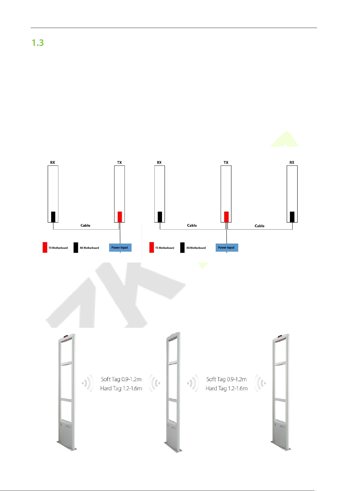
SYSTEM INTRODUCTION .................................................................................................................................................................................8
1.3.1 WORKING MODE............................................................................................................................................................................................. 8
1.3.2 TAG DETECTION DISTANCE .........................................................................................................................................................................8
PRODUCT SPECIFICATIONS.............................................................................................................................................................................9
2PERFORMANCE AND TECHNICAL FEATURES................................................................................... 10
FEATURES.......................................................................................................................................................................................................10
ZKRF10M MOTHERBOARD INTRODUCTION .............................................................................................................................................10
2.2.1 TX MOTHERBOARD ..................................................................................................................................................................................... 10
2.2.2 RX MOTHERBOARD ..................................................................................................................................................................................... 11
ZKRF20M MOTHERBOARD INTRODUCTION .............................................................................................................................................11
2.3.1 TX MOTHERBOARD ..................................................................................................................................................................................... 12
2.3.2 RX MOTHERBOARD ..................................................................................................................................................................................... 13
3DEACTIVATOR AND DETACHER........................................................................................................ 14
DEACTIVATOR................................................................................................................................................................................................14
3.1.1 INSTRUCTION................................................................................................................................................................................................ 14
3.1.2 POWER SUPPLY ............................................................................................................................................................................................ 14
3.1.3 INSTALLATION PREPARATION ................................................................................................................................................................. 14
3.1.4 DEACTIVATOR AND SOFT TAG ................................................................................................................................................................ 14
3.1.5 POWER CONNECTION ................................................................................................................................................................................ 14
3.1.6 THE DEACTIVATOR USES........................................................................................................................................................................... 15
3.1.7 THE SOUND ADJUSTMENT FUNCTION.................................................................................................................................................. 15
3.1.8 PRECAUTIONS FOR THE USE OF DEACTIVATOR................................................................................................................................. 15
3.1.9 PRECAUTIONS FOR THE USE OF SOFT TAGS ....................................................................................................................................... 15
DETACHER .....................................................................................................................................................................................................16
3.2.1 INSTRUCTION................................................................................................................................................................................................ 16
3.2.2 PRECAUTIONS FOR THE USE OF THE DETACHER............................................................................................................................... 16
4INSTALLATION SETUP ....................................................................................................................... 17
PREPARATION BEFORE INSTALLATION .........................................................................................................................................................17
PRODUCT INSTALLATION INSTRUCTIONS ....................................................................................................................................................17
4.2.1 SINGLE DETECTION CHANNEL WORKING MODE............................................................................................................................... 17
4.2.2 DUAL DETECTION CHANNEL OPERATING MODE .............................................................................................................................. 18
4.2.3 MULTI-DETECTION CHANNEL OPERATING MODE............................................................................................................................. 18
5MAINTENANCE AND CLEANING ....................................................................................................... 20
SIMPLE TROUBLESHOOTING.........................................................................................................................................................................20
SYSTEM IS NOT WORKING PROPERLY ..........................................................................................................................................................20
SYSTEM DETECTION SENSITIVITY IS REDUCED ............................................................................................................................................20
SYSTEM DOES NOT ALARM...........................................................................................................................................................................21
SYSTEM ERROR ALARM.................................................................................................................................................................................21

ZKRF10M&ZKRF20M User Manual
Page | 6 Copyright©2022 ZKTECO CO., LTD. All rights reserved.
1Overview
Introduction
EAS (Electronic Article Surveillance) system, also known as Electronic Article Theft Prevention System, is
one of the commodity security measures widely used in the large-scale retail industry. EAS system is
mainly composed of three parts: detector, deactivator and electronic tag. Antenna is installed in the exit of
store. Tag contain a tiny electronic circuit. When the tag appears in the detection range, antenna gives an
alarm. Therefore, when customers enter the store, it is easier for you to make eye contact with them and
provide a good shopping experience.
Appearance
1.2.1 Detector
ZKRF10M ZKRF20M

ZKRF10M&ZKRF20M User Manual
Page | 7 Copyright©2022 ZKTECO CO., LTD. All rights reserved.
1.2.2 Electronic Tag
There are electronic tags with different appearances to choose from.
1.2.3 Deactivator and Detacher

ZKRF10M&ZKRF20M User Manual
Page | 8 Copyright©2022 ZKTECO CO., LTD. All rights reserved.
System Introduction
The EAS RF series products have a basic design that allows them to adapt to a wider range of application
scenarios. Simultaneously, an aluminum alloy design is used to make sure that the structure is stable and
can withstand long-term use. A TX unit can support up to two RX units. More product combinations allow
for more cost-effective solutions to a wide range of application scenarios.
1.3.1 Working Mode
Here are two common ways to use the product. That are single-channel mode (one TX and one RX) and
dual-channel mode (one TX and two RX).
1.3.2 Tag Detection Distance
The tag's identification distance is generally related to the installation environment, product model, and
tag type of the customer. The tag recognition distances shown below are just only for reference.
Customers must choose the product's installation distance based on the actual use environment.

ZKRF10M&ZKRF20M User Manual
Page | 9 Copyright©2022 ZKTECO CO., LTD. All rights reserved.
Product Specifications
Model ZKRF10M ZKRF20M
Detection Range
0.9m to 1.6m
(Depend on tag)
0.9m to 1.8m
(Depend on tag)
Power AC110 to 220V, 50 to 60hz AC110 to 220V, 50 to 60hz
Rated Power ≤15w ≤15w
Center Frequency 8.2Mhz 8.2Mhz
Working Mode
TX+RX
TX+RX
Dimensions
1580 * 380 * 30(mm)
1570 * 440 * 40(mm)
Dimensions with Packaging
1630 * 440 * 210(mm) 1630 * 520 * 190(mm)
Net Weight 8.5 Kg / ctn 10 Kg / ctn
Weight with Packaging 11.5 Kg / ctn 13.5 Kg / ctn
Packing Unit
2 pcs / ctn
2 pcs / ctn

ZKRF10M&ZKRF20M User Manual
Page | 10 Copyright©2022 ZKTECO CO., LTD. All rights reserved.
2Performance and Technical Features
Features
Cost-effective.
Concise design can be applied to multiple scenarios.
Aluminum alloy material ensures long-lasting durability.
Advanced Digital Signal Processing (DSP) technology.
Suitable for wide entrance solutions.
ZKRF10M Motherboard Introduction
2.2.1 TX Motherboard
No. Port Function
1 Transmit Antenna Transmitting antenna interface.
2
Signal synchronization
Signal synchronization output interface.
3 Power Indicator TX unit power indicator interface.
4 Power Fuse Power fuse (250V 0.5A)
5
Cable Interface
Connect to the RX unit using a cable.

ZKRF10M&ZKRF20M User Manual
Page | 11 Copyright©2022 ZKTECO CO., LTD. All rights reserved.
6 Power Power interface.
7 Ground Wire Ground interface. Make sure that your equipment works safely.
8 Main and secondary
transmit switch
When there are two TX units working in combination, one of them
needs to be used as the main transmitter and the other as the
secondary transmitter.
9 Signal synchronization Signal synchronization input interface.
2.2.2 RX Motherboard
No. Port Function
1
Receive Antenna
Receiving antenna interface.
2 Signal Indicator
When no tag passes by, the signal interference level of the installation
environment is displayed. W
hen there is a tag passing by, the signal
strength of the label is displayed.
3 Power Indicator RX unit power indicator interface.
4 Buzzer Buzzer interface.
5
Alarm Indicator
Alarm indicator interface.
6 Power Fuse Power fuse (250V 0.5A)
7 Ground Wire Ground interface. Make sure your equipment works safely.
8
Cable Interface
Connect to the TX unit using a cable.

ZKRF10M&ZKRF20M User Manual
Page | 12 Copyright©2022 ZKTECO CO., LTD. All rights reserved.
ZKRF20M Motherboard Introduction
2.3.1 TX Motherboard
No.
Port
Function
1
Transmit Antenna
Transmitting antenna interface.
2 Power Fuse Power fuse (250V 0.5A)
3
Cable Interface
Connect to the RX unit using a cable.
4
Power
Power interface.
5 Ground Wire Ground interface. Make sure that your equipment works safely.
6 Signal synchronization Signal synchronization output interface.
7
Signal synchronization
Signal synchronization input interface.
8 Main and secondary
transmit switch
When there are two TX units working in combination, one of them
needs to be used as the main tr
ansmitter and the other as the
secondary transmitter.
9 Power Indicator TX unit power indicator interface.

ZKRF10M&ZKRF20M User Manual
Page | 13 Copyright©2022 ZKTECO CO., LTD. All rights reserved.
2.3.2 RX Motherboard
No. Port Function
1
Receive Antenna
Receiving antenna interface.
2 Power Fuse Power fuse (250V 0.5A)
3 Cable Interface Connect to the TX unit using a cable.
4
Ground Wire
Ground interface. Make sure that your equipment works safely.
5 Signal Indicator
When no tag passes by, the signal interference level of the installation
environment is displayed; when there is a tag passing by, the signal strength
of the label is displayed.
6 Alarm Indicator Alarm indicator interface.
7
Sound Adjustment
Knob
Adjust the volume of the device alarm sound. Turn it clockwise to make the
sound louder.
8
Power Indicator
RX unit power indicator interface.

ZKRF10M&ZKRF20M User Manual
Page | 14 Copyright©2022 ZKTECO CO., LTD. All rights reserved.
3Deactivator and Detacher
Deactivator
3.1.1 Instruction
The RF(Radio Frequency) deactivator is an accessory product of the 8.2MHz RF detection system. Used to
decode soft tags. It consists of 18V DC power adapter and decoder board. The green light on the decoding
board represents the working indicator, which is always on in the standby state, and the red light is on and
the buzzer sounds when decoding. Try to place the item as close to the center of the deactivator panel as
possible while decoding, and try back and forth a few times until the buzzer does not sound. The
deactivator works together with the 8.2MHz RF detection system, and is generally installed on the cashier
to decode the protected goods.
3.1.2 Power Supply
Input Power
18V 1A(DC)
Power Insurance
250V 1A
Decoding Height
maximum 15cm (soft tag)
Maximum Current
150mA (when decoding)
Quiescent Current
not more than 110mA
3.1.3 Installation Preparation
Choose the installation location; the hole's dimensions are 205mm*215cm.
Connect the power adapter and the decoder (pay close attention to observe whether the adapter is
compatible with the power grid in the area).
3.1.4 Deactivator and Soft Tag
3.1.5 Power Connection
Plug and play, no setup required.

ZKRF10M&ZKRF20M User Manual
Page | 15 Copyright©2022 ZKTECO CO., LTD. All rights reserved.
3.1.6 The Deactivator Uses
The deactivator has hard tag recognition. When an undecoded soft tag is used to enter the decoding area
of the deactivator, the buzzer will send out Di-Di-Di (three short beeps), and the decoding is successful. If
the hard tag enters the decoding area, the buzzer will beep (long tone) and give an alarm.
3.1.7 The Sound Adjustment Function
As shown in Figure, adjust and change the volume of the sound. Turn clockwise to make the sound louder,
and turn it counterclockwise to reduce the sound.
3.1.8 Precautions for the Use of Deactivator
Do not put liquids or soluble solids directly on the surface of the deactivator. And it should be wrapped to
prevent liquids from invading the deactivator and burning the circuit board.
3.1.9 Precautions for the Use of Soft Tags
There are three main factors that cause the soft tag to fail to alarm normally: metal shielding, human
shielding and wrong use of tags. Therefore, the following details should be paid attention to in the use of
soft tags:
To protect the product, the soft tag must be attached to it.
The soft tag's placement must be based on the principle of not damaging the product. Soft tags
cannot be attached to leather or other materials due to their high stickiness.
Do not press hard on the soft tag, as this will cause the tag to fail.
Soft tags cannot be directly attached to metal products, tin foil-wrapped products, etc. Metal will
directly shield the soft tag signal, resulting in no alarm.
The tag cannot be used on the human body, nor can it be used on meat packaging, such as ham
sausage, frozen meat, etc. The flesh and the human body will directly shield the soft tag signal,
resulting in no alarm. At the same time, the electrostatic effect of the human body will also cause the
soft tag to fail directly.
Soft tags cannot be attached to plastic bottles or glass bottles with liquids because most liquids
contain trace metal particles, that will block the signals of soft tags. At the same time, the process of
attaching the soft tag to the bottle will cause the tag to bend, which will also make the alarm
impossible.

ZKRF10M&ZKRF20M User Manual
Page | 16 Copyright©2022 ZKTECO CO., LTD. All rights reserved.
The soft tag's sticking position must be flat, and the sticking curve must be as small as possible. It is not
possible to fold it for usage. If the tag is bent too much, the frequency will change but no alert will
sound.
Soft tags cannot be overlapped (more than two) and placed. The whole roll or the whole box cannot
be used for the alarm, and it needs to be used in a single sheet, otherwise it is invalid.
Detacher
3.2.1 Instruction
The detacher can facilitate your use of hard tags.
Tag 1
1. Put lanyard through the item.
2. Align the nails to tag holes.
3. Put the hard tag on the detacher as shown in the picture. Hard tag removed.
Tag 2
1. Put the hard tag on the unlocked area of the detacher as shown in the picture. Press the button to
unlock.
2. Rotate against the direction of the arrow or manually pull to open the hard tag.
3. According to the size of the item, adjust the tag. Rotate the lock in the direction of the arrow. Press the
button, and it will lock with an audible prompt.
3.2.2 Precautions for the Use of the Detacher
1. Don’t fall, or the magnet will lose its magnetism when broken.
2. Do not put bank cards and mobile phones close to this product, it will cause degaussing of bank cards
and damage to mobile phones.

ZKRF10M&ZKRF20M User Manual
Page | 17 Copyright©2022 ZKTECO CO., LTD. All rights reserved.
4Installation Setup
Preparation before Installation
1. Before fixing the EAS product, it is necessary to test the environment of the installation location. When
installing the device, the distance should be as far away as possible from the following environments:
walls full of antennas, high-voltage lines, spotlights, large-area metal objects, etc.
2. After the device is powered on, place it in the desired location.
3. Observe the status of the signal indicator on the receiving motherboard. If any of the indicators here
are off, it means that the working environment is very good and can be installed.
4. It takes about 30 minutes to test the working status of different labels in this working environment.
5. After determining the installation location and installation distance, install the product securely.
Product Installation Instructions
4.2.1 Single Detection Channel Working Mode
Here is a single-detection channel operating mode consisting of a transmitting unit and a receiving unit.
ZKRF10M Installation Diagram

ZKRF10M&ZKRF20M User Manual
Page | 18 Copyright©2022 ZKTECO CO., LTD. All rights reserved.
ZKRF20M Installation Diagram
4.2.2 Dual Detection Channel Operating Mode
Here is a dual-detection channel operating mode consisting of one transmitting unit and two receiving
units.
ZKRF10M Installation Diagram
ZKRF20M Installation Diagram
4.2.3 Multi-detection Channel Operating Mode
You can use different numbers of transmit and receive units to form more detection channels to work to
meet the needs of an ultra-wide entrance and exit scenario.
One thing that must be noted is that if there are 2 or more transmitting units working at the same time
and the installation position is within 10m, you must connect them using a signal synchronization cable.

ZKRF10M&ZKRF20M User Manual
Page | 19 Copyright©2022 ZKTECO CO., LTD. All rights reserved.
This will allow all devices to work properly. Then select one of them as the main signal transmission unit
and the other as the secondary transmission unit.
ZKRF10M Installation Diagram
Here is the operating mode of the ZKRF10M, consisting of two transmitting units and three receiving units.
This will have 4 detection channels that will solve the use case of 4m to 5m wide entrances.
ZKRF20M Installation Diagram
Here is the ZKRF20M, the operating mode consisting of three transmitting units and three receiving units.
This will have 5 detection channels and will solve the use case of a 5m to 6m wide entrance.

ZKRF10M&ZKRF20M User Manual
Page | 20 Copyright©2022 ZKTECO CO., LTD. All rights reserved.
5Maintenance and Cleaning
Simple Troubleshooting
Under normal use conditions, radio frequency detectors generally can work stably for a long period of time,
and system failures caused by component failures are less. Most of the faults are due to:
Improper use.
Poor electrical outlet contact.
Excessive AC voltage fluctuations.
Loose connection cable connections.
Interference from surrounding electrical equipment and certain radio waves.
Interference caused by wires, coils.
Metal frames to equipment.
Carefully analyze the cause of the failure and then eliminate it one by one. Before the cause of the fault is
not found, the settings and parameters of the system cannot be arbitrarily changed. Since all the indicators
of the equipment are adjusted at the factory, they are in a better state.
System is not Working Properly
When each system is not working properly, such as the detection of reduced sensitivity, no alarm or
frequent false alarms, etc., generally the following steps should be checked:
1. Check power
When it is found that the system is not working properly, first check whether the system power is
normal:
1) Whether the power indicator on the board is on;
2) Whether the printed board fuse (f1) is intact;
3) Whether the input power voltage is correct (24vac);
4) Whether the power wiring is open or short circuited.
5) Whether the external power adapter is working properly;
6) Whether the power socket contacts are reliable;
7) Whether the input ac voltage fluctuates too much, etc.
2. After troubleshooting the power supply, you can continue to check other system faults.
System Detection Sensitivity is Reduced
Under normal circumstances, due to the failure of components and components, the detection sensitivity
of the system is reduced. Most of these types of failures are caused by interference between systems and
interference, and the detection of interference caused by metal objects or electrical equipment near the
antenna. For the detection of metal objects, electrical equipment, etc. near the antenna should take
measures to remove, and try to keep it away from the detection antenna system.
This manual suits for next models
1
Table of contents
Other ZKTeco Security System manuals

ZKTeco
ZKTeco X7 User manual

ZKTeco
ZKTeco ZKX6550 User manual

ZKTeco
ZKTeco G4 Pro Series User manual

ZKTeco
ZKTeco ProBio User manual

ZKTeco
ZKTeco FaceDepot-7BL User manual

ZKTeco
ZKTeco FaceKiosk-H13 User manual

ZKTeco
ZKTeco ProFace X User manual

ZKTeco
ZKTeco DM10 User manual

ZKTeco
ZKTeco FMD Pro 2.0 User manual

ZKTeco
ZKTeco OP-400 User manual