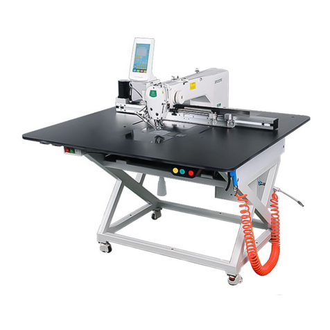
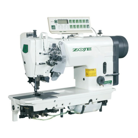
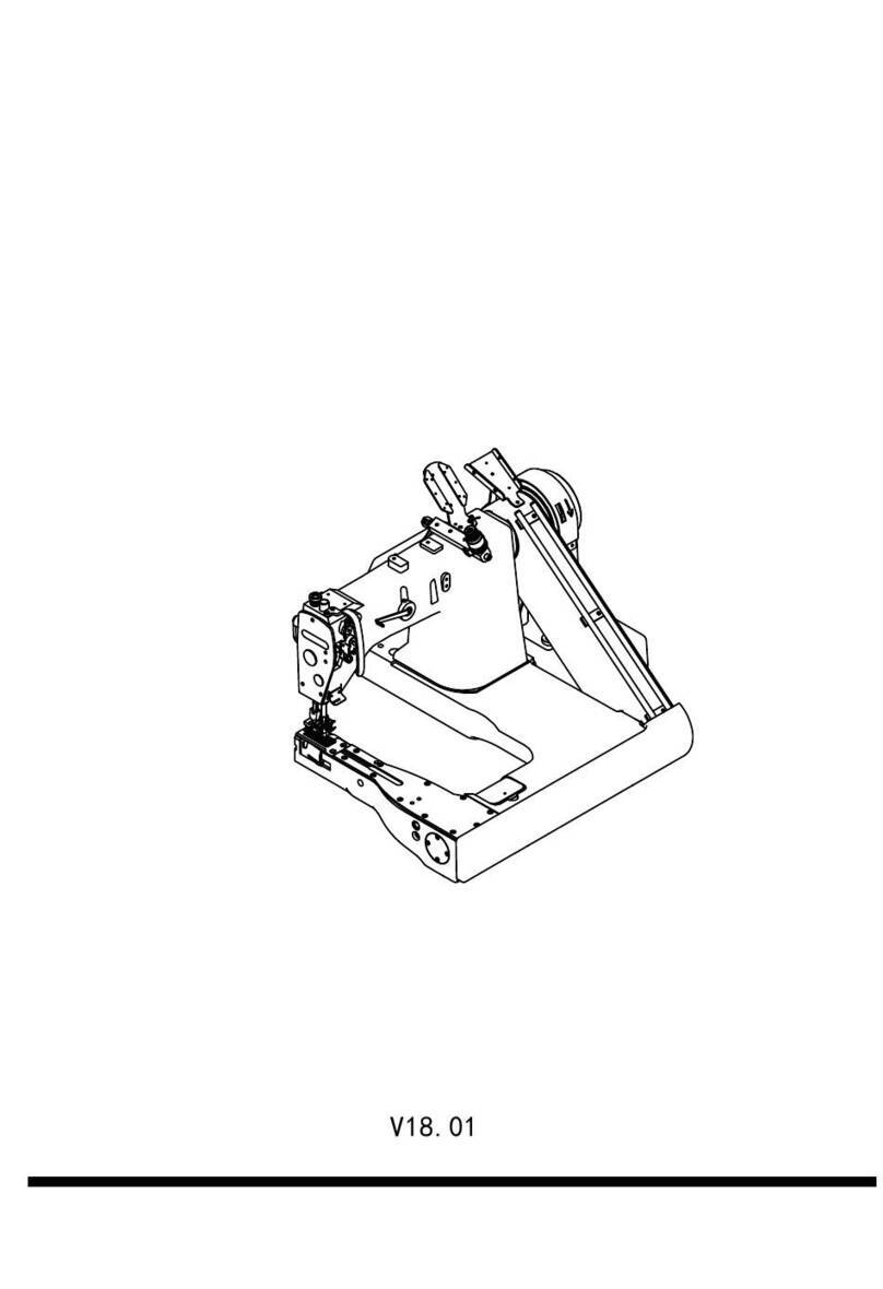
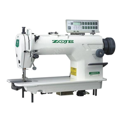
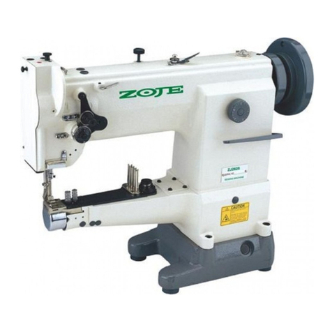
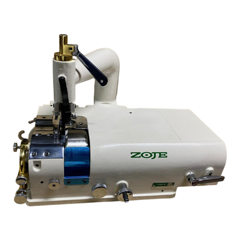
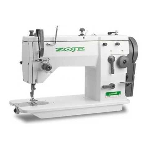
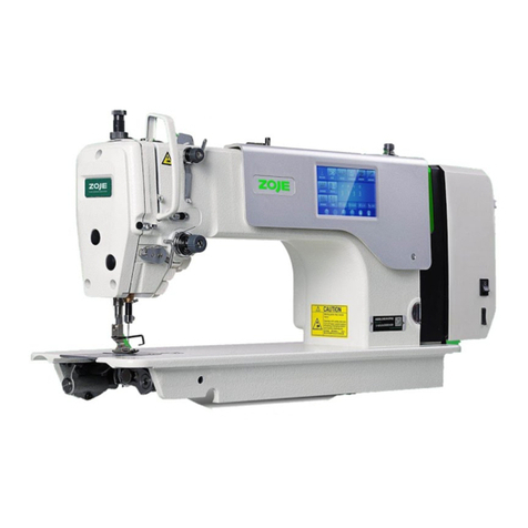
ZOJE 9610 User manual


1. ;
. ;2 2016 01
. !"#$%;3
Notes for using this
operation manual and parts book
1 This book is applicable to sewing machines which have the same plate.
.number as shown on the cover of this book
. .2 This book was prepared based on information available in January 2016
.3 Parts ares subject to changes in design without prior notice.

………………………………………………………… -
…………………………………………………………………………… 1 - 11
1.01 …………………………………………………………………1 - 1
1.02 ………………………………………………………1 - 1
1.03 ………………………………………………………………………1 - 2
…………………………………………………………………… 2 - 12
………………………………………………………………………3 - 13
3.01 96 0,96 0 ………………………………………………………………………3 - 11 2
3.02 …………………………………………………………………………3 - 2
3.03 ………………………………………………………3 - 2
…………………………………………………………………… 4 - 14
………………………………………………………………………5 - 15
5.01 (-D3) ………………………………………5 - 1
5.02 ……………………………………………5 - 1
5.03 ……………………………………………………………………………5 - 2
5.04 …………………………………………………………………5 - 2
5.05 …………………………………………………………………………5 - 2
5.06 ……………………………………………………………5 - 3
5.07 ……………………………………………………………5 - 3
……………………………………………………………………6 - 16
6.01 ……………………………………………………………………………6 - 1
6.01.01 ………………………………………………………………6 - 1
6.02 ………………………………………………………………………6 - 2
6. ………………………………………………………………… 6 - 203
6.0 ……………………………………………………………………………6 -4 3
6.0 …………………………………………………………………6 -5 3
6.0 ……………………………………………………………6 -6 4
6.0 ………………………………………………………………………6 -7 4
………………………………………………………………………7 - 17
7.01 …………………………………………………………7 - 19610
7.02 9620 ………………………………………………………7 - 2
7.03 ;…………………………………………7 - 3
7.04 / ……………………………………………………………………7 - 4

7.05 梭壳穿线/调节梭心线的张力 …………………………………………… 7 - 4
7.06 在9610机型上穿针线并调节针线张力 …………………………………7 - 5
7.07 在9620机型上穿针线并调节针线张力 ……………………………………7 - 6
7.08 设置线迹长度 ………………………………………………………………7 - 7
8 维护与保养 ………………………………………………………………… 8 - 1
8.01 检查/调节空气压力………………………………………………………… 8 - 1
8.02 清洁空气滤清器/润滑器的过滤网 …………………………………………8 - 2
8.03 清洁……………………………………………………………………………8 - 2
8.04 给旋梭加油……………………………………………………………………8 - 3
8.05 旋梭润滑油盒…………………………………………………………………8 - 4
8.06 给线润滑系统的油盒加油……………………………………………………8 - 4
8.07 给伞齿轮副润滑………………………………………………………………8 - 5
9 调整……………………………………………………………………………9 - 1
9.01 对调整工作的提示……………………………………………………………9 - 1
9.02 工具、量规和其它辅助材料…………………………………………………9 - 1
9.03 调整基础机器…………………………………………………………………9 - 2
9.03.01 在9610机型上从缝纫方向上看机针的位置……………………………………9 - 2
9.03.02 在 9620机型上从缝纫方向看机针的位置…………………………………9 - 3
9.03.03 初步调整针的高度……………………………………………………………9 - 4
9.03.04 在 9620机型上针的上升,旋梭到针的距离,针的高度和护针器…………9 - 5
9.03.05 在9610S和9610机型上针的上升,旋梭到针的距离,针的高度和 .
护针器…………………………………………………………………………9 - 7
9.03.06 在 9620机型上从垂直于缝纫方向看机针的位置 ………………………9 - 9
9.03.07 在 9610机型上从垂直于缝纫方向看机针的位置……………………… 9 - 10
9.03.08 开梭器的高度和行程 ………………………………………………………9 - 11
9.03.09 在 9620机型上进给轮高度的调整 ………………………………………9 - 12
9.03.10 在 9610机型上进给轮高度的调整 ………………………………………9 - 13
9.03.11 线迹长度控制的偏心度调整 ………………………………………………9 - 14
9.03.12 线迹长度刻度盘调整 ………………………………………………………9 - 15
9.03.13 杆状曲柄到进给轮的传动调整 ……………………………………………9 - 16
9.03.14 杆状曲柄到滚轮压脚的传动调整 …………………………………………9 - 17
9.03.15 滚轮压脚和进给轮之间的距离 ……………………………………………9 - 18
9.03.16 滚轮压脚调整 ………………………………………………………………9 - 19
9.03.17 按线迹长度刻度盘的指示值调整线迹长度 ………………………………9 - 20
9.03.18 滚轮压脚和进给轮的同步调整 ……………………………………………9 - 21
9.03.19 压料器(仅9620机型才有)……………………………………………………9 - 22
9.03.20 膝提杆 ………………………………………………………………………9 - 23
9.03.21 针线松线调整 ………………………………………………………………9 - 24
9.03.22 挑线簧调整(9610S、9625和9610机型) ……………………………………9 - 25
9.03.23 挑线簧调整(9620机型) …………………………………………………… 9 - 26
9.03.24 绕线器 ………………………………………………………………………9 - 28
目 录

9.03.2 …………………………………………………………9 -5 29
9.03.2 …………………………………………………………………………… 9 -6 30
9.03. ……………………………………………………………… 9 -27 31
9.04 -D …………………………………………………………… 9 - 32
9.04.01 /………………………… 9 - 32
9.04.02 ………………………………………………………… 9 - 33
9.04.03 …………………………………………………… 9 - 34
9.04.04 …………………………………………………………… 9 - 35
9.04.05 ……………………………………………………… 9 - 36
9.04.06 …………………………………………………………… 9 - 37
9.04.07 ……………………………………………………………… 9 - 38
9.04.08 ………………………………………………………………… 9 - 39
9.04.09 ( 9620) ……………………………………………… 9 - 40
9.05 -D3 ………………………………………………………… 9 - 41
9.05.01 ( 9610) …………………………… 9 - 41
9.05.02 ………………………………………… 9 - 42
9.05.03 ( 9620) ………………………… 9 - 43
9.05.04 ( 9620) ……………………………………… 9 - 44
9.05.05 (96 9610) ………………… 9 - 410S 5
9.05.06 (96 9610)………………………………… 9 -10S 46
9 05 07 9610SA 9610A 9 47. . ( )……………………………… -

Contexts Chapter - Page……………………………………………………………………………
1 Safety …………………………………………………………………………
1.01 Safety symbols ………………………………………………………………
1.02 Important points for the user……………………………………………………
1.03 Danger …………………………………………………………………………
……………………………………………………………………2 Proper use
…………………………………………………………………3 Specifications
3.01 9610, 9620 ………………………………………………………
3.02 Needles and threads …………………………………………………………
3.03 Possible models and ……………………………………………………………
……………………………………………………4 Explanation of symbols
………………………………………………………………………5 Controls
5.01 Keys on the machine head (only for machines with -D3 ) ……………………
5.02 Bobbin thread monitoring with stitch counting ………………………………
5.03 Pedal ……………………………………………………………………………
5.04 Lever for lifting roller presser …………………………………………………
5.05 Knee lever ………………………………………………………………………
5.06 Key for setting stitch length ……………………………………………………
5.07 Swing out roller presser ………………………………………………………
……………………………………………6 Installation and comminssioning
6.01 Installation………………………………………………………………………
6.01.01 Adusting the table height………………………………………………………
6.02 Fitting the reel stand …………………………………………………………
6.03 …………………………………………………………………Kippsichtigtes
6.04 С ………………………………………………………………ommissioning
6.05 ………………………………………………………………Tilted work base
6.06 ………………………………………………………………Tilted work base
6.07 Mounting the table top …………………………………………………………
……………………………………………………………………7 Preparation
7.01 Inserting needle on model 9610 ………………………………
7.02 Inserting the needle on model 9620 …………………………………………
Index
1 - 1
1 - 1
1 - 1
1 - 2
2 - 1
3 - 1
3 - 1
3 - 2
3 - 2
4 - 1
5 - 1
5 - 1
5 - 1
5 - 2
5 - 2
5 - 2
5 - 3
5 - 3
6 - 1
6 - 1
6 - 1
6 - 2
6 - 2
6 - 3
6 - 3
6 - 4
6 - 4
7 - 1
7 - 1
7 - 2
1 - 1
1 - 1
1 - 1
1 - 2
2 - 1
3 - 1
3 - 1
3 - 2
3 - 2
4 - 1
5 - 1
5 - 1
5 - 1
5 - 2
5 - 2
5 - 2
5 - 3
5 - 3
6 - 1
6 - 1
6 - 1
6 - 2
6 - 2
6 - 3
6 - 3
6 - 4
6 - 4
7 - 1
7 - 1
7 - 2

7.03 Winding the bobbin thread; adjusting the primary thread tension ………………
7.04 Removing/Inserting the bobbin case ……………………………………………
7.05 Threading the bobbin case/Adjusting the bobbin thread tension ………………
7.06 Threading the needle thread and regulating its tension on model 96 01 …………
7.07 Threading the needle thread and regulating its tension on model 9620 …………
7.08 Setting the stitch length …………………………………………………………
8 Care and maintenance …………………………………………………………
8.01 Checking adjusting the air pressure ……………………………………………
8.02 Cleaning the air filter of the air-filter/lubricator…………………………………
8.03 Cleaning …………………………………………………………………………
8.04 Oiling the hook …………………………………………………………………
8.05 Oil bowl for hook lubrication ……………………………………………………
8.06 Filling the oil reservoir of the thread lubrication unit……………………………
8.07 Lubricating the bevel gears………………………………………………………
9 Adjustment ……………………………………………………………………
9.01 Notes on adjustment ……………………………………………………………
9.02 Tools, gauges and other accessories ……………………………………………
9.03 Adjusting the basic machine ……………………………………………………
9.03.01 Needle position in sewing direction on the 9610………………………………
9.03.02 Needle position in sewing direction on the 9620………………………………
9.03.03 Prelininary adjustment of the needle height ……………………………………
9.03.04 Needle rise, hook clearance, needle height and needle guard on the
9620 ………………………………………………………………………………
9.03.05 Needle rise, hook clearance, needle height and needle guard on the
9630 and 9610……………………………………………………………………
9.03.06 Needle position crosswise to sewing direction on the 9620 …………………
9.03.07 Needle position crosswise to sewing direction on the 9610……………………
9.03.08 Height and stroke of the bobbin case opener …………………………………
9.03.09 Height of the feed wheel on the 9620 …………………………………………
9.03.10 Height of the feed wheel on the 9610 and9610S ………………………………
9.03.11 Stitch length control eccentric …………………………………………………
9.03.12 Stitch length scale disk …………………………………………………………
9.03.13 Shaft crank to feed wheel drive ………………………………………………
9.03.14 Shaft crank to roller presser drive………………………………………………
9.03.15 Clearnce between roller presser and feed wheel ………………………………
…………………………………………………………………9.03.16 Roller presser
9.03.17 Stitch length on stitch length scale …………………………………………
9.03.18 Synchronization of roller presser and feed wheel …………………………
Index
7 - 3
7 - 4
7 - 4
7 - 5
7 - 6
7 - 7
8 - 1
8 - 1
8 - 2
8 - 2
8 - 3
8 - 4
8 - 4
8 - 5
9 - 1
9 - 1
9 - 1
9 - 2
9 - 2
9 - 3
9 - 4
9 - 5
9 - 7
9 - 9
9 - 10
9 - 11
9 - 12
9 - 13
9 - 14
9 - 15
9 - 16
9 - 17
9 - 18
9 - 19
9 - 20
9 - 21
7 - 3
7 - 4
7 - 4
7 - 5
7 - 6
7 - 7
8 - 1
8 - 1
8 - 2
8 - 2
8 - 3
8 - 4
8 - 4
8 - 5
9 - 1
9 - 1
9 - 1
9 - 2
9 - 2
9 - 3
9 - 4
9 - 5
9 - 7
9 - 9
9 - 10
9 - 11
9 - 12
9 - 13
9 - 14
9 - 15
9 - 16
9 - 17
9 - 18
9 - 19
9 - 20
9 - 21

9.03.19 Retainer(only on 9620)………………………………………………
9.03.20 Knee lever………………………………………………
9.03.21 Needle thread tension release …………………………………………
9.03.22 Thread check spring (9610) …………………………………………
9.03.23 Thread check springs (9620) …………………………………………
9.03.24 Bobbin winder ……………………………………………………
9.03.25 Pressure of roller presser …………………………………………
9.03.26 Lubrication ………………………………………………………
9.03.27 Re-engage safety coupling …………………………………………
9.04 Adjusting the thread trimmer -D ………………………………………
9.04.01 Resting position of the roller lever/radial position of the control cam …
9.04.02 Position of the thread catcher holder ……………………………
9.04.03 Distance between thread catcher and needle plate …………………
9.04.04 Position of the thread catcher ………………………………………
9.04.05 Knife position and knife pressure ………………………………………
9.04.06 Bobbin thread retaining spring ………………………………………
9.04.07 Manual cutting test ……………………………………………………
9.04.08 Releasing the tension ……………………………………………………
9.04.09 Linkage rod (only for 9620) ……………………………………………
9.05 Adjustment backtacking mechanism-D3…………………………………
9.05.01 Needle in needle hole (only for 9610)…………………………………
9.05.02 Coupling for roller presser drive ………………………………………
9.05.03 Bever gears for feed wheel drive (on the 9620)…………………………
9.05.04 Bevel gear play (on the 9620) ……………………………………………
9.05.05 Bevel gears for feed wheel drive (on the 9610 and 9610 )S ………………
9.05.06 Bevel gear play(on the 9610 and 9610)S ……………………………………
………………………………9.05.07 Bevel gear play(on the 9610 and 962 )SA 0SA
Index
9 - 22
9 - 23
9 - 24
9 - 25
9 - 26
9 - 28
9 - 29
9 - 30
9 - 31
9 - 32
9 - 32
9 - 33
9 - 34
9 - 35
9 - 36
9 - 37
9 - 38
9 - 39
9 - 40
9 - 41
9 - 41
9 - 42
9 - 43
9 - 44
9 - 45
9 - 46
9 - 47
9 - 22
9 - 23
9 - 24
9 - 25
9 - 26
9 - 28
9 - 29
9 - 30
9 - 31
9 - 32
9 - 32
9 - 33
9 - 34
9 - 35
9 - 36
9 - 37
9 - 38
9 - 39
9 - 40
9 - 41
9 - 41
9 - 42
9 - 43
9 - 44
9 - 45
9 - 46
9 - 47

1. Safety
1.01 Safety symbols
1. Safety
1.01 Safety symbols
Safety Safety
Caution
。
,,,
,。
Caution
。
,,,
,。
!Danger!
Points to be observed。
!
Danger of injury for operating and
specialist personnel!
!Danger!
Points to be observed。
!
Danger of injury for operating and
specialist personnel!
Do not operate without finger guard
and safety devices.
Before threading,changing bobbin
and needle, cleaning etcs witch off
main switch.
Do not operate without finger guard
and safety devices.
Before threading,changing bobbin
and needle, cleaning etcs witch off
main switch.
1.02
Important points for the user
1.02
Important points for the user
●, 。
●,。
●
。
●。
●。
● 。,
●This Instruction Manual is a component of the machine and must be
available to the operating personnel at all times.
●The Instruction Manual must be read before operating the machine for
the first time.
●The operating and specialist personnel must to be instructed in the
safeguards of the machine and safe work methods.
I●t is the duty of the user to operate the machine in perfect running order.
●It is the obligation of the user to ensure that none of the safety
mechanisms are removed or deactivated.
●It is the obligation of the user to ensure that only authorized persons
operate and work on the machine.
1-1
!

Safety Safety
1-2
,,1m
、。
A working area of 1 meter is to be kept free both in front of and behind
the machine in operation so that the machine is always easily
accessible.
,!!
Never reach into the sewing area while sewing! Danger of injury by
the needle!
,!
!!
Never leave objects on the table while adjusting the machine settings!
Objects can become trapped or be slung away! Danger of injury!
1
!,,
!
Do not operate the machine without support 1! Danger due to top-
heavy sewing head! Machine can tip over backwords when tilted!
1.03 Danger1.03 Danger
!
1
2
3
4

1-3
Safety Safety
!
!
Switch the machine off before tilting it backwards!
Danger of injury if the machine is started accidentally!
!3
!
Do not operate the machine wihout its take-up-lever guard !3
Danger of injury due to the motion of the take-up lever!
4 ! 4
。
On machines with thread lubricator, only operate the machine with the eye
guard 4 lowered! The eye guard protects the eyes from oil particles4
from the thread lubrication!
!2
!
Do not operate the machine without tilt lock 2!
Danger of crushing between sewing head and table top!
!
!
Switch the machine off before tilting it backwards!
Danger of injury if the machine is started accidentally!
!3
!
Do not operate the machine wihout its take-up-lever guard !3
Danger of injury due to the motion of the take-up lever!
4 ! 4
。
On machines with thread lubricator, only operate the machine with the eye
guard 4 lowered! The eye guard protects the eyes from oil particles4
from the thread lubrication!
!2
!
Do not operate the machine without tilt lock 2!
Danger of crushing between sewing head and table top!
!
1
2
3
4

2-1
Proper use Proper use
2 Proper use2 Proper use
9620 、,、
。
Is a double-needle, high-speed post bed sewing
machine with driven feed wheel and roller presser.
9610 、,、
()。
Is a single needle, high-speed post bed sewing
machine (post to the right of the needle) with driven
feed wheel and roller presser and synchronized needle.
9620 、,、
。
Is a double-needle, high-speed post bed sewing
machine with driven feed wheel and roller presser.
9610 、,、
()。
Is a single needle, high-speed post bed sewing
machine (post to the right of the needle) with driven
feed wheel and roller presser and synchronized needle.
。
The machines are used for sewing lockstitch seams in the leather and
upholstery industries.
。
The machines are used for sewing lockstitch seams in the leather and
upholstery industries.
,!
,!
、、!
,!
,!
、、!
Any use of these machines which is not approved by the manufacturer
shall be considered as improper use! The manufacturer shall not be liable
for any damage arising out of improper use! Proper use shall also be
considered to include compliance with the operation, adjustment, service
and repair measures specified by the manufacturer!
!

3-1
Specifications Specifications
3 Specifications
3.01 9610 , 9620 ▲
3 Specifications
3.01 9610 , 9620 ▲
………………………………… Stitch type 301 ( /lockstitch)
Clearacne under roller presser 7 mm …………………
Clearance width 245 mm ……………………………………………
Clearance height 115 mm ……………………………………………
Post height 180 mm ……………………………………………
Sewing head dimensions !
Length /approx. 615 mm" …………………………………………… #$
Width /approx. 240 mm ……………………………………………… #$
( ) Height (above table) /approx. 500 mm %&' ………………… #$
Bedplate dimensions 518 x 177 mm …………………………………
Max.speed()
9610 3000 / /spm………………………………………………………… * ◆
9620 2000 / /spm………………………………………………………… * ◆
Connection data,
Operating voltage 220 V 10%, 50/60 Hz-./ ………………………… ±
Max.power consumption 1.2 kVA(#0123 ………………………………
Fuse protection 1 x 16 A, /insert456 ………………………………… 78
Noise data9:
-.;<&=>?)-.@A?9:BC
Emission sound level at the work place at appropriate speed
( DIN 45 635-48-A-1, ISO 11204, ISO 3744, ISO4871)9:DEFG
(Noise measurement in accordance with DIN 45 635-48-A-1, ISO
11204, ISO 3744, ISO4871)
9610 2400 / : L 79 dB(A)) * ………………………………… ≤ ■
pA
9610 at a speed of 2400spm L 79 dB(A)…………………………… … ≤ ■pA
9620 1600 / : L 75 dB(A)) * ………………………………… ≤ ■pA
9620- at a speed of 1600spm L 75 dB(A)……………………………… ≤ ■pA
9610 1600 / : L 73 dB(A)) * ………………………………… ≤ ■pA
9610 at a speed of 1600spm L 73 dB(A)…………………………… … ≤ ■pA
Net weight of sewing head /approx. 61 kgJKL ……………………… #$
Gross weight of sewing head /approx. 71 kgJML …………………… #$
Subject to alteration▲ 4NOP?QR
Dependent on material, work◆ STUVW、-Y、Z[\
operation and stitch length
KpA = 2,5 dB
■

3-2
Specifications Specifications
3.02 Needles and threads3.02 Needles and threads
Model
Thread thickness
(Nm) max.
Synthetics
Thread thickness
(Nm) max.
Synthetics
▲Needle
thickness
1/100mm
▲Needle
thickness
1/100mm
9620
Needle system
9620
Needle system
M
H
40/3
15/3 134-35
134134-35
134
▲
or similar strengths of other types of thread▲
▲
or similar strengths of other types of thread▲
Note: materials: M M lightweight
Medium-heavy materialsHH
Note: materials: M M lightweight
Medium-heavy materialsHH
3.03 Possible models and subclasses3.03 Possible models and subclasses
9610,9610S,9610SA,9620,9620S,9620SA
M…………………………………………………
Model For sewing lightweight medium-weightmaterialsM………………………… and
H………………………………………………………………
Model For sewing medium-heavy materialsH………………………………………
Additional equipment
-D·» ……………………………………………………………
Subclass-D Automatic edge trimmer…………………………………………………
D3·» …………………………、、
Subclass-D3 Automatic edge trimmer, automatic presser……………………………
foot lifter, backtacking device.
9610,9610S,9610SA,9620,9620S,9620SA
M…………………………………………………
Model For sewing lightweight medium-weightmaterialsM………………………… and
H………………………………………………………………
Model For sewing medium-heavy materialsH ………………………………………
Additional equipment
-D·» ……………………………………………………………
Subclass-D Automatic edge trimmer…………………………………………………
D3·» …………………………、、
Subclass-D3 Automatic edge trimmer, automatic presser……………………………
foot lifter, backtacking device.
▲ (Nm)
▲
▲ (Nm)
▲
1/100mm
1/100mm
9620
9620
M40/3 134-35 134
H15/3 134-35 134
9610
9610
90 14/
120 14/
90 14/
120 14/
9610
Needle system
9610
Needle system

4-1
4 Explanation of symbols4 Explanation of symbols
Explanation of symbols Explanation of symbols
,
In this Instruction Manual, work to be carried out or important information
is accentuated by symbols which have the following meanings:
,
In this Instruction Manual, work to be carried out or important information
is accentuated by symbols which have the following meanings:
, Note, information
Cleaning, care,
Lubrication
,,,()
Maintenance, repairs, adjustment, service work (only to be carried
out by technical staff)
, Note, information
Cleaning, care,
Lubrication
,,,()
Maintenance, repairs, adjustment, service work (only to be carried
out by technical staff)

5-1
Controls Controls
5 Controls5 Controls
5.01 (-D3)5.01 (-D3)
●, ,1
。
● ,2
。
1●As long as key is pressed during
sewing, the machine sews in reverse
direction.
Keys can be used for parameter●2
settings, Instruction Manual of
Electronic Control.
●, ,1
。
● ,2
。
1●As long as key is pressed during
sewing, the machine sews in reverse
direction.
Keys can be used for parameter
●2
settings, Instruction Manual of
Electronic Control.
Keys on the machine head (only for machines with-D3 9610 )SKeys on the machine head (only for machines with-D3 9610 )S
5.02
Bobbin thread monitoring with stitch counting
5.02
Bobbin thread monitoring with stitch counting
- D3/..
Machines without D3/..
100● ,
1 。
●,
。
100●About stitches before reaching
the preset number of stitches, LED 1
Flashes.
After the thread has been trimmed●
and the bobbin changed, The stitch
counting begins anew.
- D3/..
Machines without D3/..
100● ,
1 。
●,
。
100●About stitches before reaching
the preset number of stitches, LED 1
Flashes.
After the thread has been trimmed●
and the bobbin changed, The stitch
counting begins anew.
,。
Presetting the number of stitches, see Instruction Manual of
Electronic Control.
,。
Presetting the number of stitches, see Instruction Manual of
Electronic Control.

5-2
Controls Controls
0= Neutral position
1= Sewing
2= -D3( 、9610S
......)
Raiser roller presser(on machines with-
D3 ..)
、9610S
3= ( -D..
)
Trim sewing threads (on machines with-D..)
0= Neutral position
1= Sewing
2= -D3( 、9610S
......)
Raiser roller presser(on machines with-
D3 ..)
、9610S
3= ( -D..
)
Trim sewing threads (on machines with-D..)
5.03 Pedal5.03 Pedal
5.04 Lever for lifting roller presser5.04 Lever for lifting roller presser
● 。1
●The roller presser can be raised by
turning lever .1
● 。1
●The roller presser can be raised by
turning lever .1
● ,1
。
●The roller presser can be raised by
pressing the knee lever in the direction1
of the arrow.
● ,1
。
●The roller presser can be raised by
pressing the knee lever in the direction1
of the arrow.
5.05 Knee lever5.05 Knee lever

1
5-3
Controls Controls
5.06
Key for setting stitch length
5.06
Key for setting stitch length
● 1
7.08( “”)。
●The stitch length is set by pressing key 1
and turning the balance wheel (see
).Chapter 7.08 Setting the stitch length
● 1
7.08( “”)。
●The stitch length is set by pressing key 1
and turning the balance wheel (see
).Chapter 7.08 Setting the stitch length
●,
,。
●When the roller presser is raised, it
can be swung out by pulling it lightly
downwards.
●,
,。
●When the roller presser is raised, it
can be swung out by pulling it lightly
downwards.
5.07
Swing out roller presser
5.07
Swing out roller presser

6
Installation and comminssioning
6
Installation and comminssioning
Installation and commissioning Installation and commissioning
!!
!
The machine must only be installed and commissioned by qualified
personnel!
All relevant safety regulations must be strictly adhered to!
!!
!
The machine must only be installed and commissioned by qualified
personnel!
All relevant safety regulations must be strictly adhered to!
,。
,、,
The site where the machine is installed must be provided with suitable
connections for electric current.
It must be ensured that the standing surface of the machine site is
firm and horizontal, and that sufficient lighting is provided for.
,。
For packing and transportation reasons the table top is in the lowered
position. The table height is adjusted as described below.
,。
,、,
The site where the machine is installed must be provided with suitable
connections for electric current.
It must be ensured that the standing surface of the machine site is
firm and horizontal, and that sufficient lighting is provided for.
,。
For packing and transportation reasons the table top is in the lowered
position. The table height is adjusted as described below.
6.01 Installation6.01 Installation
6.01.01
Adusting the table height
6.01.01
Adusting the table height
● ,12
。
● 。1
●,
。2
●Loosen screws and and set the12
table height as required.
Firmly tighten screw .●1
Set the required pedal position and●
tighten screw .2
● ,12
。
● 。1
●,
。2
●Loosen screws and and set the12
table height as required.
Firmly tighten screw .●1
Set the required pedal position and●
tighten screw .2
,
。
。
If the machine is delivered without a table, be sure to use a stand and
table top that can hold the weight of the machine with its motor.
It is very important to ensure that the stand of the machine is firm and
steady, also during sewing.
,
。
。
If the machine is delivered without a table, be sure to use a stand and
table top that can hold the weight of the machine with its motor.
It is very important to ensure that the stand of the machine is firm and
steady, also during sewing.
6-1
!
!

6.02 Fitting the reel stand6.02 Fitting the reel stand
Installation and commissioning Installation and commissioning
● 。
●Fit the reel stand as shown in Fig.
● 。
●Fit the reel stand as shown in Fig.
!
!
6.03 6.03
Maschine ausschalten!
Verletzungsgefahr durch unbeasichtigtes
Anlaufen der Maschine!
Maschine ausschalten!
Verletzungsgefahr durch unbeasichtigtes
Anlaufen der Maschine!
Die im zubehor befindliche kippsicheru-
ng1 mit schraube 2 anschrauben.
Die im zubehor befindliche kippsicheru-
ng1 mit schraube 2 anschrauben.
Maschine nicht ohne kippsicherung 1
betreiben! Sicherung 1 betreilben!
Quetschgefahr zwischen oberteil und
tischplatte!
Maschine nicht ohne kippsicherung 1
betreiben! Sicherung 1 betreilben!
Quetschgefahr zwischen oberteil und
tischplatte!
●
!1
!
!1
!
6-2
()21 ()21
●
2
1
①
①
After installing the Table,plsremove
the suppor screws ①!
This manual suits for next models
1
Table of contents
Other ZOJE Sewing Machine manuals