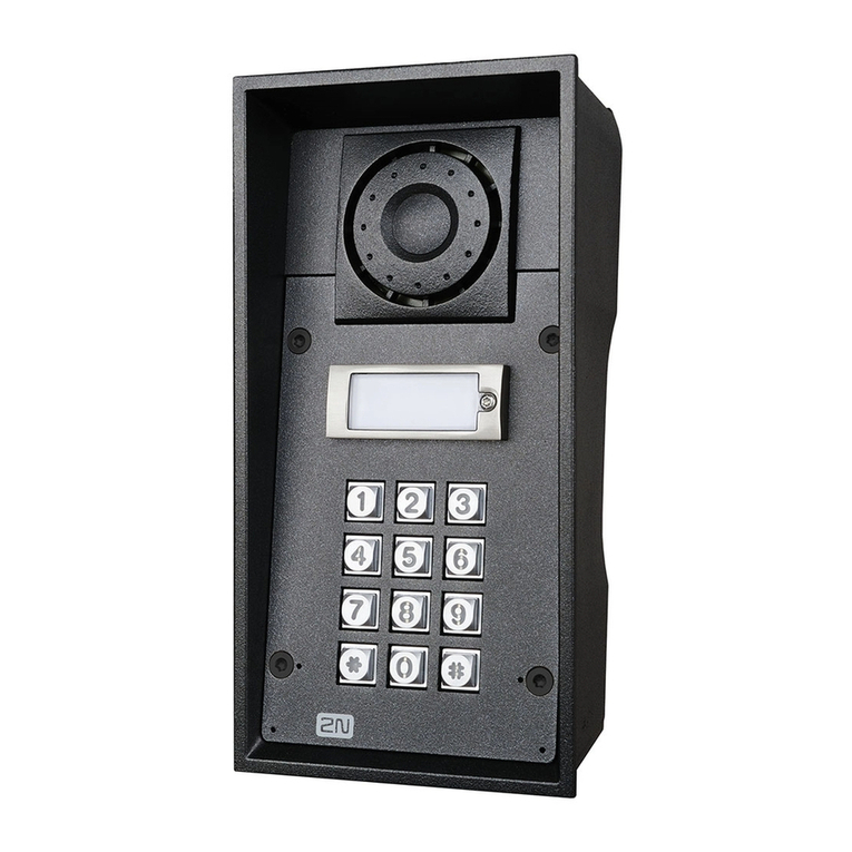
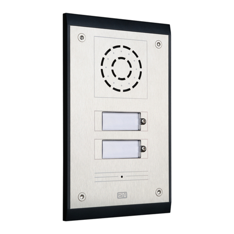
2N Helios IP Operator's manual

Helios IP
Documentation

Helios IP –Documentation Page 2
Content
LIST OF TABLES 3
LIST OF FIGURES 3
DOCUMENT UPDATE HISTORY 4
DEVICE CONNECTION 5
DEVICE CONFIGURATION 5
API ACCESS 5
SIP ACCOUNT SETTING 7
SWITCH SETTINGS 8
DRIVER INFO 9
DRIVER HISTORY 9
HARDWARE COMPONENTS AND VERSIONS 9
HELIOS IP DRIVER CONFIGURATION 10
HELIOS IP BUS CONTROLLER 10
HELIOS IP BUS CONTROLLER SETTINGS 10
SWITCH SETTINGS 10
SUPPORTED HELIOS IP BUS CONTROLLER 11
SUPPORTED SWITCH COMMANDS 11
HELIOS IP INTEGRATION TESTS 12
PREPARATION OF INTEGRATION TESTS 13
NECESSARY COMPONENTS 13
DEVICE TREE CREATION 13
CENTRAL UNIT PREPARATION FOR TESTING 14
CONNECTION 14
BASIC FUNCTION TESTS 15
TCF000A DUPLICATE ADDRESS 15
TCF010A MISSING HW COMPONENT 16
TCF020A PARAMETER VALUE BEYOND RANGE 17
TRE000A CONNECTION LOSS 18
TRE010A COMMUNICATION LOSS 19
TFC010A CONTACT ACTIVATION/DEACTIVATION 20
T001 –CALL SETUP CHECK 21

Helios IP –Documentation Page 3
List of Tables
TABLE 1: DOCUMENT UPDATE HISTORY ................................................................................................................. 4
TABLE 2: DRIVER INFO ............................................................................................................................................ 9
TABLE 3: EVENT LOGGING ...................................................................................................................................... 9
TABLE 4: DRIVER HISTORY ..................................................................................................................................... 9
TABLE 5: HELIOS IP BUS CONTROLLER SETTINGS................................................................................................. 10
TABLE 6: SWITCH SETTINGS IN C4......................................................................................................................... 10
TABLE 7: SUPPORTED HELIOS IP BUS CONTROLLER COMMANDS.......................................................................... 11
TABLE 8: SUPPORTED SWITCH COMMANDS........................................................................................................... 11
TABLE 9: NECESSARY COMPONENTS..................................................................................................................... 13
TABLE 10: C4 REQUISITES..................................................................................................................................... 13
List of Figures
FIGURE 1: HTTP API SETTINGS .............................................................................................................................. 5
FIGURE 2: HTTP API ACCESS SETTINGS ................................................................................................................. 6
FIGURE 3: SIP ACCOUNT SETTING........................................................................................................................... 7
FIGURE 4: SWITCH SETTINGS................................................................................................................................... 8
FIGURE 5: BASIC TESTING DIAGRAM..................................................................................................................... 14
FIGURE 6: BASIC TESTING DIAGRAM..................................................................................................................... 21
Helios IP –Documentation Page 4
Document Update History
Date
Updated by
Changes
01/07/2015
Ondřej Pohl
Document first version
31/07/2015
Ondřej Pohl
Adding of integration tests
03/08/2015
Ondřej Pohl
New driver adaptations
18/09/2015
Armen Hajrapetjan
New driver adaptations
22/10/2015
Armen Hajrapetjan
Bug fix
12/11/2015
Armen Hajrapetjan
Fix default login parameters
Table 1: Document Update History

Helios IP –Documentation Page 5
Device Connection
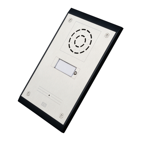
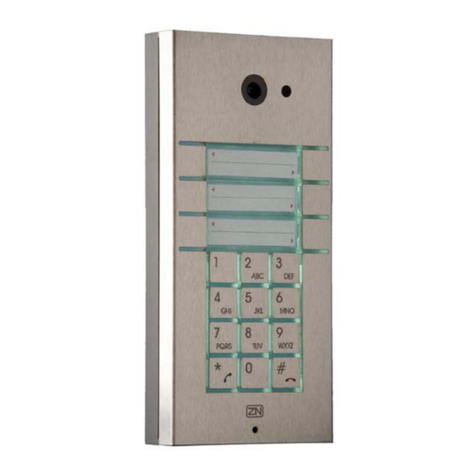
The Helios IP device is connected to the Local Area Network. The intercom is supplied via PoE or an
external power supply.
Device Configuration
API Access
Make basic configuration after connecting the device to the LAN.Default access values are (Login:
admin, Password: 2n). The C4 - Helios IP communication runs via the intercom HTTP API. Set the API
login data and enable the API functions to access this function. Go to the Services menu and select the
HTTP API submenu via the Helios IP web interface. Enable the functions, select the TLS or TCP
connection type and set the authentication type to None or Basic as shown in the figure below.
Figure 1: HTTP API Settings

Helios IP –Documentation Page 6
Now switch the tab to Account 1 and enable the account. The HTTP API login data settings are optional
and need not be completed. Select User rights in the User Settings as shown in the figure below and save
the changes.
Figure 2: HTTP API Access Settings

Helios IP –Documentation Page 7
SIP Account Setting
Set the SIP account in the intercom to enable outgoing calls to a defined phone number. Select
Telephone in the Services menu. Refer to the figure below for an example of functional setting.
Figure 3: SIP Account Setting

Helios IP –Documentation Page 9
Driver Info
Function
Communication reinitialisation, run and stop
Event download from device
Outgoing call to defined number
Outgoing call hang-up
Switch control
Table 2: Driver Info
The driver allows you to log the following events in the device:
Event
Switch state change
Card tapping on card reader
Device state
Audio loop test result
Call state change
Table 3: Event Logging
Driver History
Date
Version
Description
01/07/2015
1.0.1
Driver first version
31/07/2015
1.0.2
Compatibility with integration tests
03/08/2015
1.0.3
Additional test compatibility
18/09/2015
1.0.4
Adjusted for the new API
22/10/2015
1.0.5
Bug fix
12/11/2015
1.0.9
Bug fix
Table 4: Driver History
Hardware Components and Versions
Supported firmware version: 2.13

Helios IP –Documentation Page 10
Helios IP Driver Configuration
Helios IP Bus Controller
Information on Helios IP Bus Controller and switch features and configurable values.
Helios IP Bus Controller Settings
Feature name
Meaning
Default
value
Example of value
Enabled
Driver enable/disable
Yes
Mobile number
Phone number for outgoing calls
550
Password
Helios IP HTTP API access
password
2n
URL
Helios IP address
https://192.168.1.2
Account
Helios IP HTTP API access user
name
admin
Location
Device location
Front door
Table 5: Helios IP Bus Controller Settings
Switch Settings
Feature name
Meaning
Default
value
Example
of value
Digital Output ID
Switch ID [1 - 4] for activation
1
Location
Switch location
Front
door
Video camera
Table 6: Switch Settings in C4
Information on Helios IP Bus Controller and switch commands.

Helios IP –Documentation Page 11
Supported Helios IP Bus Controller
Element
Command
Meaning
Command
Reinitialisation
Reinitialise communication with the device after changes.
Run
Run communication with the device.
Stop
Stop communication with the device.
Close
Close the outgoing call.
Call
Start an outgoing call to a defined number.
Table 7: Supported Helios IP Bus Controller Commands
Just one Helios IP switch can be controlled via the driver.
Supported Switch Commands
Element
Command
Meaning
Delete
Remove a switch from the list.
Command
ON
Activate the selected switch.
OFF
Deactivate the selected switch.
Table 8: Supported Switch Commands

Helios IP –Documentation Page 12
HELIOS IP INTEGRATION TESTS

Helios IP –Documentation Page 13
Preparation of Integration Tests
Necessary Components
The integration tests require the following components:
Component
Count of
components
Device with a web browser and LAN access
1 or more
Helios IP intercom
1
Ethernet cables
4 or more
External power supply for Helios IP if no PoE is available
1
Sip Proxy
1
IP phone
1
Table 9: Necessary Components
The following items are required for Central Unit running, management and configuration:
Item
Count of
items
C4 installation
1
C4 User Manual
1
This documentation
1
Table 10: C4 Requisites
Device Tree Creation
1. Create a bus controller with device URL and Account and Password values set according to the
Helios IP HTTP API login data.
2. Create an output under the bus controller with ID as set for the Helios IP switch.

Helios IP –Documentation Page 14
Central Unit Preparation for Testing
Connection
Connect the Central Unit and Helios IP as shown in the diagram below.
Figure 5: Basic Testing Diagram

Helios IP –Documentation Page 15
Basic Function Tests
TCF000A Duplicated Addresses
The test verifies the presence of a switch with duplicate identifier.
Test Procedure
1. Stop Helios PI using the Stop button.
2. Create two switches in the device.
3. Set identical Digital Output IDs for the two switches.
4. Start the Helios IP driver using the Reinitialisation button.
Expected Results
1. The two switches pass into the ConfigurationFailure status.
2. The driver is not initialised and stops.
3. The following record appears in the log:
At ‘DEVICE1’ and ‘DEVICE2’ nodes of ‘DRIVER’ a duplicate address ‘ADDRVALUE’ was
detected.
Where
DEVICE1 a DEVICE2 represent the names of the duplicate switches.
DRIVER represents the device name.
ADDRVALUE is the switch ID.

Helios IP –Documentation Page 16
TCF010A Missing HW Item
The test verifies the driver in case the device configuration is incomplete. In this case, the driver has to log
the Missing Device event on the nearest superior level of the device configuration tree after every event
receipt.
Note
The test is not supported due to communication protocol limitations.

Helios IP –Documentation Page 17
TCF020A Property Value Out Of Range
The test verifies configuration containing a value beyond the allowed range. The test verifies whether the
driver is able to detect this error at initialisation.
Test Procedure
1. Stop the driver if running.
2. Add a driver with an ID higher than that of Helios IP.
3. Run the device.
Expected Results
1. The driver is not initialised and stops.
2. The driver with a wrong ID passes into the ConfigurationFailure state.
3. The following event is recorded in the log:
Invalid property value ‘VALUE’ on ‘DEVICE’.
Where
VALUE is the wrong ID value.
DEVICE represents the device name.

Helios IP –Documentation Page 18
TRE000A Connection Lost
The test verifies connection loss between the C4 server and the device.
Test Procedure
1. Run the device driver and wait for connection.
2. Disconnect the cable from the router/switch making sure that the Windows still detects
Ethernet connection.
3. Wait for connection loss detection.
4. Reconnect the cable.
5. Wait for communication recovery.
Expected Results
1. The following events are recorded in the log:
Connection lost to 'DEVICE'.
Connection with 'DEVICE' restored. Number of attempts: RETRYCOUNT.
Where
DEVICE represents the device name.

Helios IP –Documentation Page 19
TRE010A Communication Lost
The test verifies the driver if communication gets lost between the LAN module and device -
there is no disconnection on the transport layer.
Note
The test is not supported due to communication protocol limitations.

Helios IP –Documentation Page 20
TFC010A Contact Activation and Deactivation
The test verifies the input/ouput contact control and monitoring.
Test Procedure
1. Click ON on the switch.
2. When the contact is activated, click OFF on the switch.
Expected Results
1. When the switch is activated, its state is marked Open.
2. When the switch is deactivated, its state is marked Normal.
3. The following events are recorded in the log:
Command ‘On’ send to ‘DEVICE’ by ‘PERSON’.
’DEVICE’ opened.
Command ‘Off’ send to ‘DEVICE’ by ‘PERSON’.
’DEVICE’ closed.
Where
DEVICE is the switch name.
PERSON represents the command entering person.
Other manuals for Helios IP
16
Table of contents
Other 2N Intercom System manuals

2N
2N IP Safety User manual

2N
2N IP Solo User manual

2N
2N EntryCom Troubleshooting guide

2N
2N Helios IP Instruction sheet

2N
2N Helios IP Instruction sheet

2N
2N Helios Force User manual

2N
2N Helios Uni User manual

2N
2N IP Video Kit User manual

2N
2N Helios IP Verso User manual

2N
2N Helios IP Automation Instruction sheet