2N Clip User manual

2N® Clip User Manual
v.1.0
www.2n.com

2N® Clip User Manual
2 / 75
•
•
•
•
•
•
•
•
•
•
•
•
•
•
•
•
•
•
•
•
•
•
•
•
•
•
•
•
•
•
Obsah:
1. Product Description
1.1 Basic Features
1.2 Main Units and Accessories
1.3 Terms and Symbols Used
1.4 Safety Precautions
2. Device Description
3. Mechanical Installation
3.1 Installation Conditions
3.2 On-Wall Installation
3.3 Stand Installation
3.4 Device Removal
3.5 Power Supply
4. Quick Guide
4.1 Device Configuration Interface Access
4.2 IP Address Retrieval
4.3 Firmware Update
4.4 Factory Default Reset
5. Configuration
5.1 Basic Configuration Using Hardware
5.2 Software Configuration
5.3 Used Ports
6. Device Control
6.1 Button Functions
6.2 Home Screen
6.3 Operational Statuses
7. Maintenance - Cleaning
8. Technical Parameters
9. Supplementary Information
9.1 Troubleshooting
9.2 Directives, Laws and Regulations - General Instructions and Cautions

2N® Clip User Manual
3 / 75
•
•
•
•
•
•
•
•
•
•
•
•
•
•
•
1. Product Description
In this section, we introduce the 2N®Clip product, outline its application options and highlight
the advantages following from its use. The section also includes safety precautions.
1.1 Basic Features
1.2 Main Units and Accessories
1.3 Terms and Symbols Used
1.4 Safety Precautions
1.1 Basic Features
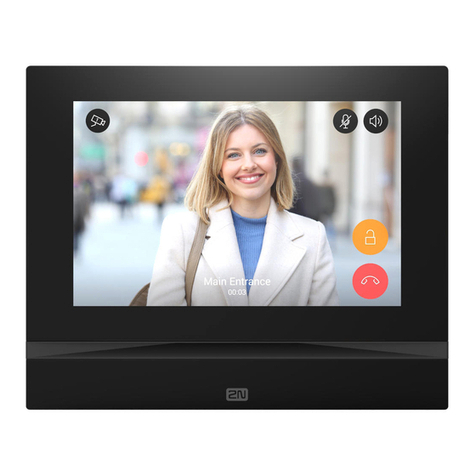
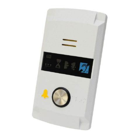
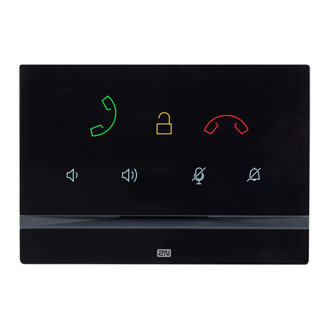
2N®Clip is an indoor IP/SIP unit providing audio/video communication with the 2N IP intercoms.
The device includes a three-button control panel, Speakerphone, high-quality microphone with
excellent audibility and intelligibility properties, Ethernet LAN interface and external power
supply and doorbell connectors.2N®Clip is a top-quality, cost efficient and easy to install and
configure indoor answering unit. One installation can combine variable answering units
manufactured by 2N Telekomunikace a.s.
2N®Clip is equipped with a web administrator interface of its own, which provides enhanced
user comfort and security during use.
Basic properties of2N®Clip:
2 mm thick Plexiglass display
LAN interface with PoE supply option,
easy flush mounting,
the device can be combined in installations with the 2N®IndoorTouch, 2N®
IndoorCompactand 2N®IndoorTalk answering units,
remote administration and configuration via 2N®RemoteConfiguration,
device lock,
remote door lock control
time display,
integrated administrator web interface,
integrated induction loop version option,
external doorbell button input.

2N® Clip User Manual
4 / 75
•
•
•
•
•
•
•
•
•
1.2 Main Units and Accessories
2N®Clip Indoor Units
Part No.
9138511 2N®Clip
An indoor IP/SIP unit providing audio and video communication with the
2NIP intercoms
Part No.
9138512 2N®Clip with induction loop
An indoor IP/SIP unit providing audio and video communication with the
2NIP intercoms
Integrated induction loop
Mounting Accessories
Part No.9138003 US mounting metal holder for 2N®Clip
Not included in the package of 2N®Clip
Part No. 9138002 2N®Clip stand
Not included in the package of2N®Clip

2N® Clip User Manual
5 / 75
•
•
•
•
•
•
•
1.3 Terms and Symbols Used
The following symbols and pictograms are used in the manual:
1.4 Safety Precautions
The manufacturer reserves the right to modify the product in order to improve its qualities. The
manufacturer continuously responds to the clients' requirements by improving the software.
Refer to the 2N.com company websites for the latest 2N®Clip firmware and User Manual.
Where necessary, the device can be installed at a safe distance from the prohibited area
and an Ethernet cable can only be carried to the required site.
Install the device out of reach of sensitive devices and human bodies as it emits
electromagnetic interference.
Refer to Technical Parameters for the allowed range of working temperatures.
The device may not be operated at places exposed to direct sunlight or near heat sources.
The device is designed for indoor use. It may not be exposed to rain, flowing water,
condensing moisture, fog, etc.
The device may not be exposed to aggressive gas, acid vapors, solvents, etc.
It is designed for LAN connection.
•
Safety
Always abide by this information to prevent persons from injury.
•
Warning
Always abide by this information to prevent damage to the device.
•
Caution
Important informationfor system functionality.
•
Tip
Useful informationfor quick and efficient functionality.
•
Note
Routines or advice for efficient use of the device.

2N® Clip User Manual
6 / 75
Caution
This product and its installation and configuration techniques are not intended for
persons with diminished physical, sensory or mental capacities or persons with limited
experience and knowledge unless expertly supervised or duly advised as to the use of
this product by a person responsible for their safety.

2N® Clip User Manual
7 / 75
1.
2.
3.
2. Device Description
This subsection provides the product package content and description of the device elements.
Please check the product delivery before installation. Contents:
1x 2N®Clip
1x Certificate of ownership
1x Quick Start manual
1x metal holder
2x holder fitting screws
1x doorbell connection terminal (removable)
Front Layout
Microphone
Display
Lock button –

2N® Clip User Manual
8 / 75
4.
5.
6.
1.
2.
3.
4.
5.
Speaker button –
Speaker
Earphone button –
Backside Layout
RESET Button
Doorbell button input
LAN Ethernet/POE
Status LEDs
Locking latch

2N® Clip User Manual
9 / 75
•
•
•
•
•
•
•
•
3. Mechanical Installation
This section provides instructions for a proper installation and connection of 2N®Clip.
The device can be installed in one of the following ways:
onto a wall using a KU68 mounting box (not included in the package),
onto a wall using a metal holder,
into a stand.
3.1 Installation Conditions
3.2 On-Wall Installation
3.3 Stand Installation
3.4 Device Removal
3.5 Power Supply
1.
2.
Warning
Having unpacked 2N®Clip, remove the metal holder for installation. Use both your
hands at the same time to remove it safely. A careless removal and insufficient push
might lead to a locking latch damage. Hence, follow the mentioned metal holder
instructions below closely!
Push the locking latch in the center of the device
bottom edge with your left hand in such a manner that
it bends sufficiently for the metal holder removal. Do
not push the locking latch from the top. You might get
injured while removing the metal holder.
Grasp the metal holder with your right hand and slide it
downwards for removal.

2N® Clip User Manual
10 / 75
•
•
•
•
•
•
•
•
•
•
•
•
•
•
3.1 Installation Conditions
Make sure that the following2N®Clip installation conditions are met:
There must be enough space for the device installation.
The device is designed for vertical wall mounting (perpendicular to the floor) in the height
of up to 120 cm above the floor.If necessary, operate the device in a position other than as
aforementioned for a short time only, for quick testing purposes in a servicing center, for
example.
Exceeding the allowed operating temperature may not affect the device immediately but
leads to premature ageing and lower reliability. For the acceptable range of operating
temperatures and relative humidity values refer to 8. Technické parametry.
The device is not designed for environments with increased vibrations such as means of
transport, machine rooms and so on.
The device is not intended for dusty environments and places with unstable humidity and
abrupt temperature changes.
Thedevice may not be exposed to aggressive gas, acid vapors, solvents, etc.
The device is not intended for direct connection into the Internet/WAN.
The device must be connected to the Internet/WAN via a separating active network
element (switch/router).
The device is designed for indoor use. It may not be exposed to rain, flowing water,
condensing moisture, fog, etc.
The device cannot be operated on places exposed to direct sunshine and near heat
sources.
Keep some free space above and below the device to allow air to flow and conduct heat
away.
No strong electromagnetic radiance is allowed on the installation site.
Make sure that the VoIP connection is configured properly according to the SIP and other
VoIP recommendations.
It is recommended that the power adapter be connected to the mains via a UPS and
reliable overvoltage protection.

2N® Clip User Manual
11 / 75
•
3.2 On-Wall Installation
For on-wall mounting, install the flush mounting box first into which the device is subsequently
mounted.
Here is what you can find in this section:
3.2.1 Flush Mounting Box Installation of Device
1.
2.
Warning
Having unpacked 2N®Clip, remove the metal holder for installation. Use both your
hands at the same time to remove it safely. A careless removal and insufficient push
might lead to a locking latch damage. Hence, follow the mentioned metal holder
instructions below closely!
Push the locking latch in the center of the device
bottom edge with your left hand in such a manner that
it bends sufficiently for the metal holder removal. Do
not push the locking latch from the top. You might get
injured while removing the metal holder.
Grasp the metal holder with your right hand and slide it
downwards for removal.

2N® Clip User Manual
12 / 75
3.2.1 Flush Mounting Box Installation of Device
2N®Clip can be installed into a KU 68 flush mounting box using a metal holder (included in the
package), the recommended height of a standard installation being 135 cm from the ground
level. The installation heights may vary depending on the device use. The device can also be
installed directly on a wall without a mounting box.
1.
2.
Warning
Having unpacked 2N®Clip, remove the metal holder for installation. Use both your
hands at the same time to remove it safely. A careless removal and insufficient push
might lead to a locking latch damage. Hence, follow the mentioned metal holder
instructions below closely!
Push the locking latch in the center of the device
bottom edge with your left hand in such a manner that
it bends sufficiently for the metal holder removal. Do
not push the locking latch from the top. You might get
injured while removing the metal holder.
Grasp the metal holder with your right hand and slide it
downwards for removal.
Tip
Drilling Template

2N® Clip User Manual
13 / 75
1.
2.
3.
a.
b.
c.
4.
Draw the pre-prepared LAN connector leading from the wall through the metal holder.
Make sure that it is properly oriented for device connection after mounting.
Level the holder as required using a water level and drill it into the mounting box. The wall
mounting screws are not part of the delivery, the included screws are only for the
mounting box installation.
Connect the LAN connector to the device.
Put the device under the holder with its bottom edge first. Then put the device
vertically on the wall keeping the device bottom edge under the holder.
Slide the device gently downwards along the wall.
Lock the latch to fit the device completely.
Now the device is ready for basic operation.It is necessary to perform software
configuration to achieve full functionality of the device.
Tip
Make sure to ensure the proper orientation while installing the holder on the wall.
To do this, mark the bulge profile on the holder bottom side.

2N® Clip User Manual
14 / 75
1.
2.
3.
a.
You are advised to use a metal holder (not included in the package) for 2N®Clip installation in
the USA. With the aid of this holder, the device can be installed into a universal US single-gang
mounting box. The device can also be installed directly onto a wall without a mounting box.
Draw the pre-prepared LAN connector leading from the wall through the metal holder.
Make sure that it is properly oriented for device connection after mounting. If necessary,
align the holder using a level and drill it into the mounting box or on the wall. The wall
mounting screws are not part of the delivery, the included screws are only for the
mounting box installation.
Connect the LAN connector to the device.
Put the device under the holder with its bottom edge first. Then put the device
vertically on the wall keeping the device bottom edge under the holder.
Tip
Drilling Template

2N® Clip User Manual
15 / 75
b.
c.
Slide the device gently downwards along the wall.
Lock the latch to fit the device completely.
Now the device is attached properly. There is a slight distance between the device and the wall
due to a rather big size of the metal holder, which is fully compliant with the installation
instructions.
Now the device is ready for basic operation.It is necessary to perform software configurationto
achieve full functionality of the device.

2N® Clip User Manual
16 / 75
3.3 Stand Installation
Alternatively, the device can be installed into a stand placed on a desk, for example. The stand is
not included in the package.
Within installation preparations, take out the pre-prepared cabling, UTP cable, doorbell (twin)
cable and power supply. Shorten the cables to the required length. Crimp the RJ-45 connector
onto the UTP cable. Connect the doorbell twin cable together with the LAN connector to the
connector.
1.
2.
Warning
Having unpacked 2N®Clip, remove the metal holder for installation. Use both your
hands at the same time to remove it safely. A careless removal and insufficient push
might lead to a locking latch damage. Hence, follow the mentioned metal holder
instructions below closely!
Push the locking latch in the center of the device
bottom edge with your left hand in such a manner that
it bends sufficiently for the metal holder removal. Do
not push the locking latch from the top. You might get
injured while removing the metal holder.
Grasp the metal holder with your right hand and slide it
downwards for removal.

2N® Clip User Manual
17 / 75
1.
2.
Draw the pre-prepared LAN connector through the stand bottom and connect it into the
LAN connector socket. Place the cable into the pre-prepared groove in the center of the
stand bottom. Unstick the protective foil from the stand antislip surfaces.
Put the stand including the properly drawn and connected cable on the device. First snap
in the stand hooks, then tilt the stand towards the device and lock the latch on the stand
top edge into the device body.
Now the device is ready for basic operation. It is necessary to perform software configuration to
achieve full functionality of the device.
To remove the device from the stand, reverse the steps - start by releasing the locking latch on
the top edge of the stand.
3.4 Device Removal
Caution
We recommend that you use a CAT5e UTP cable to fit the stand bottom groove
size.

2N® Clip User Manual
18 / 75
1.
2.
Press the locking latch located in the center of the device back bottom edge. Pull the
device gently upwards to release it from the metal holder/stand.
Remove the device from the hooks and take it away safely.
3.5 Power Supply
2N®Clip is fed via an Ethernet cable connected to a PoE power supply or PoE supporting
Ethernet switch/router.
Supply type
PoE, IEEE 802.3af
3.5.1 PoE Supply Connection
Use a standard straight RJ-45 terminated cable to connect 2N®Clip to the Ethernet. The device
supports the 10BaseT and 100BaseT protocols.
Ethernet cable connector Ethernet socket
Upozornění
The external power supply should meet the PS2/LPS power supply class.
•
•
Warning
Do not connect any external power supply if PoE is used and vice versa.
Connection of a defective or improper power supply may lead to a temporary or
permanent device failure.
•
•
Caution
Factory reset results in a change of the Ethernet interface configuration.
A defective Ethernet cable may lead to a high packet loss in the Ethernet and
subsequent instability and poor call quality.

2N® Clip User Manual
19 / 75
Warning
This device cannot be connected directly to telecom lines (or public wireless networks)
of any telecom service providers (i.e. mobile providers, landline providers or Internet
providers). A router has to be used for the device Internet connection.

2N® Clip User Manual
20 / 75
•
•
•
•
•
•
•
•
•
•
4. Quick Guide
This section describes access to the 2N®Clip configuration web interface, firmware upgrade
procedure and factory default reset.
4.1 Device Configuration Interface Access
4.2 IP Address Retrieval
4.3 Firmware Update
4.4 Factory Default Reset
4.1 Device Configuration Interface Access
2N®Clip is configured via the administration web interface. Connect the device to the LAN IP
and make sure it is properly powered. You have to know the device IP address to gain access.
Retrieve the IP using one of the three methods described in IP Address Retrieval:
use the freely accessible 2N®Network Scanner application,
show the information directly on the device display,
use hardware (RESET button).
4.1.1 Web Interface Login
Fill in the 2N®Clip address or domain name into the Internet browser. The login screen is now
displayed.
The default login data are:
Username: Admin
Password: 2n
Should the login screen fail to appear, you must have typed a wrong IP address/port into the
Internet browser or the 2N®Clip administration web server has been switched off. If you are not
certain about the IP address, find it as described in IP Address Retrieval.
4.2 IP Address Retrieval
To retrieve the device IP address, take the following steps:
use the freely accessible 2N®Network Scanner application,
show the information directly on the device display,
use hardware (RESET button).
This manual suits for next models
2
Table of contents
Other 2N Intercom System manuals