3M Speedglas G5-02 User manual

3G5-02
Speedglas™
Welding Helmet
User Instructions
Masques pour soudeur
Directives d’utilisation
Casco para soldar
Instrucciones de uso
IMPORTANT: Before use, the wearer must read and understand these User Instructions. Keep these User
Instructions for reference.
IMPORTANT : Avant de se servir du produit, l’utilisateur doit lire et comprendre les présentes directives
d’utilisation. Conserver ces directives d’utilisation à titre de référence.
IMPORTANTE: Antes de usarlo, el usuario debe leer y comprender estas Instrucciones de uso. Conserve estas
Instrucciones de uso para su consulta.
G5-02

CONTENTS
FOREWORD...........................................................................................................................................................1
Contact Information.....................................................................................................................................1
System Description .....................................................................................................................................1
List of Warnings within these User Instructions............................................................................................1
Limitations of Use........................................................................................................................................2
Additional Certications...............................................................................................................................3
Specications..............................................................................................................................................3
OPERATING INSTRUCTIONS...................................................................................................................................4
Unpacking ...................................................................................................................................................4
Assembly ....................................................................................................................................................4
Donning & Fitting ........................................................................................................................................4
Auto-Darkening Filter Function ...................................................................................................................7
Preparation for Use......................................................................................................................................7
INSPECTION & MAINTENANCE.............................................................................................................................11
REPLACEMENT PARTS AND ACCESSORIES .........................................................................................................16
CLEANING, STORAGE, AND DISPOSAL.................................................................................................................19
EXPECTED LIFE ..................................................................................................................................................20
TROUBLESHOOTING............................................................................................................................................20
FCC .....................................................................................................................................................................22
IC ........................................................................................................................................................................22
WARRANTY..........................................................................................................................................................22

1
FOREWORD
Contact Information
Read all instructions and warnings before using. Keep these User Instructions for reference. If you have questions
regarding these products contact 3M Technical service.
In United States: In Canada:
Website: www.3M.com/workersafety
Technical Service: 1-800-243-4630
Website: www.3M.ca/Safety
Technical Service: 1-800-267-4414
System Description
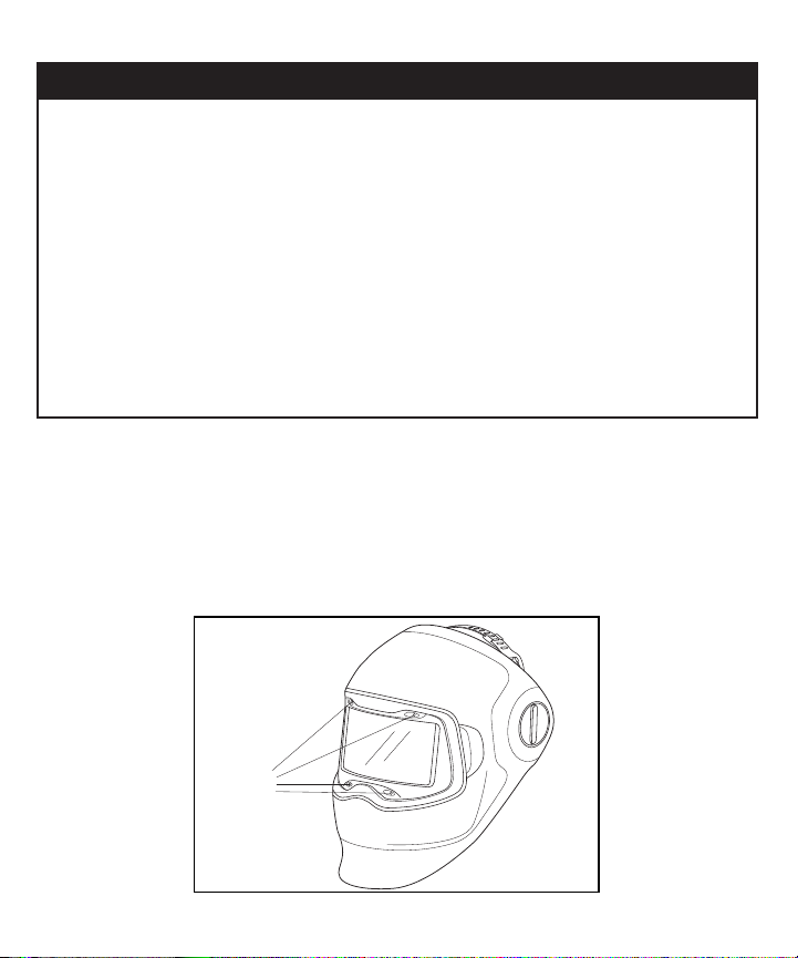
The 3M™ Speedglas™ Welding Helmet G5-02 helps protect the wearer’s eyes and face. It gives permanent
protection from sparks/spatter, UV and IR radiation resulting from certain arc/gas welding processes (shade 12
equivalent regardless of whether the lter is in the light or dark state or whether the auto-darkening function is
operational).
List of Warnings within these User Instructions
WWARNING
1. This product meets the requirements of certain industrial eyewear and face protection standards. It
does not provide complete eye and face protection from signicant impact and penetration and is not
a substitute for good safety practices and engineering controls. Misuse may result in serious bodily
injury or death. For correct use, consult your supervisor and User Instructions or contact 3M Technical
Service in the U.S.A. at 1-800-243-4630. In Canada, call Technical Service at 1-800-267-4414.
2. This product is not a respirator. Welding may produce high levels of welding fume or other airborne
contaminants which may exceed the Occupational Exposure Limit (OEL). As a result, users and their
employer must determine the expected hazards, and if needed select appropriate respiratory protection.
Properly selected, used, and maintained respirators in a full respiratory protection program help protect
against certain airborne contaminants by reducing airborne concentrations in the wearer’s breathing
zone below the OEL. Failure to use respirators or misuse of respirators may result in overexposure to
contaminants and lead to sickness or death.
3. Do not use any welding product without appropriate training.
4. When exposed to eye and face hazards, wear additional eye and/or face protectors appropriate to the
hazard. ANSI Z87.1 – Occupational and Educational Eye and Face Protection, incorporated by reference in
the OSHA Eye and Face Standard 29 CFR 1910.133, requires safety spectacles or goggles to be worn in
conjunction if the visor can be raised from the normal position during use. Failure to do so may result in
serious bodily injury or death.
5. Failure to follow these instructions may reduce the capability of the 3M™ Speedglas™ Welding
Helmet G5-02 shell to withstand impact and penetration and may result in serious bodily injury or death:
a. Use only the cleaning processes and agents described in these User Instructions to clean the shell.
b. Do not immerse in water or spray directly with liquids.
c. This welding helmet must not be painted or cleaned with solvents. Any decals applied to the
welding helmet must be compatible with the surface material and known not to affect adversely
the characteristic of the materials used in the welding helmet. Decals may affect the impact and
ammability characteristics of this welding helmet and prevent inspection for damage under decals.

2
WWARNING
6. Should the 3M™ Speedglas™ Auto-Darkening Filter G5-02 fail to switch to dark mode upon striking
an arc, stop welding immediately and inspect the welding lter as described in these User Instructions.
Continued use of a welding lter that fails to switch to the dark state may result in permanent eye
injury and vision loss. If the problem cannot be identied and corrected, do not use the welding lter;
contact your supervisor, distributor or 3M for assistance.
7. Cracked, pitted or scratched lter glass or protection plates may reduce vision and can seriously impair
protection. All damaged components should be replaced immediately. Ensure that your welding lter is
equipped with an outer/inner protection/cover plate.
8. The 3M™ Speedglas™ Welding Helmet G5-02 is not suitable for laser welding or welding processes that
require lters greater than Shade 12. Use of this product for these applications may result in permanent
eye injury and vision loss.
Limitations of Use
WWARNING
1. Severe burn injuries may result if this welding helmet is used for heavy-duty overhead welding
applications where there is a potential for falling molten metal.
2. This product is not a respirator. Welding may produce high levels of welding fume or other airborne
contaminants which may exceed the Occupational Exposure Limit (OEL). As a result, users and their
employer must determine the expected hazards, and if needed select appropriate respiratory protection.
Properly selected, used, and maintained respirators in a full respiratory protection program help protect
against certain airborne contaminants by reducing airborne concentrations in the wearer’s breathing
zone below the OEL. Failure to use respirators or misuse of respirators may result in overexposure to
contaminants and lead to sickness or death.
3. This welding helmet is not suitable for laser welding or welding processes that require lters greater than
Shade 12.
4. This welding helmet is not suitable for grinding operations.
5. Only operate the welding helmet system at temperatures between 23°F (–5°C) and 131°F (+55°C).
6. Do not use the welding helmet system in areas where contact with an open ame is possible.
7. The welding helmet is heat resistant but can catch re or melt in contact with open ames or very hot
surfaces. Keep the shield clean to minimize this risk.
8. These products are not formulated with natural rubber latex.
9. Do not immerse in water or spray directly with liquids.
10. Carefully check that the product is complete, undamaged and correctly assembled. Any damaged or
defective parts must be replaced before each use. Check for cracks and look for light leaks..

3
Additional Certications
WWARNING
1. This product meets the requirements of certain industrial eyewear standards. It does not provide complete
head, eye, and face protection from signicant impact and penetration and are not a substitute for good
safety practices and engineering controls. Misuse may result in serious bodily injury or death. For
correct use, consult your supervisor and User Instructions or contact 3M Technical Service in the U.S.A. at
1-800-243-4630. In Canada, call Technical Service at 1-800-267-4414.
2. When exposed to eye and face hazards, wear additional eye and/or face protectors appropriate to the
hazard. ANSI Z87.1 – Occupational and Educational Eye and Face Protection, incorporated by reference in
the OSHA Eye and Face Standard 29 CFR 1910.133, requires safety spectacles or goggles to be worn in
conjunction with the welding helmet if the visor can be raised from the normal position during use. Failure
to do so may result in serious bodily injury or death.
When assembled according to these User Instructions, this welding helmet meets requirements of the ANSI
Z87.1.
Occupational use of this product for eye and face and/or head protection must be in compliance with applicable
health and safety standards. In the US, employers must comply with the OSHA personal protective equipment (PPE)
standard (29 CFR 1910.132) and, as applicable, the eye and face standard (29 CFR 1910.133). In Canada, consult
the applicable standard(s) for your jurisdiction.
Specications
NOTE: The 3M™Speedglas™Welding Helmet G5-02 is not formulated with natural rubber latex.
Table 1. Specications for 3M™Speedglas™Welding Helmet G5-02
Technical Data
Approximate Viewing Area
5.9 x 3 in.
150 x 76mm
Approximate Welding Filter
Battery Life
(1 x CR-2450N) 1500
Solar Assist No
Welding Helmet Weight (w/
headband and welding lter) 18.87oz. (535g)
Dark Shades 8, 9, 10, 11, 12,
Light State Shade 2.5
Switching Speed 0.1 milliseconds at 73F (23C)
Sensitivity Modes 6 levels

4
Table 1 Continued. Specications for 3M™Speedglas™Welding Helmet G5-02
Number of Sensors 4
Delay (Recovery) Adjustable 50 – 1000 milliseconds (approx.)
Welding Helmet & Welding Filter
Operating Temp Range 23°F to 131°F (-5°C to 55°C) RH ≤ 90%
Standards Compliance ANSI Z87.1
Auto-Darkening Filter Warranty 3 Years
Welding Helmet Warranty 90 Days
Head sizes 6 3/8 to 8 (50-64 cm)
Welding Helmet Polyphthalamide (PPA),
Auto-Darkening Filter Polyamide (PA), Thermoplastic Elastomer (TPE), Polycarbonate (PC)
Welding Helmet Headband Polyamide (PA), Polypropylene (PP),Thermoplastic Elastomer (TPE)
Visor & Protection Plates Polycarbonate (PC)
Storage Temperature Range* -22°F to 122°F (-30°C to 55°C) RH ≤ 90% *
*-4°F to 131°F (-20°C to 55°C) suggested storage temperature range if product will be stored for an extended
period of time before rst use without batteries. Lithium batteries are suggested to be stored for long term at
50°F to 77°F (10°C to 25°C) RH ≤ 60%.
OPERATING INSTRUCTIONS
Unpacking
Inspect the package contents for shipping damage and ensure all components are present. The product should
be inspected before each use following the procedures in the Inspection & Maintenance section of these User
Instructions. Any damaged or defective parts must be replaced before use.
Assembly
3M™Speedglas™Welding Helmet G5-02
Prior to use, ensure any protective coverings or lms that may have been placed over the clear protection plates
or viewing surfaces of the auto-darkening lter viewing areas to protect it during manufacturing or shipping are
removed.
Donning & Fitting
1. With the helmet in the up position, place the welding helmet on your head.
2. Turn the ratchet knob at the back of the suspension clockwise until the suspension feels snug but
comfortable. Turn counterclockwise to loosen, if needed. The suspension ts head sizes from 50-64 cm
(US hat sizes 6 3/8 to 8). Adjust the top part of the suspension for added comfort (Fig. 1a). To make initial
adjustment of the head suspension easier (and for replacement) it may be removed from the welding helmet.
Pull the locking tab towards the outside of the helmet and slide the suspension out (Fig. 1b). To replace the
head suspension, line the tracks on the head suspension up with the slide mechanism. Pull the locking

5
tabs towards the outside of the helmet and slide the suspension forward, making sure to lock the sliding
mechanism in place (Fig. 1c).
Printed Colors – Front:
Requester: Farrel Allen
Creator: deZinnia_25675
File Name: 25671-02_G5-02_Tighten Cradle_PSD.ai
Structure #: Illustration
Date: 06/10/19
This artwork has been created as requested by 3M. 3M is responsible for the artwork
AS APPROVED and assumes full responsibility for its correctness.
Scale:
1 Inch
3. An optional size large comfort head rest (46-0400-55) that will t to the ratchet is available. This large
comfort head rest can also be used to improve t and stability for smaller head sizes (Fig. 2).
1.
2.
3.
4. The resting tilt of the welding helmet (how far downward the lens settles) and the distance from the face may
also be adjusted.
a. At the right-side pivot point there is a small lever to stop the downward travel of the welding helmet.
At the high position the welding helmet will come to rest so the welder can weld slightly above eye
level. At the low position the welding helmet will face at a slightly downward angle (Fig. 3a). With the
welding shield in the up position, push the lever in toward the head and adjust it up or down. Bring
the shield down to the stopping point to see where it rests.
b. To adjust the welding helmet in and out (closer and further from the face) there are two slides on
either side of the head suspension. To unlock the slides, push out on the blue buttons with your
thumbs and slide the welding helmet out or in, adjusting to your personal preference (Fig. 3b). This
adjustment will help with safety glasses spacing and also magnication lens distance.
Fig. 1a Fig. 1b Fig. 1c
Fig. 2

6
≈10-12°
G5-02
G5-02
Position D Position C Position B Position A
5. The amount of force necessary to lift the helmet may be adjusted.
a. To adjust the drop force or friction, turn both pivot knobs labeled FRICTION clockwise to increase or
counter-clockwise to decrease the friction (Fig. 4).
G5-02
DROP-
FRICTION
+
_
Fig. 3a Fig. 3b
Fig. 4

7
Auto-Darkening Filter Function
WWARNING
1. Should the 3M™ Speedglas™ Auto-Darkening Filter G5-02 fails to switch to dark mode upon striking
an arc, stop welding immediately and inspect the welding lter as described in these User Instructions.
Continued use of a welding lter that fails to switch to the dark state may result in permanent eye
injury and vision loss. If the problem cannot be identied and corrected, do not use the welding lter;
contact your supervisor, distributor or 3M for assistance.
2. Carefully inspect the complete 3M™ Speedglas™ Auto-Darkening Filter G5-02 before each use. Cracked,
pitted or scratched lter glass or protection plates reduce vision and can seriously impair protection. All
damaged components should be replaced immediately. Remove any protective lm from the welding lter
before initial use.
3. The 3M™ Speedglas™ Auto-Darkening Filter G5-02 is not suitable for laser welding or welding
processes that require lters greater than Shade 12. Likewise, the G5-02 is not suitable for grinding.
Use of this product for these applications may result in permanent eye injury, vision loss, and other
serious injury.
4. Only operate the welding helmet at temperatures between 23°F (–5°C) and 131°F (+55°C). If used
outside of this range, the system may not perform as designed and may result in serious bodily injury,
sickness or death.
Preparation for Use
On/Off
The welding lter is motion sensitive and will automatically turn ON when moved. During its initial power-up,
all of the adjustment lights will cycle quickly, one at a time. The welding lter automatically turns OFF after
1 hour of inactivity. The welding lter has four photo sensors that react independently and cause the lter to
darken when a welding arc is struck (Fig. 5). The welding lter may not turn dark if the sensors are blocked
or the welding arc is totally shielded. Flashing light sources (e.g. safety strobe lights) can trigger the welding
lter making it darken when no welding is occurring. This interference can occur from long distances and/or
from reected light. Welding areas must be shielded from such interference.
G5-02
Light
sensor
Fig. 5

8
SHORT
LONG
2
1
3
4
5
6
DELAY
HIGH
6
5
SHORT
2
1
6
5
SENS
LOW
4
3
2
1
A
SHADE
LOCK
B
EF
D
C
SHADE
AUTO
ON
9
8
10
11
12
Printed Colors – Front:
Requester: Farrel Allen
Creator: deZinnia_26273
File Name: 26273-01_G5-02_ADF_Expld_PSD.ai
Structure #: Illustration
Date: 10/30/19
This artwork has been created as requested by 3M. 3M is responsible for the artwork
AS APPROVED and assumes full responsibility for its correctness.
Scale:
1 Inch
Shade
a. Five different shade settings are available, 8-12.To see the current shade setting, quickly press and release
the SHADE +or -button. The current shade number will blink. To change shade, press the +or -button
repeatedly to move the ashing LED up or down to the desired shade (Fig. 6a).
NOTE: When turned off (or if the battery fails) the welding lter reverts to Shade 2.5. When functioning, the
welding lter cycles between the selected shade and Shade 2.5.
b. The shade may be LOCKED in a desired dark shade by pressing the SHADE LOCK button (Fig. 6b). To come
out of the LOCKED state, press the SHADE LOCK button again. While LOCKED, the shade may be adjusted,
but none of the other function (sensitivity or delay) will operate.
NOTE: In all welding processes, the arc should only be viewed with the recommended shade darkness (Table 2).
If the recommended shade is greater than 12, the G5-02 welding helmet should not be used.
Fig. 6

9
Table 2. Recommended Guide for Shade Numbers (Adapted from ANSI Z49.1-2012)
Operation Electrode Size in.
(mm) Arc Current
(Amps)
Minimum
Protective
Shade
Recommended*
Shade Number
Shielded Metal Arc Welding
(SMAW) Less than 3/32 (2.4) < 60 7 —
3/32 – 5/32 (2.4 – 4.0) 60-160 810
5/32 – 1/4 (4.0 – 6.4) 160-250 10 12
More than 1/4 (6.4) 250-550 11 14
Gas Metal Arc welding
(GMAW or MIG) and ux
Core Arc Welding (FCAW)
< 60 7 —
60-160 10 11
160-250 10 12
250-550 10 14
Gas Tungsten Arc Welding
(GTAW or TIG) < 50 810
50-150 812
150-500 10 14
Carbon Arc Cutting – Air
(CAC-A) Light < 500 10 12
Heavy 500-1000 11 14
Plasma arc welding (PAW) < 20 66-8
20-100 810
10 12
11 14
Plasma arc cutting (PAC) < 20 4 4
20-40 5 5
40-60 8 8
60-80 8 8
80-300 8 9
300-400 912
400-800 10 14

10
Table 2 Continued. Recommended Guide for Shade Numbers (Adapted from ANSI Z49.1-2012)
Operation Electrode Size in.
(mm) Arc Current
(Amps)
Minimum
Protective
Shade
Recommended*
Shade Number
Torch Brazing (TB) ——3-4
Torch Soldering (TS) — — 2
Carbon Arc Welding (CAW) ——14
Operation Plate Thickness in.
(mm) Recommended*
Shade Number
Oxyfuel Gas Welding (OFW)
Light < 1/8 (< 3) — — 4-5
Medium 1/8 - 1/2 (3-13) — — 5-6
Heavy > 1/2 (> 13) ——6-8
Oxygen Cutting (OC)
Light < 1 (< 25) ——3-4
Medium 1-6 (25-150) ——4-5
Heavy > 6 (> 150) ——5-6
*As a rule of thumb, start with a shade that is too dark to see the weld zone. Then go to a lighter shade which
gives sufcient view of the weld zone without going below the minimum. In oxyfuel gas welding, cutting, or
brazing where the torch and/or the ux produces a high yellow light, it is desirable to use a lter lens that
absorbs the yellow or sodium line of the visible light spectrum.
Sensitivity Selection
The sensitivity of the arc detection system can be adjusted to accommodate a variety of welding processes and
workplace conditions.
a. In order to see the current sensitivity setting, quickly press and release the SENS +or -button. The current
sensitivity number will blink. To change sensitivity, press the SENS +or -button repeatedly to move the
ashing LED up or down to the desired sensitivity (Fig. 6c).
b. The settings correspond to:
6 High – Most sensitive, for low energy TIG welding or where part of the arc may be obscured from view
5 Medium High – Very low current welding, use of TIG welding machines.
4 Medium – For low current welding, use of TIG welding machines.
3 Normal – For low current, with stable welding arcs or bright ambient light.
2 Low – Used for most types of welding.
1 Very Low – Least sensitive setting. Used if there is interference from other welders’ arcs in the vicinity.
c. If the welding lter does not switch to the dark state during welding as desired, increase the sensitivity.
Should the sensitivity be set too high, the welding lter may remain in the dark state after welding is stopped

11
due to ambient light. In this case decrease the sensitivity. The sensitivity cannot be adjusted when in
LOCKED mode.
NOTE: The higher the sensitivity setting, the higher the sensitivity. At the highest sensitivity, even the smallest
amount of light change (light from surrounding welders, strobe lights, reected glare, etc.) will trigger the welding
lter to darken. If the welding lter is triggering when it is not supposed to, a lower sensitivity setting may be
needed.
Delay
The delay function allows the user to manually increase or decrease the recovery delay time (going from dark,
back to light) according to the requirements of the welding process to reduce eye fatigue. A longer delay may
help protect the eyes from the bright light of a large, hot weld puddle. G5-02 has six different settings.
a. To see the current delay setting, quickly press and release the DELAY button. The current delay number will
blink. To change the delay, press the DELAY button repeatedly to move the ashing LED up to the desired
delay. Once the DELAY reaches level 6, press the DELAY button and it will cause the welding lter to cycle
back to level 1 (Fig. 6d).
Bluetooth®
The welding lter can be paired with and connected to iOS™ and Android™ devices via the 3M™ Connected
Equipment App using Bluetooth® (Fig. 6e). The app can be downloaded from the iOS™ App Store® or Google
Play™ store. For information on how to connect the app with the welding lter, follow the User Instructions in the
app. When connected to the iOS™ or Android™ device, the user will have access to welding lter settings, work
statistics, etc.
Low Battery Indicator
The battery should be replaced when the low battery indicator ashes or LEDs do not ash when the buttons
are pressed (Fig. 6f). See the Inspection & Maintenance section for information regarding removing the
welding lter and replacing the battery.
INSPECTION & MAINTENANCE
WWARNING
1. Do not use with parts or accessories other than those manufactured by 3M as described in these User
Instructions.
2. Failure to follow these instructions may reduce the capability of the 3M™ Speedglas™ Welding
Helmet G5-02 shell to withstand impact and penetration and may result in serious bodily injury or
death.
a. Any part of the welding helmet damaged due to signicant impact should be replaced.
3. The used battery/worn out product parts should be disposed of according to local regulations. The welding
lter should be disposed of as electronic waste.
Before and after each use, inspect entire welding helmet for signs of damage or wear including dents, rips,
cracks, color changes, chalking, fading, aking and/or penetration. Carefully inspect all helmet components
including the following:
1. Welding Helmet Shell: Look for visible damage including dents, cracks, color change, chalking, fading,
aking and/or penetration. Any welding helmet subjected to signicant impact should be removed from
service and replaced even if damage is not readily apparent.
2. Headgear Suspension: Look for cracks, rips, fading, or other damage. Ensure headgear suspension ratchet
operates properly. Inspect the overhead plastic adjustment straps for cracks or damage. Look at sweatband

12
to make sure it is in good working order. Ensure suspension is properly attached and pivots easily. See
Welding Helmet Donning & Fitting section (above) for instruction regarding removal and replacement of the
head suspension.
3. Outer protection plate and front cover: Look for scratches or other visual distortions that could make it
difcult to see through the outside protection plate. Look for signs that the outside protection plate or front
cover has warped or cracked. Make sure it is installed correctly and replace as necessary. To replace the
outer protection plate and front cover:
a. Lift on the tab on the side of the front cover to remove it from the welding helmet (Fig. 7a).
b. While looking at the front of the welding helmet, grasp the outside edge of the protection plate and
pull out to release the tabs. (Fig. 7b).
G5-02
G5-02
Printed Colors – Front:
Requester: Farrel Allen
Creator: deZinnia_26274
File Name: 26274-01_G5-02_GrdShieldRmvl_PSD.ai
Structure #: Illustration
Date: 10/23/19
This artwork has been created as requested by 3M. 3M is responsible for the artwork
AS APPROVED and assumes full responsibility for its correctness.
Scale:
1 Inch
Fig. 7a
Fig. 7b

13
c. To reinstall a new protection plate, hook the tabs into their slots on the welding helmet (Fig. 8).
G5-02
d. To reinstall the protection front cover, place it over the protection plate and snap it into place at all four
corners using rm, downward and outward pressure from your thumb or index nger (Fig. 9).
G5-02
G5-02
1. 2.
4. Welding Filter:
a. Remove the welding lter by sliding the locking mechanisms on the side up to the unlock position.
Then, lift on the bottom of the welding lter and carefully slide it out of the welding helmet (Fig. 10).
Fig. 9
Fig. 8

14
b. To remove the inside protection plate, lift on the tab on the side of the plate to remove it from the
welding lter. Before inserting a new protection plates, remove any protective lm on the plate and
insert it back into its slots on the welding lter (Fig. 11).
Fig. 10
Fig. 11

15
c. To replace the battery, on the side of the welding lter, locate the small cutout. Pry the battery holder
out with a ngernail or small screw driver. Replace with a new CR2450N disc style battery and
reinsert the battery holder (Fig. 12). All of the indicator lights on the welding lter should illuminate to
give a visual conrmation of power.
1.
2.
d. Reinstall the welding lter into the welding shell by rst aligning the tabs on top, resting the welding
lter in place, and nally sliding the locking mechanisms down into the lock position with an audible
“click” (Fig. 13).
Fig. 12
Fig. 13

16
If you discover any signs of wear and/or damage, remove the welding helmet from use and service or
replace as appropriate. Failure to do so may reduce the degree of protection provided and lead to serious bodily
injury or death.
REPLACEMENT PARTS AND ACCESSORIES
Replacement Parts
WWARNING
1. Failure to follow these instructions may reduce the capability of the 3M™ Speedglas™ Welding Helmet
G5-02 outside protection plate to withstand impact and penetration and may result in serious bodily injury
or death:
• Always wear secondary eye protection for a welding shield system that may be raised in the eld.
G5-02
08-0300-52
18-0099-68
02-0690-00
06-0700-83
08-0400-51
08-0400-52
07-0024-02
Printed Colors – Front:
Requester: Farrel Allen
Creator: deZinnia_26851
File Name: 26851-01_G5-02_ExpldView_Fig 14a_PSD.ai
Structure #: Illustration
Date: 02/18/20
This artwork has been created as requested by 3M. 3M is responsible for the artwork
AS APPROVED and assumes full responsibility for its correctness.
Scale:
1 Inch
08-0700-63 08-0500-56
08-0500-57
08-0500-58
08-0200-52 08-0200-50
08-0000-50iC
Printed Colors – Front:
Requester: Farrel Allen
Creator: deZinnia_26278
File Name: 26278-01_G5-02_ExpldView_Fig 14b_PSD.ai
Structure #: Illustration
Date: 10/21/19
This artwork has been created as requested by 3M. 3M is responsible for the artwork
AS APPROVED and assumes full responsibility for its correctness.
Scale:
1 Inch
Fig. 14a—Spare Welding Helmet Parts
Fig. 14b—Spare Welding Filter Parts

17
Table 3. Assemblies, Acceessories and Spare Parts
3M™ Speedglas™ Complete System Assemblies
08-0100-50iC 3M™ Speedglas™ G5-02 Welding Helmet, with Curved Auto-Darkening Filter,
Headband, Cleaning Wipe and Bag
3M™ Speedglas™ Welding Helmet Shell (without Auto-Darkening Filter)
08-0300-52 3M™ Speedglas™ G5-02 Welding Helmet Shell, Without Front Cover, Headband, or
Auto-Darkening Filter
3M™ Speedglas™ Welding Filters
08-0000-50iC 3M™ Speedglas™ G5-02 Curved Auto-Darkening Filter
3M™ Speedglas™ Replacement Parts and Accessories
08-0200-50 3M™ Speedglas™ G5-02 Inside Protection Plate with Integrated Airow Deector
08-0200-52 3M™ Speedglas™ G5-02 Outside Protection Plate, Scratch Resistant
08-0400-51 3M™ Speedglas™ G5-02 Head Suspension Assembly
08-0400-52 3M™ Speedglas™ G5-02 Headband Pivot Mechanism, Left and Right Side
46-0400-55 3M™ Speedglas™ G5-01 Large Comfort Head Rest
08-0500-56 3M™ Speedglas™ G5-02 Magnication Plate 1.5X
08-0500-57 3M™ Speedglas™ G5-02 Magnication Plate 2.0X
08-0500-58 3M™ Speedglas™ G5-02 Magnication Plate 2.5X
08-0700-63 3M™ Speedglas™ G5-02 Welding Helmet Front Cover
SG-96 3M™ Speedglas™ G5-02 Welding Helmet Bag
130100 3M™ Speedglas™ Welding Helmet Cleaning Wipe
07-0024-02 3M™ Speedglas™ Sweatband
02-0690-00 3M™ Speedglas™ Extended Neck Protection
06-0500-51 3M™ Speedglas™ Extended Coverage
06-0700-83 3M™ Speedglas™ Welding Full Hood
16-0099-30 3M™ Speedglas™ Extended Head Cover (black/grey)
18-0099-68 3M™ Speedglas™ Ear and Neck Protection (leather)

18
1. Helmet Pivot and Slide:
To replace the pivot and slide mechanisms:
a. With the headgear suspension removed (see Welding Helmet Donning & Fitting, #2 above), hold the
slide mechanism in one hand, and twist the friction knob until it backs completely out. To replace the
pivot and slide for the left side, align the knob, washer, and slide. For the right side, align the knob, tilt
lever, and slide (Fig 15). Then, twist the friction knob until desired friction is achieved.
2. Magnication Lens: For small applications or for employees that require corrective lenses where
magnication is necessary, the welding lter may incorporate a 1.5x, 2.0x, or 2.5x magnication lens. To add
a lens to the welding lter, align one side of the magnication plate tabs into the inner protection plate slots.
Once inserted, insert the other side by aligning and pressing down until you feel a “click” (Fig. 16).
Fig. 15
Other manuals for Speedglas G5-02
1
Table of contents
Languages:
Other 3M Motorcycle Accessories manuals

3M
3M Versaflo M Series User manual

3M
3M Speedglas 9100V User manual

3M
3M G3000 User manual

3M
3M Speedglas G5-02 User manual

3M
3M Speedglas 9100 MP User manual

3M
3M Speedglas 9100 MP User manual

3M
3M L-705 Installation instructions

3M
3M Speedglas 9100 MP User manual

3M
3M G22 User manual

3M
3M Digital Media System 700 Series User manual