R&G SS0054 User manual

Page 1of 10 SS0054
R&G
Unit 1, Shelley’s Lane, East Worldham, Alton, Hampshire, GU34 3AQ
Tel: +44 (0)1420 89007 Fax: +44 (0)1420 87301 www.rg-racing.com Email: info@rg-racing.com
FITTING INSTRUCTIONS FOR SS0054 SPINDLE SLIDERS
TO FIT YAMAHA XTZ 700 (TENERE) 2019
Picture A Picture B
This Kit contains the items pictured and labelled over page.
Some parts may be shown for clarity of instructions only.
Do not proceed until you are sure all parts are present.
Please read all instructions before proceeding.
IF IN ANY DOUBT WHEN FITTING OUR PRODUCTS, CONSULT ONE OF OUR DEALERS
OR HAVE FITTED BY AQUALIFIED TECHNICIAN.
Please note that the way the kit is packed does not necessarily represent the way of
mounting to the bike.
In the event of rubber washers being used to hold components onto bolts,
these rubber washers can be thrown away.
DIGITAL COPIES OF THESE INSTRUCTIONS ARE AVAILABLE FROM
www.rg-racing.com

Page 2of 10 SS0054
R&G
Unit 1, Shelley’s Lane, East Worldham, Alton, Hampshire, GU34 3AQ
Tel: +44 (0)1420 89007 Fax: +44 (0)1420 87301 www.rg-racing.com Email: info@rg-racing.com
TOOLS REQUIRED
•Socket Set to Include 2 x 10mm sockets
and wrenches.
•Small amount of superglue or Loctite.
GENERAL TORQUE SETTINGS
M4 BOLT = 8Nm
M5 BOLT = 12Nm
M6 BOLT = 15Nm
M8 BOLT = 20Nm
M10 BOLT = 40Nm
M12 BOLT = 40Nm
ITEM No.
DESCRIPTION
QTY
ITEM 1
NUT COVERS (NC0007)
2
ITEM 2
B0444 COTTON REEL (WITH CS465—6mm FITTED) (LEFT-HAND-SIDE)
1
ITEM 3
LEFT-HAND-SIDE COTTON REEL SPACER (S1241=24mm LONG)
1
ITEM 4
SPINDLE BAR (SB113=M6 x 392mm LONG)
1
ITEM 5
RIGHT-HAND-SIDE COTTON REEL SPACER (S1242=25mm LONG)
1
ITEM 6
B0444 COTTON REEL (WITH CS324—8mm FITTED) (RIGHT-HAND-SIDE)
1
ITEM 7
M6 NYLOC NUT
2
ITEM 8
M6 WASHER (16mm O/D)
2
LEGEND
1
2
3
5
8
4
7
ASSEMBLY DIAGRAM
6
7
1
8

Page 3of 10 SS0054
R&G
Unit 1, Shelley’s Lane, East Worldham, Alton, Hampshire, GU34 3AQ
Tel: +44 (0)1420 89007 Fax: +44 (0)1420 87301 www.rg-racing.com Email: info@rg-racing.com
CONSUMER NOTICE
The catalogue description and any exhibition of samples are only broad indications of the Products and R&G may make design
changes which do not diminish their performance or visual appeal and supplying them in such state shall conform to the order.
The Buyer acknowledges no representation or warranty (other than as to title) has been given or will apply to the Products other
than those in R&G’s order or confirmation and the Buyer confirms it has chosen the Products as being of merchantable quality
and suitable for its particular purposes. Where R&G fits the Products or undertakes other services it shall exercise reasonable
skill and care and rectify any fault free of charge unless the workmanship has been disturbed. The Buyer is responsible for
ensuring that the warranty on the motorcycle is not affected by the fitting of the Products. On return of any defective Products
R&G shall at its option either supply a replacement or refund the purchase money but shall not be liable if the Products have
been modified or used or maintained otherwise than in accordance with R&G’s or manufacturer’s instructions and good
engineering practice or if the defect arises from accident or neglect. Other than identified above and subject to R&G not limiting
its liability for causing death and personal injury, it shall not be liable for indirect or consequential loss and otherwise its liability
shall be limited to the amounts paid by the Buyer for the Products or the fitting or service concerned. These terms do not affect
the Buyer’s statutory rights.
R&G RACING RETURNS POLICY (NON-FAULTY GOODS)
Returns must be pre-authorised (if not pre-authorised the return will be rejected). Goods may only be returned direct to us if
they were purchased direct from us (customer must prove if necessary). Otherwise to be returned to original vendor. Goods
must be in re-sellable condition, in the opinion of R&G Racing. All returns are subject to a 25% restocking and handling fee (25%
of the gross value exc. P&P –at the prevailing price at time of purchase). The customer must pay any and all carriage charges.
No returns of discontinued products, unless within 14 days of purchase. This policy does not affect your statutory rights and does
not refer to faulty goods.
FITTING INSTRUCTIONS
•Fit one M6 nut (item 7) and one M6 washer (item 8) to the end of the spindle bar (item 4) with
the shorter thread, engaging the nut so the plastic insert of the nut is fully engaged and the bar
protrudes by 1 or 2 threads. It is recommended to use a small amount of superglue or Loctite to
fix this nut as this will aid when tightening the opposite side later.
•Feed the spindle bar with nut and washer through the cotton reel with the larger bore (item 6)
and then though the spacer with the location diameter (item 5) as shown in the assembly
diagram, then slide this assembly into the right hand side of the rear wheel spindle ensuring the
spacer is located into the spindle.
•Moving to the left-hand side of the bike, slide the remaining spacer with the smaller bore (item
3) over the exposed end of the spindle bar and the original spindle nut.
•Fit the remaining cotton reel with the smaller bore (item 2) over the spindle bar and up to the
spacer, then fit the M6 washer (item 8) and M6 nut (item 7) from the kit onto the thread
protruding from the crash protector.
•Finally tighten the nut on both sides evenly using two 10mm sockets and ensure that the plastic
insert of both nuts are fully engaged and the protruding threads are equal on both sides. Check
the swingarm protectors are secure and held firmly against the spacers and do not spin.
•Do not overtighten –the Nyloc nuts will hold it tight and fit the nut covers (item 1) as shown in
pictures A and B.
•After riding the bike, check the tightness of the nuts regularly (e.g. when cleaning the bike).
ISSUE 1 - 11/12/2019 (NSY)

Page 4of 10 SS0054
R&G
Unit 1, Shelley’s Lane, East Worldham, Alton, Hampshire, GU34 3AQ
Tel: +44 (0)1420 89007 Fax: +44 (0)1420 87301 www.rg-racing.com Email: info@rg-racing.com
NOTICE DE MONTAGE
SS0054 SLIDER D’AXE
POUR YAMAHA XTZ 700 (TENERE) 2019
Photo A Photo B
LE KIT CONTIENT LES ARTICLES EN PHOTO ET ETIQUETTES SUR LA PAGE.
LES PARTIES PRESENTÉES PEUVENT ETRE UNIQUEMENT REPRESENTATIVES POUR LA CLARTE
DES INSTRUCTIONS
NE PAS PROCEDER AU MONTAGE AVANT DE VOUS ETRES ASSURE QUE TOUTES LES PIECES SOIENT PRESENTES.
SVP, LIRE L’ENSEMBLE DE LA NOTICE AVANT DE PROCEDER AU MONTAGE.
EN CAS DE DOUTE LORS DU MONTAGE, CONSULTEZ UN DE NOS REVENDEURS, OU
FAITES EFFECTUER LE MONTAGE PAR UN TECHNHICIEN QUALIFIE.
La façon dont le kit est emballé ne correspond pas forcément à la façon de monter les
pièces sur la moto.
Notez que si les kits sont emballés avec des rondelles en caoutchouc servant à tenir les
composants, ces rondelles doivent être jetées.
NOTICE DISPONIBLE AU TELECHARGEMENT SUR :
WWW.RG-RACING.COM

Page 5of 10 SS0054
R&G
Unit 1, Shelley’s Lane, East Worldham, Alton, Hampshire, GU34 3AQ
Tel: +44 (0)1420 89007 Fax: +44 (0)1420 87301 www.rg-racing.com Email: info@rg-racing.com
OUTILS REQUIS
•Clé à cliquet + douilles 2 x 10mm.
•Un peu de superglue ou Loctite.
VALEURS DE SERRAGE
M4 BOULON = 8Nm
M5 BOULON = 12Nm
M6 BOULON = 15Nm
M8 BOULON = 20Nm
M10 BOULON = 40Nm
M12 BOULON = 40Nm
ARTICLE
No.
DESCRIPTION
QTE
ARTICLE 1
CACHE ECROU (NC0007)
2
ARTICLE 2
B0444 BOBINE DE PROTECTION (AVEC CS465—6mm) (COTE GAUCHE)
1
ARTICLE 3
ENTRETOISE DE PROTECTION CRASH GAUCHE (S1241=24mm DE LONG)
1
ARTICLE 4
AXE (SB113=M6 x 392mm DE LONG)
1
ARTICLE 5
ENTRETOISE DE PROTECTION CRASH DROITE (S1242=25mm DE LONG)
1
ARTICLE 6
B0444 BOBINE DE PROTECTION (AVEC CS324—8mm) (COTE DROIT)
1
ARTICLE 7
M6 ECROU
2
ARTICLE 8
M6 RONDELLE (16mm)
2
LEGENDE
SCHEMA DE MONTAGE

Page 7of 10 SS0054
R&G
Unit 1, Shelley’s Lane, East Worldham, Alton, Hampshire, GU34 3AQ
Tel: +44 (0)1420 89007 Fax: +44 (0)1420 87301 www.rg-racing.com Email: info@rg-racing.com
NOTICE DE MONTAGE
•Monter un écrou M6 (article 7) et une rondelle M6 (article 8) à l'extrémité de l’axe
(article 4) avec le filetage le plus court, en engageant l'écrou de sorte que l'insert en
plastique de l'écrou soit complètement engagé et que l’axe dépasse de 1 ou 2 filets. Il
est recommandé d'utiliser une petite quantité de superglue ou de Loctite pour fixer cet
écrou, car cela facilitera le serrage du côté opposé plus tard.
•Faites passer l’axe avec l'écrou et la rondelle à travers la bobine de coton avec le plus
grand alésage (article 6), puis à travers l'entretoise avec le diamètre de l'emplacement
(article 5) comme indiqué sur le schéma de montage, puis faites glisser cet ensemble du
côté droit de l'axe de roue arrière en veillant à ce que l'entretoise se trouve dans l'axe.
•En vous déplaçant du côté gauche de la moto, faites glisser l'entretoise restante avec le
petit alésage (article 3) sur l'extrémité exposée de l’axe et l'écrou d’axe d'origine.
•Montez la bobine restante avec le plus petit alésage (article 2) sur l’axe et jusqu'à
l'entretoise, puis montez la rondelle M6 (article 8) et l'écrou M6 (article 7) du kit sur le
filetage dépassant de la protection crash.
•Enfin, serrez uniformément l'écrou des deux côtés à l'aide de deux douilles de 10 mm et
assurez-vous que l'insert en plastique des deux écrous soit complètement engagé et que
les filetages dépassant des deux côtés soient égaux. Vérifiez que les protections bras
oscillant soient bien fixées et maintenues fermement contre les entretoises et ne
tournent pas.
•Ne serrez pas trop - les écrous Nyloc la maintiendront fermement et s'adapteront
aux caches écrous (article 1) comme indiqué sur les photos A et B.
•Après avoir utilisé la moto, vérifiez régulièrement le serrage des écrous (par
exemple lors du nettoyage de la moto).
ISSUE 1 - 11/12/2019 (NSY)

Page 8of 10 SS0054
R&G
Unit 1, Shelley’s Lane, East Worldham, Alton, Hampshire, GU34 3AQ
Tel: +44 (0)1420 89007 Fax: +44 (0)1420 87301 www.rg-racing.com Email: info@rg-racing.com
MONTAGEANLEITUNG FÜR SS0054 ACHSPROTEKTOREN
PASSEND FÜR YAMAHA XTZ 700 (TENERE) 2019
Abbildung A Abbildung B
Alle Kit-Teile sind auf den nächsten Seiten abgebildet und gekennzeichnet
Die abgebildeten Teile dienen lediglich zur Erklärung.
Überprüfen Sie zuerst, dass alle Teile vorhanden sind.
Lesen Sie die Montageanleitung komplett durch, bevor Sie anfangen.
WENN SIE BEI DER MONTAGE DIESES PRODUKTES UNSICHER SIND, BITTE EINEN
UNSERER HÄNDLER KONTAKTIEREN ODER DAS KIT VON EINEM QUALIFIZIERTEN
ZWEIRAD-MECHANIKER MONTIEREN LASSEN.
Die Verpackung der Teile stellt nicht die Reihenfolge der Montage dar.
Hinweis für Kits mit Plastikunterlegscheiben an den Schrauben –Diese Plastik-
Unterlegscheiben werden nicht für den Einbau benötigt!
EINE DIGITALE VERSION DIESER MONTAGEANLEITUNG KANN AUF
FOLGENDER SEITE HERUNTERGELADEN WERDEN:
www.rg-racing.com

Page 9of 10 SS0054
R&G
Unit 1, Shelley’s Lane, East Worldham, Alton, Hampshire, GU34 3AQ
Tel: +44 (0)1420 89007 Fax: +44 (0)1420 87301 www.rg-racing.com Email: info@rg-racing.com
TOOLS REQUIRED
•Steckschlüsselsatz inkl. 2 x 10 mm
Steckschlüssel
•Kleine Menge Sekundenkleber oder
Loctite
ALLGEM.ANZUGSDREHMOMENT
M4 SCHRAUBE = 8Nm
M5 SCHRAUBE = 12Nm
M6 SCHRAUBE = 15Nm
M8 SCHRAUBE = 20Nm
M10 SCHRAUBE = 40Nm
M12 SCHRAUBE = 40Nm
ARTIKEL Nr.
BESCHREIBUNG
MENGE
ARTIKEL 1
ABDECKUNGEN FÜR MUTTERN (NC0007)
2
ARTIKEL 2
B0444 STURZPAD (MIT CS465—6mm VORMONTIERT) (LINKE SEITE)
1
ARTIKEL 3
DISTANZHALTER FÜR LINKES STURZPAD (S1241=24mm LÄNGE)
1
ARTIKEL 4
VERBINDUNGSSTANGE (SB113=M6 x 392mm LÄNGE)
1
ARTIKEL 5
DISTANZHALTER FÜR RECHTES STURZPAD (S1242=25mm LÄNGE)
1
ARTIKEL 6
B0444 STURZPAD (MIT CS324—8mm VORMONTIERT) (RECHTE SEITE)
1
ARTIKEL 7
M6 SELBSTSICHERNDE MUTTER
2
ARTIKEL 8
M6 UNTERLEGSCHEIBE (16mm O/D)
2
LIEFERUMFANG
1
2
3
5
8
4
7
ZEICHNUNG ZUSAMMENBAU
6
7
1
8

Page 10 of 10 SS0054
R&G
Unit 1, Shelley’s Lane, East Worldham, Alton, Hampshire, GU34 3AQ
Tel: +44 (0)1420 89007 Fax: +44 (0)1420 87301 www.rg-racing.com Email: info@rg-racing.com
MONTAGEANLEITUNG
•Montieren Sie eine M6 Mutter (Artikel 7) und eine M6 Unterlegscheibe (Artikel 6) am Ende der
Verbindungsstange mit dem kürzen Gewinde (Artikel 4) - Die Mutter so anbringen, dass der
Kunststoffeinsatz der Mutter komplett eingerastet ist und die Verbindungsstange mit 1 bis 2
Gewinden hervorsteht. Die Verwendung von etwas Sekundenkleber oder Loctite wird empfohlen,
um die Mutter zu fixieren bzw. das Festziehen an der anderen Seite später zu vereinfachen.
•Die Verbindungsstange mit der Mutter und Unterlegscheibe durch das Sturzpad mit der größeren
Bohrung (Artikel 6) führen, dann durch den Distanzhalter (Artikel 5) wie in der Zeichnung
Zusammenbau abgebildet, und die Einheit in die rechte Seite der Vorderachse einführen, so
dass der Distanzhalter in der Achsnabe sitz.
•An der linken Seite des Motorrades, den übrigen Distanzhalter mit der kleineren Bohrung
(Artikel 3) über das hervorstehende Ende der Verbindungsstange und der original Achsmutter
schieben.
•Das übrige Sturzpad mit der kleinen Bohrung (Artikel 2) an der Verbindungsstange direkt am
Distanzhalter montieren, dann die M6 Unterlegscheibe (Artikel 8) und M6 Mutter (Artikel 7)
vom Kit an dem Gewinde, welches am Sturzpad hervorsteht, anbringen.
•Die Muttern an beiden Seiten gleichmäßig mit zwei 10mm Steckschlüsseln festziehen und darauf
achten, dass die Kunststoffeinsätze bei beiden Muttern komplett und gleichmäßig eingerastet
sind, und dass die Gewinde an beiden Seiten gleichmäßig hervorstehen. Überprüfen Sie, dass die
Achsprotektoren sicher an den Distanzhaltern befestigt sind und sich nicht drehen.
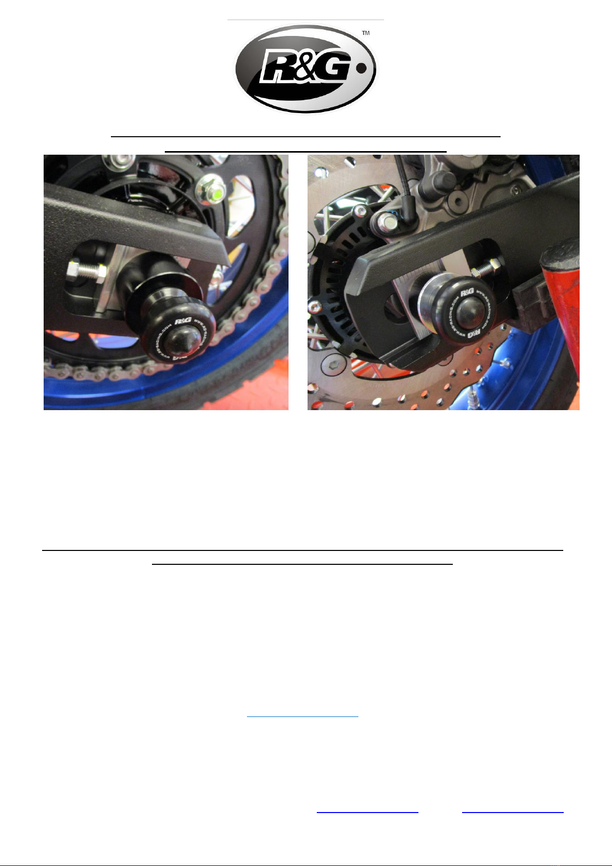
•Nicht überziehen –die selbstsichernden Muttern halten das fest, und montieren Sie die
Abdeckungen für die Muttern (Artikel 1) wie in den Abbildungen A und B abgebildet.
•Überprüfen Sie regelmäßig die Festigkeit der Muttern (z.B. beim Putzen, nachdem Sie mit
Motorrad gefahren sind).
AUSGABE 1 - 11/12/2019 (NSY)
Table of contents
Languages:
Other R&G Motorcycle Accessories manuals
Popular Motorcycle Accessories manuals by other brands

Ohlins
Ohlins FGR 156 Mounting instructions

Corbin
Corbin H-FURY-FLIP quick start guide

GIVI
GIVI E175 Mounting instructions

Volt Resistance
Volt Resistance 12V Instruction booklet

Elektronik Sachse
Elektronik Sachse ZDG 3.23 installation manual

hepco & becker
hepco & becker SOLID 5089529 00 01 quick start guide