ABB Emax 2 Retrofill Product manual

- General Electric AKD-10 Low Voltage Switchgear is a free-standing assembly of metal enclosed
power circuit breakers. It may also be a part of a single-ended or double-ended load center unit
substation.
- It uses WavePro type ANSI Low Voltage Power Circuit Breakers. This manual applies to both
Emax 2 Retrofill breakers for AKD-10 switchgear and OEM substructures.
Installation and maintenance guide
Emax 2 Retrofill Circuit Breakers
Direct Replacement Replacing legacy
GE WaveProTM 800A - 5000A,WavePro
integrally fused 800A -1600A Circuit
Breakers used in AKD-10 & Substructures
Emax 2 Retrofill Circuit Breakers
Installation and maintenance guide

FUSED RETROFILL BREAKER ............................71
39 - Fuse size and mounting ................................................................71
40 - Special 2500A Fuse for WPF-16 ...................................................72
OPEN FUSE LOCKOUT DEVICE .........................75
C

The following important highlighted information appears throughout this document to warn
of potential hazards or to call attention to information that clarifies a procedure. Carefully
read all instructions and become familiar with the devices before trying to install,
operate, service, or maintain this equipment.
This indicates a hazardous situation which, if not avoided, results in death or serious injury.
A variety of electrical hazards warnings are displayed here and are applied to installation
manuals. These are standard or generic alerts and labels that must be taken quite seriously
when installing Retrofill circuit breakers in GE & OEM switchgear and when working with
potentially dangerous electrical equipment (Table 1).
This indicates a hazardous situation, which, if not avoided, would result in death or serious
injury. A variety of electrical hazards warnings are displayed here and are applied to
installation manuals. These are standard or generic alerts and labels that must be taken
quite seriously when installing Retrofill circuit breakers in GE & OEM switchgear and when
working equipment that can cause injury, but may not be necessarily fatal (Table 2).
Danger
Table 1
Warning
Table 2
Overview
1 - Hazards
Preface
Generic Danger Alerts
Generic Warning Alerts
C

Table 4
Table 3
Notice or Note
Caution This pertains to a hazard that has a low level of risk, which means that if not avoided, it could
result in minor or moderate injury. It also indicates that failure to comply with instructions
may result in product damage. (Table 3).
This indicates important information in that it aids in job performance, that is, a notice or
note is used to notify practices not related to personal injury (Table 4).
Custom Caution Alerts
Custom Notice Alerts
C

2 - Warranty
3 - Trademarks and Patents
4 - Standards
5 - Document Conventions
This document is based on information available at the time of its publication. While efforts
requirements have been made to ensure accuracy, the information contained herein does
not cover all details or variations in hardware and software, nor does it provide for every
possible contingency in connection with installation, operation, and maintenance.
Features may be described herein that are not present in all hardware and software systems.
ABB Inc USA assumes no obligation of notice to holders of this document with respect to
changes subsequently made. ABB Inc USA makes no representation or warranty, expressed,
implied, or statutory, with respect to, and assumes no responsibility for the accuracy,
completeness, sufficiency, or usefulness of the information contained herein. No warranties
of merchantability or fitness for purpose shall apply.
Contact your local sales office if further information is required concerning any aspect of
Emax 2 Retrofill Circuit Breaker operation or maintenance.
Emax 2 Retrofill
Emax 2 Retrofill TU, Ekip DIP, Ekip Touch, Ekip Hi-Touch, Ekip G Touch, Ekip G Hi-Touch,
Kip Measuring, Ekip Measuring Pro
Emax 2 Retrofill Trip Unit
Emax2
Warranty
requirements
Details
Agency
Certification
Details
Topics and text are divided into primary, secondary, and tertiary paragraph headings.
Standard Number Title
Low-Voltage AC Power Circuit Breakers & switchgears
Low-Voltage Power Circuit Breakers
Low-Voltage AC and DC Power Circuit Breakers Used in
Enclosures
ANSI C37.13,16,17,20.1,50,51,59
NEMA SG 3,5
NEMA AB1
UL 1066
C

6 - Related Publications
7 - Service and Support
8 - Estimated Time to Complete Tasks
Service and support are available from ABB Inc USA.
Email: [email protected]
Phone: 888-385-1221
Verify the secondary disconnects and match the switchgear cublicle which may take up to
1Hr depending on the complexity of the original breaker. Once the retrofill breaker is fully
prepared, it should take about 20 minutes to swap out the old breaker and rack in the new
Emax 2 Retrofill circuit breaker if the proper lifting bar and hoist are available, it may take an
additional 30 min to replace the door.
The Emax 2 Retrofill, when ordered with 4 wire ground fault, will be equipped with a Neutral
CT adapter. The adapter will modify the GE MicroVersaTrip type Neutral CT output to a
Rogowski sensor output compatible with the Emax 2 Retrofill Trip Unit. With this device, it
will not be necessary to change the neutral CT in the switchgear to a Rogowski sensor.
Title
Publication Publication Number
Accessory: Neutral CT Adapters Installation Instructions
Accessory: Programmer Disconnects Installation Instructions
Accessory: Primary Disconnects Installation Instructions
Accessory: Secondary Disconnects, Installation Instructions
E2.2, 4.2, 6.2 Breakers Installation, Operation & Maintenance Manual
Instructions for using Ekip touch protection releases & accessories
Emax 2 Family Trip units Engineering manual
Installation Manual AKD 10
Installation Manual AKD 8
Installation Manual AKD 6
Installation Manual AKD 5
Accessory: Door Interlock (Door Interlock Kit)
Accessory: Kirk Key installation Manual
Accessory Retrofill Direct Replacement / CiC Full Door Kits AKD-5, 6, 8 & 10
Accessory Retrofill Direct Replacement / CiC Door AdaptorsKits AKD-5, 6, 8 &10
Accessory OEM Direct Replacement Adaptor kits AKD8 & 10
Accessory OEM Direct Replacement Adaptor kits, AKD8 &10, AKR 75/100, B&F TYPE
Accessory OEM Direct Replacement Adaptor kits, AKD8 &10, only for AKR30S
Accessory: Position Switch Plate, Assembly & Wiring
Accessory: Neutral CT Adapters Installation Instructions
Accessory: Programmer Disconnects Installation Instructions
Accessory: Primary Disconnects Installation Instructions
Accessory: Secondary Disconnects, Installation Instructions
E2.2, 4.2, 6.2 Breakers Installation, Operation & Maintenance Manual
Instructions for using Ekip touch protection releases & accessories
Emax 2 Family Trip units Engineering manual
2TSA451010P0000
2TSA451009P0000
2TSA451014P0000
2TSA451011P0000
2TSA451017P0000
2TSA451013P0000
2TSA451007P0000
2TSA451008P0000
2TSA431967R1000
2TSA431968R1000
2TSA431996R1000
2TSA451019P0000
2TSA451018P0000
2TSA451012P0000
2TSA451015P0000
2TSA451016P0000
1SDH001000R0002
1SDH001316R0002
1SDH001330R0002
C

Views
Figure 1
Weight (lbs)
9 - Product Specs
AKD-10 Low Voltage Switchgear is a free-standing assembly of metal-enclosed units of
power circuit breakers and other auxiliary power circuit protective devices. It may also bea
part of a single-ended or double-ended load center unit substation. The AKD-10 Emax 2
Retrofill breaker is defined as a draw-out breaker. With least modifications to be made to
existing switchgear, Emax 2 Retrofill breakers are cost effective solution to upgrade the
existing electrical system. Direct Replacement is the solution where the legacy WavePro
circuit breaker is removed and a new circuit breaker is provided, which racks into the existing
Switchgear Compartment. The direct replacement retrofitting kit allows a reliable upgrade
of the old GE legacy breakers to new Emax 2 Retrofill Breakers.
Below figures (front and back views with finger clusters) present Emax 2 Retrofill breakers,
Which can replace WavePro breakers.
AKD-10 800A to 2000A WPX-08, WPS-16, WPH-16 & WPS-20 Front View
Table to change
C

Figure 2
Figure 3
Figure 4
AKD-10 800A to 2000A WPX-08, WPS-16, WPH-16 & WPS-20 Back View Primary Finger Clusters
AKD: 10 800A WPS- 08 & WPH-08 Front View Primary Finger Clusters
AKD-10 3200A WPS-32, WPH 32 , WPX-32, , WPS-40 & WPX- 40 Front view
C

Figure 5 & 6
Figure 7
Figure 8
AKD-10 3200A WPS-32, WPH-32 & WPX32 Back view AKD-10 4000A WPS-40 & WPX-40 Back View
AKD-10 5000A WPS-50 & WPX-50 Front View
AKD-10 5000A WPS-50 & WPX-50 Back View
Emax 2 Retrofill Circuit Breaker is suitable for application on power systems up to 635 VAC
50/60 Hz.
C

History and Types
10 - History of AKD
AK - Power Circuit Breaker Equipment
D - Drawout circuit breaker construction
Manufactured from 1951 to 1975, all bolted, copper bus design, all drawout breakers AK- 1,2,3,-15 /25 /
50 /75 / 100; the 4000A-max bus rating. Breakers had a ratcheting drawout mechanism, with an
open-door drawout. Breakers were painted ANSI61, light gray,manufactured in Philadelphia
from 1951 to the mid-60s and in Burlington, lowa from the mid-60s to 1975.
The breaker compartment was a welded assembly, and the equipment frame was bolted.
Breaker boxes were stacked to make a vertical section with equipment frame around the
breaker boxes. There were no bus compartment barriers, just an open bus design. Ring
silver-plating was applied to bolted connections.
AKD - 5 Manufactured from 1960 until 1977, the aluminum bus had copper that was “flash-butt
welded’ to the aluminum at bolted connections. During that time, AK-2A, 3A -25 / 50 /T50/75 / 100
(“A” signifies AKD-5 drawout) were produced. Breakers up to 2000A had primary finger
clusters. 3000 & 4000A breakers had a circular primary finger cluster arrangement in
the switchgear compartment. Pull-lanyard drawout mechanism in the switchgear on early
designs was replaced by a single jackscrew mechanism and then later replaced by a double
jack-screw mechanism. Featured is a closed-door, drawout with inner house breaker compartment,
where door moves with the breaker as it is racked in or out. Two bus levels are available with a ring
bus used at 4000A. Particulars include: welded/riveted frame, bus compartment barriers,
line/load separation barriers on mains and ties, isolation barriers on transformer transitions,
copper runbacks on feeder breakers, ring silver-plating on copper, and aluminum bus un-
plated (welded connections). The switchgear is painted sand-gray (beige), with some
instrument doors painted blue. AKR-30/50 in 22"-wide sections were introduced in AKD-5
construction, early 70s. AK25s and AK50s were also available as substructure kits for OEMs to
build around customer gear.
Note: All legacy AK & AKR breakers have a draw out letter code “A”.
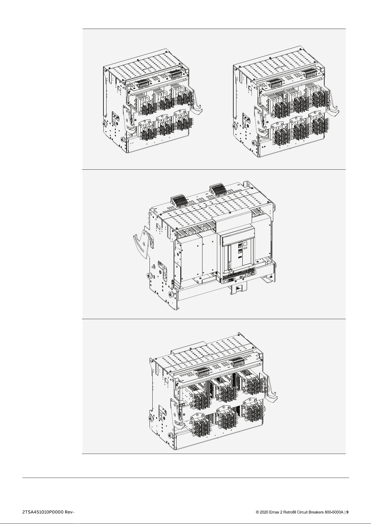
AKD-6 was manufactured in Salisbury, NC from 1977 to 1981. Some AKD-5s, which were built
in Salisbury from 1975 until 1977, got name-plated as AKD-6. There is no “flash-butt” welded
aluminum to copper. Aluminum bus is tin-plated and bolted at shipping splits (but welded
everywhere else). Copper bus design has ring silver plating at bolted joints. AKR-75 / 100s
were introduced during this time. Stab-and-finger connections on 3200A and 4000A
breakers were improvements, versus the round the primary disconnects on the AKD-5, The
4000A breaker was also narrowed to same width and phase-phase spacing as the 3200A.
The AKD-6 uses inner-house drawout breaker compartments on the 800 - 2000A breaker
compartments. They are painted ANSI 61 light gray and breakers have ECS or SST trip units.
AKD-6 should mark a shift away from all AK breakers and to AKR breakers. The AKR-
30/50/50H/T50 breakers used in AKD6 have a shallow 1” steel front escutcheon are drawout
letter code “A” i.e. AKR-4A-30. The AKR-30/50/50H/T50/75/100 breakers sold to OEMs for
their switchgear have a 5” deep plastic front escutcheon & spring loaded sliding “picture
frame”.
These are draw out letter code “B” i.e. AKR-4B-30.The AKR-75/100 breakers used in AKD-6
have a shallow 1” steel front escutcheon and vertical primary fingers. They are drawout letter
code”C” i.e. AKR-4C-75.
AKD - 6
C

AKD - 8
AKD - 10
The AKD-8 was manufactured in Salisbury, NC from 1980 to 1984 and in Burlington, lowa from
1984 to 1999. It was mostly replaced by AKD-10 in 1999 to 2000 but was available thru 2015.
Model 1 and 2 have extruded vertical bus. Model 2 was introduced in 1983 to accommodate revised wire
harness routing. Model 3 was introduced in 1991, using a flat bar vertical bus. AKR breakers use Micro
VersaTrip 9, MVT RMS9, EPIC, MVT Plus, MVT PM or EntelliGuard TU.Aluminum bus was removed
from the design in 1996 in favor of the standard tin-plated copper bus (silver plated optional).
The AKR-30/50/50H/T50 breakers used in AKD8 have 5” deep plastic front escutcheon &
spring loaded sliding “picture frame”. They are drawout letter code “D” i.e. AKR-7D-30. In
AKD-8, most 800-2000A breakers are “feeder” breakers with vertical lower stud & primary
disconnect fingers clusters, but 800-2000A breakers designated as “Main” breakers, have horizontal
lower finger clusters, which is the same as “D” letter code breakers sold to OEM's. A lower
stud rejection bracket differentiates between lower stud orientations.
AKR-75/100/125 circuit breakers used in AKD-8 switchgear have a 5” deep plastic front
escutcheon & spring loaded sliding “picture frame” similar to the small frame breakers.
The positions DISC/TEST/CONN are shown on the side of the front escutcheon by
position of the sliding “picture frame”. The GE AKD-8 breakers have a drawout letter
code “D”. OEM versions are drawout letter code “B” and GE Switchboard versions are
drawout letter code “FP”, “B” & “F” breakers only differed by appearance items. All
Primary disconnect stabs are vertically oriented.
The AKR-125 is a 5000A breaker that had (2) cooling fans. It was release in 1995. None of the
Emax 2 Retrofill breakers utilize fans except for 4000A rating only.
AKD-10 was manufactured in Burlington, IA from 1999 thru 2015. The switchgear
compartment sizes and main & vertical bus arrangements are the same as AKD-8 Model 3.
The compartments have pull-out rails. AKD-10 uses WavePro * drawout-only style breakers.
All breakers have 4 rollers which align with the compartment rails.
The secondary control wiring for all functions is connected thru either one or two 36 point
secondary disconnects with gold plated contacts. Secondary control wiring terminates at
fixed standard locations on the 36 point disconnects. Each breaker has a pump style manual
charging handle and manual push OPEN and Push CLOSE buttons. The front escutcheon is
5” deep with a sliding picture frame, but is wide enough so the trip unit and new style bell
alarm are visible thru the front door of the switchgear.
Note GE Switchboard plants initially shipped “WS” style breakers and later shifted to “WE”
style breakers to be consistent with GE Switchgear from Burlington, lowa. The 5000A
breaker had cooling fans. None of the Emax 2 Retrofill breakers utilize fans except the 4000A
fully rated breaker.
(W1 & We Catalog numbers on legacy WavePro breakers designate additional dead front
shields)
C

Figure 11
Figure 10
Figure 9 AKD-10, 800A Retrofill Breaker Dimensions (WPS-08, WPH-08)
AKD-10, 800-2000A Retrofill Breaker Dimensions (WPX-08, WPS-16, WPH-16, WPS-20)
AKD-10, 3200A Retrofill Breaker Dimensions (WPS-32, WPH-32, WPX-32)
The following engineering or assembly drawings describe the layout and dimensions of the
AKD-10 Retrofill breaker.
AKD-10: Retrofill Breaker
11 - AKD -10 :Mechanical Drawings
C

Figure 12
Figure 13
AKD-10, 4000A with forced cooling (w/fans) Retrofill Breaker Dimensions (WPS-40, WPX-40)
Forced cooling (w/Fans) for
4000A Rating Only.
Fans Turn ON at 3600A and
OFF at 3400A.
For other detail related to
Trip unit config and wiring
refer to Fan control section
Breakers ordered with a 3600A Rating plug for max 90% load do not require fans.
AKD-10, 5000A Retrofill Breaker Dimensions (WPS-50, WPX-50)
The legacy WavePro 5000A breaker was equipped with fans. The Emax 2 5000A retrofill does NOT require fans.
C

Figure 14
Figure 15
AKD-10: Empty Compartment with Shutters
NOTE: Section width 22”-800-2000A
AKD-10: Empty Compartment with Racks/Rails Extended
12 - Interior View
AKD-10 : Compartment
The figures below present a new AKD-10 compartment, with one photo showing the rails
extended.
C

13 - Interior Components
14 - Interior View
Figure 17
Figure 16
The figures below present a new AKD-10 compartment, with one photo showing the rails
extended.
All 800, 1600, 2000
compartments See
“Modify AKD-10
Switchgear
Compartment”
Once spacer Blocks are a
added behind
Secondary disconnects
the Legacy WavePro
circuit breakers must
not be installed
AKD-10, Circuit Breaker Compartment for Wave Pro breakers
Major components of an AKD-10 compartment.
AKD-10, Empty Compartment
NOTE: Section width 30”-3200-4000A; 38”-5000A
C

AKD-10, Empty Compartment with Racks/Rails Extended
Figure 18
Figure 19
15 - Interior Components
AKD-10, Circuit Breaker Compartment for WPS-32/WPH-32/WPX-32/WPS-40/WPX-40/WPS-50/WPX-50
Breakers
Major components of an AKD-10 compartment.
C

lt must be ensured that the supply power to the
Shack and Saad compartment is turned off/
compartment is denergized for all the incoming
and outgoingcircuits of the LVS prior to any work
being conducted on it.
During the installation and related work on the
equipment, it must be ensured that the operator
is using the prescribed PPE for the specified
tasks
Ensure only qualified personnel install, operate, service, and maintain all electrical
equipment.
Danger
16 - Cut Power to AKD-10 Switchgear
Modify AKD-10 , Switchgear Compartment
Before modifying the switchgear compartment, de-energize/switch off the breaker. If the
circuit breaker is ON and the springs are charged, to turn it off, press the OPEN button on the circuit
breaker fascia, and ensure that the circuit breaker contacts are open.
To rack-out legacy old breaker from compartment, refer to your legacybreaker’s manual on
how to remove the existing breaker.
17 - Rack Out AKD-10 Legacy/Existing CB
18 - Check,Clean,Grease AKD-10 Compartment
Inspect the compartment for damage or signs of overheating.
Check the orientation of primary finger clusters match the switchgear stabs.
Check racking pin diameters agree with breaker racking cam slots (AKD-10 has a
large diameter pin and cam slot on right side).
Check the secondary disconnect integrity & their mounting supports for any damage
or cracks .
If switchgear parts show cracks or damage contact ABB post sales service 888-437-
3765.
Check each breaker compartment for bolted joints in the primary disconnect bars.
Where such joints exist, check the bolts for tightness.
Inside the compartment, check the contact areas on each primary disconnect bar for
foreign matter that may have accumulated. Clean those areas if necessary with a
clean, lint-free rag and isopropyl alcohol or acetone.
Be sure to apply a thin film of red Mobilgrease 28 to the primary disconnect contact
areas for better electrical connections inside the compartment.
C

19 - Install Secondary Disconnect Spacer Block (800A-2000A ONLY)
20 - Quality
21 - Information Label
On the front of each circuit breaker there is a factory-assembled label that details all electrical
accessories included on the circuit breaker.
All Emax 2 Retrofill circuit breakers have been designed and manufactured to ANSI standards.
The design was based on the original requirements of the legacy switchgear and breaker.
The product is manufactured in ABB Inc USA, Senatobia, Missisipi (MS) and is inspected using some
of the same master gauges used on the legacy WavePro breakers to confirm electrical and
mechanical performance, including rejection-features.
Install the spacer block provided as shown in Figure 20, below. Remove the protective tape
on the block and stick it on the secondary disconnect mounting plate as shown in Figure 20.
Be sure the spring is moved to the front of the spacer block.
Optional: The hole in the spacer block can be used to add a #10-32 screw, 34” inch long.
Drill a 0.177"(4.5mm) hole in the steel plate above and install 10-32 taptite thread forming
screw (ABB part: N722P16012B6)
Note: Use a #16 Std (@.177”) or 4.5mm metric drill bit Use 5/16” hex to install screw to 45-50
in-lbs Torque.
AKD-10, Secondary Disconnect Spacer Black (800-2000A ONLY)
Figure 20
C

22 - Product and Catalog Serial Numbers
23 - Remove Circuit Breaker from Container
Product catalog and serial numbers should be kept handy when communicating about the
circuit breaker. Each circuit breaker has a unique serial number (S/N) located on the front
fascia.
1. Inspect the shipping container for obvious signs of rough handling and/or external damage
incurred during transportation.
2. Record any observed damage for reporting to the carrier. Ensure all recorded reports and
claims include the order number and name plate information.
3. Remove the banding straps and lift the top cover.
4. Remove all packaging material.
5. Remove all product documentation and store properly.
6. Unscrew the mounting screws that fasten the circuit breaker to the bottom of the shipping
pallet and remove the circuit breaker.
7, Reverse the orientation of two shipping plates with flanges inward and reinstall on breaker
(3200A, 4000A & 5000A only). These flanges will keep the breaker from resting on the
rejection pins and centering guide pin whenever it is placed on a flat surface.
1. Use a lifting device for moving circuit breaker in order to avoid personal injury and
damaging the breaker.
2. Use a proper overhead lifting device to mount breaker into the switchgear. Contact the
nearest sales office for availability of a hoisting device.
Inspect and
Prepare
Use Lifting Device
C

Turn off all power to switchgear. Tagout and
lockout main source, up-stream or main
breaker.
Failure to comply with these instructions will
result in death or serious injury from severe
burns caused by arc flashing that has
exceedingly high temperatures.
Always wear personal protection equipment
according to OSHA standards and appropriate
to the severity of potential burns.
Ensure only qualified personnel install, operate, service, and maintain all electrical
equipment.
Do not walk or remain under any heavy
assembly while hoisted above head as the
chains securing the assembly may give way.
Ensure lifting equipment has capability for device being lifted.
Wear hard hat, gloves, and safety shoes.
Failure to comply with these instructions could result in serious injury.
PRODUCT DAMAGE
Ensure circuit breaker and its accessories are always
used within their designated ratings.
Do not allow the circuit breaker to hit a hard surface
while handling.
Do not drag or slide the circuit breaker across a hard
or rough surface.
A factory-installed rejection feature prevents mismatching circuit breakers and
cassettes/ substructure, preventing the insertion of a circuit breaker with a lower rating
into a higher rated cassette/substructure, or the insertion of a higher rated
circuit breaker into a lower rated cassette/substructure.
By following the procedures below, you should be able to install the breaker with minimum
effort and time.
Danger
Caution
Notice
Unpack Circuit Breaker
C
This manual suits for next models
4
Table of contents
Other ABB Circuit Breaker manuals
Popular Circuit Breaker manuals by other brands

Leakomatic
Leakomatic M3i+ user manual

CHINT
CHINT YBLX-K3 Mounting instructions

Siemens
Siemens 3VA9 7 0JA1 Series operating instructions

Siemens Energy
Siemens Energy SB ICCB Installing

Vertical Power
Vertical Power VP-X Pro Installation and operating manual

Siemens
Siemens 3VL9600 - 4W 0 Series operating instructions