8
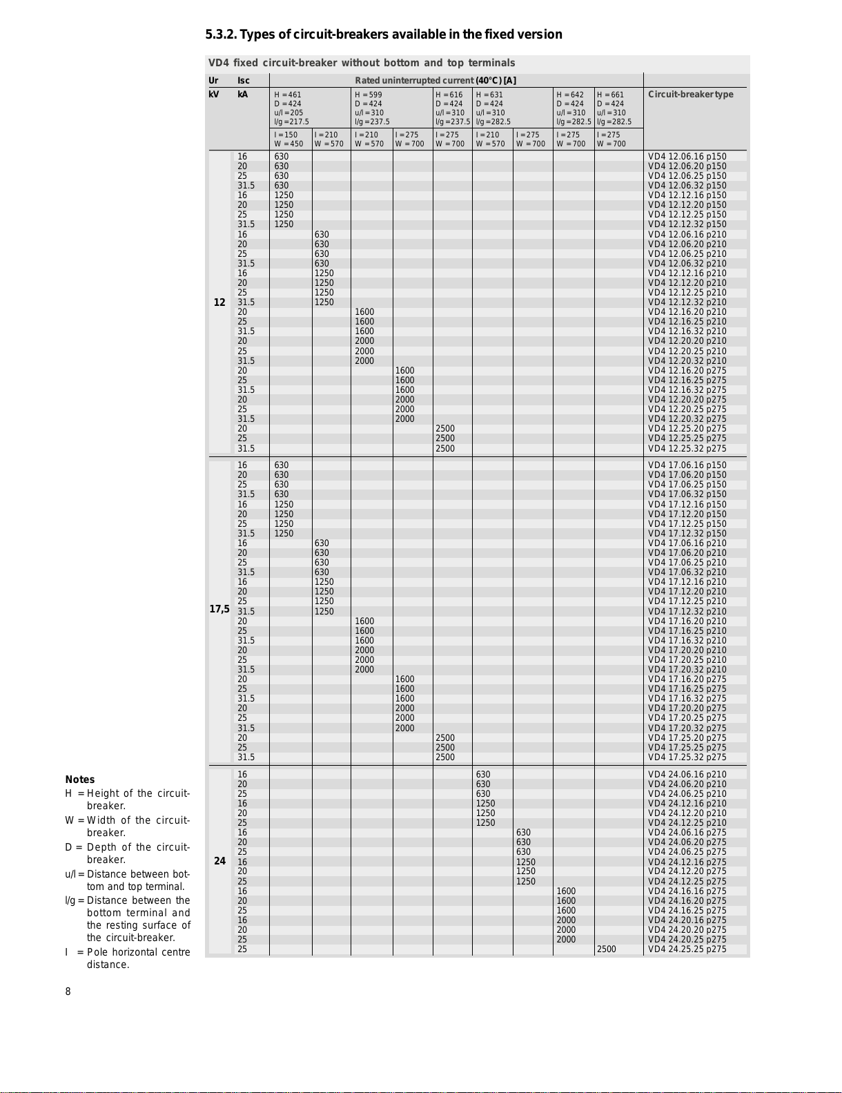
5.3.2. Types of circuit-breakers available in the fixed version
24
VD4 fixed circuit-breaker without bottom and top terminals
17,5
12
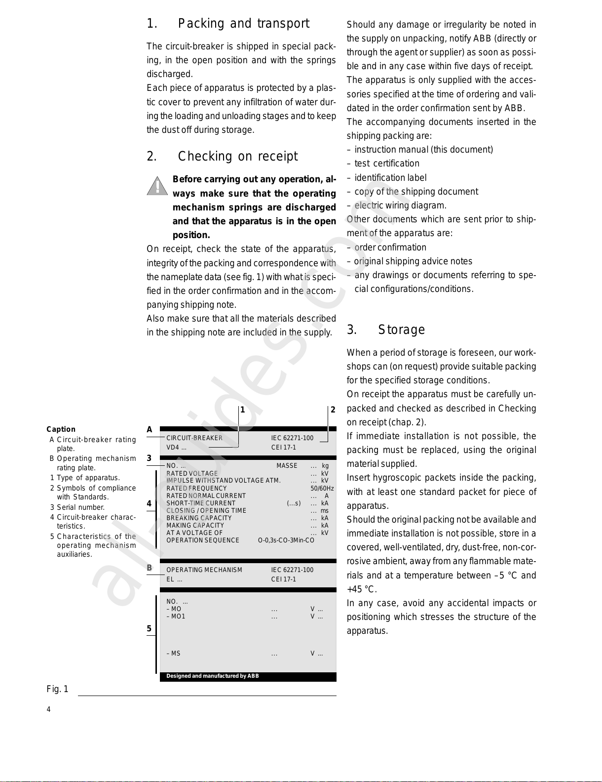
Notes
H = Height of the circuit-
breaker.
W = Width of the circuit-
breaker.
D = Depth of the circuit-
breaker.
u/l= Distance between bot-
tom and top terminal.
l/g= Distance between the
bottom terminal and
the resting surface of
the circuit-breaker.
I = Pole horizontal centre
distance.
Ur Isc Rated uninterrupted current (40°C) [A]
kV kA H = 461 H = 599 H = 616 H = 631 H = 642 H = 661 Circuit-breakertype
D = 424 D = 424 D = 424 D = 424 D = 424 D = 424
u/l=205 u/l=310 u/l=310 u/l= 310 u/l = 310 u/l=310
l/g=217.5 l/g=237.5 l/g=237.5 l/g=282.5 l/g=282.5 l/g=282.5
I = 150 I = 210 I = 210 I = 275 I = 275 I = 210 I = 275 I = 275 I = 275
W = 450 W = 570 W = 570 W = 700 W = 700 W = 570 W = 700 W = 700 W = 700
16 630 VD4 12.06.16 p150
20 630 VD4 12.06.20 p150
25 630 VD4 12.06.25 p150
31.5 630 VD4 12.06.32 p150
16 1250 VD4 12.12.16 p150
20 1250 VD4 12.12.20 p150
25 1250 VD4 12.12.25 p150
31.5 1250 VD4 12.12.32 p150
16 630 VD4 12.06.16 p210
20 630 VD4 12.06.20 p210
25 630 VD4 12.06.25 p210
31.5 630 VD4 12.06.32 p210
16 1250 VD4 12.12.16 p210
20 1250 VD4 12.12.20 p210
25 1250 VD4 12.12.25 p210
31.5 1250 VD4 12.12.32 p210
20 1600 VD4 12.16.20 p210
25 1600 VD4 12.16.25 p210
31.5 1600 VD4 12.16.32 p210
20 2000 VD4 12.20.20 p210
25 2000 VD4 12.20.25 p210
31.5 2000 VD4 12.20.32 p210
20 1600 VD4 12.16.20 p275
25 1600 VD4 12.16.25 p275
31.5 1600 VD4 12.16.32 p275
20 2000 VD4 12.20.20 p275
25 2000 VD4 12.20.25 p275
31.5 2000 VD4 12.20.32 p275
20 2500 VD4 12.25.20 p275
25 2500 VD4 12.25.25 p275
31.5 2500 VD4 12.25.32 p275
16 630 VD4 17.06.16 p150
20 630 VD4 17.06.20 p150
25 630 VD4 17.06.25 p150
31.5 630 VD4 17.06.32 p150
16 1250 VD4 17.12.16 p150
20 1250 VD4 17.12.20 p150
25 1250 VD4 17.12.25 p150
31.5 1250 VD4 17.12.32 p150
16 630 VD4 17.06.16 p210
20 630 VD4 17.06.20 p210
25 630 VD4 17.06.25 p210
31.5 630 VD4 17.06.32 p210
16 1250 VD4 17.12.16 p210
20 1250 VD4 17.12.20 p210
25 1250 VD4 17.12.25 p210
31.5 1250 VD4 17.12.32 p210
20 1600 VD4 17.16.20 p210
25 1600 VD4 17.16.25 p210
31.5 1600 VD4 17.16.32 p210
20 2000 VD4 17.20.20 p210
25 2000 VD4 17.20.25 p210
31.5 2000 VD4 17.20.32 p210
20 1600 VD4 17.16.20 p275
25 1600 VD4 17.16.25 p275
31.5 1600 VD4 17.16.32 p275
20 2000 VD4 17.20.20 p275
25 2000 VD4 17.20.25 p275
31.5 2000 VD4 17.20.32 p275
20 2500 VD4 17.25.20 p275
25 2500 VD4 17.25.25 p275
31.5 2500 VD4 17.25.32 p275
16 630 VD4 24.06.16 p210
20 630 VD4 24.06.20 p210
25 630 VD4 24.06.25 p210
16 1250 VD4 24.12.16 p210
20 1250 VD4 24.12.20 p210
25 1250 VD4 24.12.25 p210
16 630 VD4 24.06.16 p275
20 630 VD4 24.06.20 p275
25 630 VD4 24.06.25 p275
16 1250 VD4 24.12.16 p275
20 1250 VD4 24.12.20 p275
25 1250 VD4 24.12.25 p275
16 1600 VD4 24.16.16 p275
20 1600 VD4 24.16.20 p275
25 1600 VD4 24.16.25 p275
16 2000 VD4 24.20.16 p275
20 2000 VD4 24.20.20 p275
25 2000 VD4 24.20.25 p275
25 2500 VD4 24.25.25 p275