Sicherheits- und Warnhinweise:
Anlage freischalten!
Vor Installations-, Wartungs- oder Änderungsarbeiten: Anlage spannungsfrei schalten, vor Wiedereinschalten sichern.
Vor Inbetriebnahme:
Achtung! Unsachgemäße Installation/Betrieb kann die Sicherheit beeinträchtigen und zu Betriebsstörungen oder zur Zerstörung des Gerätes führen. Vor der
Inbetriebnahme ist Folgendes sicherzustellen:
• Netzanschluss gemäß den landesspezifischen Vorschriften durchführen
• Zuleitungen und Gerät ausreichend absichern. Eine Trenneinrichtung für das Netzteil vorsehen, um das Gerät und die Zuleitungen im Bedarfsfall zu unterbrechen
• Schutzleiter an die Klemme oanschließen (Schutzklasse I)
• Die Sekundärseite des Netzteils ist nicht geerdet. Sie kann je nach Bedarf (wahlweise L+ oder L-) vom Anwender geerdet werden.
• Ausgangsleitungen für den Ausgangsstrom des Netzteils dimensionieren und polrichtig anschließen.
• Abstände zu benachbarten Geräten beachten um eine ausreichende Kühlung zu gewährleisten
Im Betrieb:
• Keinerlei Änderungen an der Installation (primär- und sekundärseitig) vornehmen! (Starkstrom!). Gefahr von Lichtbögen und elektrischem Schlag (Lebensgefahr!)
• Verbrennungsgefahr: In Abhängigkeit der Betriebsbedingungen kann die Gehäusetemperatur hohe Werte annehmen.
• Die interne Sicherung kann vom Anwender nicht ausgetauscht werden. Löst die interne Sicherung aus, liegt mit hoher Wahrscheinlichkeit ein Gerätedefekt vor.
In diesem Fall ist eine Überprüfung des Netzteiles durch den Hersteller erforderlich.
Achtung: Hochspannung! Gespeicherte Energie! Gefährliche Energie am Ausgang!
In den Netzteilen befinden sich Bauelemente mit hoher gespeicherter Energie und Stromkreise mit Hochspannung! Deshalb keine Gegenstände in das Gerät einfüh-
ren und das Gerät nicht öffnen. Bei einigen Geräten dieser Serie kann der Ausgang gefährlich hohe Energiemengen abgeben. Sicherstellen, dass Bedienpersonal
vor versehentlicher Berührung energieführender Teile geschützt ist.
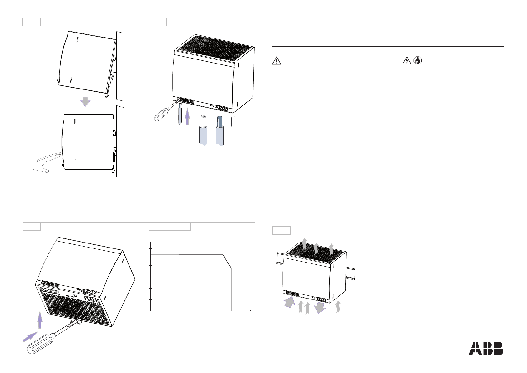
Konvektionskühlung:
Die Lüftungsöffnungen nicht bedecken! Um das Gerät herum genügend Platz zur Kühlung lassen! Siehe Fig. 1
Montage:
1. DIN-Schiene (TH 35-15 oder TH 35-7,5 nach IEC/EN 60715) wie in Abbildung 1 dargestellt auf der Montageplatte befestigen, horizontale Einbaulage, Eingangs-
klemmen unten, auf allen Seiten Mindestabstand von 25 mm zu benachbarten Geräten einhalten.
2. Gerät wie in Abbildung 2 dargestellt auf die DIN-Schiene aufschnappen.
1) Gerät leicht nach oben kippen und auf DIN-Schiene aufsetzen.
2) Bis zum Anschlag nach unten klappen.
3) Unten gegen die Vorderseite drücken, um zu verriegeln. Leicht am Gerät rütteln, um Verriegelung zu überprüfen.
3. Entfernen von der DIN-Schiene wie in Abbildung 4 dargestellt. Isolierten Schraubendreher zur Entriegelung verwenden.
Elektrischer Anschluss (siehe Abbildung 3):
Korrekte Dimensionierung, Abisolierlänge und Anschluss der Kabel sicherstellen.
Frontelemente:
Potentiometer „OUTPUT Adjust“ zum Einstellen der Ausgangsspannung.
Schalter „single/parallel“ zur Einstellung von Einzel- oder Parallelbetrieb.
Schalter „U/I mode/Hiccup mode“ zur Einstellung des Ausgangsverhaltens bei Überlast.
Meldekontakt 13-14 (Halbleiter, max. 60 V DC / 0,3 A): Geschlossen, wenn die Ausgangsspannung größer als 19,4 V ist (nur bei 24 V-Geräten).
Typ grüne LED „OK“: An grüne LED „OK“: Aus rote LED „LOW“: An rote LED „LOW“: Aus
CP-T 24/20.0 M18,92 V m 18,83 V M2,92 V M 18,82 V
CP-T 48/10.0 M38,03 V m 38,01 V M2,85 V M 37,97 V
Externer Eingangsschutz:
Die Auswahl des externen Schutzelementes muss nach den geltenden nationalen Vorschriften erfolgen. Es ist auch die Spannung zu beachten!
Empfohlener Leitungsschutzschalter, z.B. bei 3 x 400 V, ABB-Type S203-xxB (B-Characteristic) oder S203-xxC (C-Characteristic) mit Nennströmen bis max. 20 A
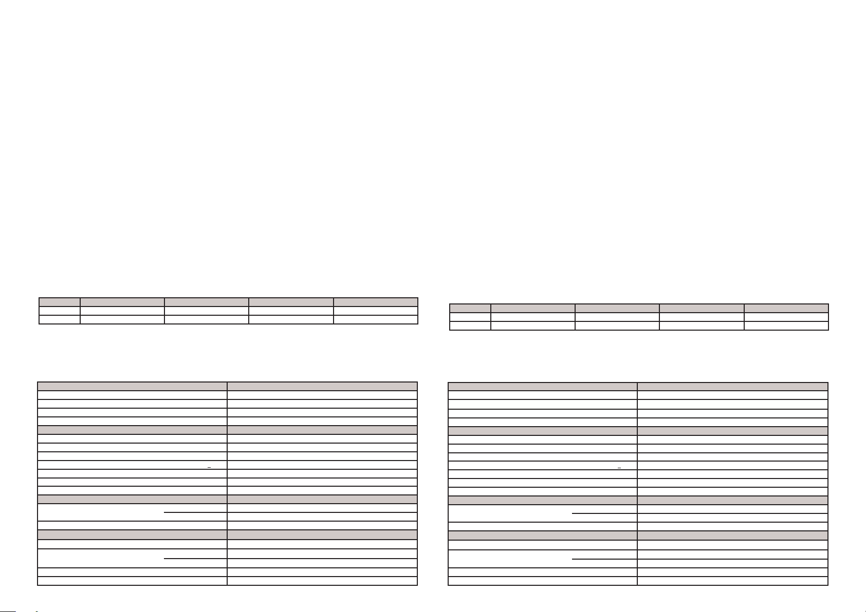
Technische Daten:
Daten bei Tu = 25 °C und Bemessungswerten, sofern nichts anderes angegeben ist.
Safety instructions and warnings:
Disconnect system from supply network!
Before any installation, maintenance or modification work: Disconnect the system from the supply network and protect against switching on.
Before start of operation:
Attention! Improper installation/operation may impair safety and cause operational difficulties or destruction of the unit. Before operation the following must be
ensured:
• Connect to main according to the specific national regulations.
• Power supply cables and unit must be sufficiently fused. A disconnecting device has to be provided for the end product to disengage unit and supply cables
from supply mains if required.
• The protective earth conductor must be connected to the terminal o(Protection class I)
• The secondary side of the power supply unit is not earthed and can be earthed by the user according to the needs with L+ or L-.
• Rate the output lines for the output current of the power supply and connect them with the correct polarity.
• In order to ensure sufficient air-cooling the distance to other devices has to be considered.
In operation:
• Do not modify the installation (primary and secondary side)! High current! Risk of electric arcs and electric shocks (danger to life)!
• Risk of burns: Depending on the operation conditions the enclosure can become very hot.
• The internal fuse is not user-replaceable. If the internal fuse blows, most probably the device is defective. In this case, an examination of the switch mode power
supply by the manufacturer is necessary.
Warning: High voltage! Stored energy! Energy hazard at output!
The power supplies contain components with high stored energy and circuits with high voltage! Do not introduce any objects into the unit, and do not open the unit.
With some units of this range the output is capable of providing hazardous energy. Ensure that the service personnel is protected against inadvertent contact with
parts carrying energy.
Convection cooling:
Do not cover any ventilation holes! Leave sufficient space around the unit for cooling! See Fig. 1
Mounting:
1. Fasten the DIN rail (TH 35-15 or TH 35-7,5 according to IEC/EN 60715) as shown in Fig. 1 on the mounting plate, horizontal mounting position, input terminals on
bottom, respect on all sides the minimum distance of 25 mm to other units.
2. Snap on DIN rail as shown in Fig. 2
1) Tilt the unit slightly upwards and fit the unit on the DIN rail
2) Lift it downward until it hits the stop
3) Press against the bottom front side for locking. Shake the unit slightly to check the locking
3. Remove the unit from the DIN rail as shown in Fig. 4. Use an insulated screwdriver for the unlocking.
Electrical connection (see Fig. 3):
Ensure correct dimensioning, stripping length and connection of the cables.
Front elements:
Potentiometer „OUTPUT Adjust“ for the adjustment of the output voltage.
Switch „single/parallel“ for selection of single or parallel operation.
Switch „„U/I mode/Hiccup mode“ for selection of the output behavior in case of an overload.
Signalling contact 13-14 (solid-state, max. 60 V DC / 0.3 A) is ON when the output voltage is higher than 19.4 V (on 24 V devices only).
Type green LED „OK“: ON green LED „OK“: OFF red LED „LOW“: ON red LED „LOW“: OFF
CP-T 24/20.0 M18.92 V m 18.83 V M2.92 V M 18.82 V
CP-T 48/10.0 M38.03 V m 38.01 V M2.85 V M 37.97 V
External input protection:
Observe the national regulations when selecting the external circuit breaker. Voltage also to be considered!
Recommended line protection device, e.g. with 3 x 400 V, ABB type S203-xxB (B-characteristic) or S203-xxC (C-characteristic) with rated currents of max. 20 A.
Technical data:
Data at Ta = 25 °C and rated values, unless otherwise indicated.
Input circuit CP-T 24/20.0 and CP-T 48/10.0
Rated input voltage 3 x 400-500 V AC
Input voltage range 340-575 V AC / 480-820 V DC
Frequency range 47-63 Hz
Internal input fuse 3.15 A slow-acting / 500 V AC / phase
Output circuit
Rated output voltage / power see rating label
Tolerance of the output voltage 0...+1 %
Adjustment range of the output voltage see rating label
Derating of the output current 60 °C < Ta< 70 °C see Fig. 5
Characteristic curve of output configurable, U/I characteristic curve or hiccup mode
Open-circuit protection continuous open-circuit proof
Parallel connection in order to increase power configurable, 2 devices, min. 0.1 Ir- max. 0.9 Ir
Isolation data
Rated insulation voltage input / output circuit 3 kV AC
input circut / PE 1.5 kV AC
Pollution degree 2
General data
Degree of protection housing / terminals IP20 / IP20
Ambient temperature ranges Taoperation / storage -30...+70 °C (-22...158 °F) / -40...+85 °C (-40...185 °F)
rated load -30...+60 °C (-22...140 °F)
Altitude during operation IEC/EN 60068-2-13 max. 5000 m
Dimensions (WxHxD) 150 x 131 x 118.8 mm (5.91 x 5.16 x 4.68 in)
Eingangskreis CP-T 24/20.0 und CP-T 48/10.0
Bemessungseingangsspannung 3 x 400-500 V AC
Eingangsspannungsbereich 340-575 V AC / 480-820 V DC
Frequenzbereich 47-63 Hz
Interne Eingangssicherung 3.15 A träge / 500 V AC / Phase
Ausgangskreis
Bemessungsausgangsspannung / -leistung siehe Leistungsschild
Toleranz der Ausgangsspannung 0...+1 %
Einstellbereich der Ausgangsspannung siehe Leistungsschild
Derating des Ausgangsstromes 60 °C < Tu< 70 °C siehe Fig. 5
Ausgangskennlinie konfigurierbar, Hiccup-Modus oder U/I Kennlinie
Leerlaufschutz dauerleerlauffest
Parallelschaltbarkeit zur Leistungserhöhung konfigurierbar, 2 Geräte, min. 0,1 Ir- max. 0,9 Ir
Isolationsdaten
Bemessungsisolationsspannung Ein-/ Ausgangskreis 3 kV AC
Eingangskreis / PE 1,5 kV AC
Verschmutzungsgrad 2
Allgemeine Daten
Schutzart Gehäuse / Klemmen IP20 / IP20
Umgebungstemperaturbereiche TuBetrieb / Lagerung -30...+70 °C (-22...158 °F) / -40...+85 °C (-40...185 °F)
Bemessungslast -30...+60 °C (-22...140 °F)
Betriebshöhe IEC/EN 60068-2-13 max. 5000 m
Abmessungen (BxHxT) 150 x 131 x 118,8 mm (5,91 x 5,16 x 4,68 in)