ABB RPB 520 User manual

Instruction manual
505 890-102
2003-05
RPB 320/420/520 Power source

The information in this document can be subject to change without prior notice and should not be
regarded as an undertaking from ABB. ABB assumes no responsibility for errors that can appear in
this document.
ABB is not responsible for damage incurred by the use of this document or software or hardware
described in this document.
The document, or parts there of, may not be reproduced or copied without prior permission from ABB.
It may neither be imparted to a third party nor otherwise used without authorisation. Infringement here
of will be subject to action in accordance with applicable laws.
Further copies of this document can be obtained from ABB at current prices.
ABB Automation Technology Products AB
Article number: 505 890-102
Date: 2003-05
ABB Automation Technology Products AB
Arc Welding & Application Equipment
S-695 82 Laxå
Sweden

RPB 320/420/520
LIST OF CONTENTS Page
505 890-102 3
1 Introduction................................................................................................................. 5
1.1 Safety ................................................................................................................. 5
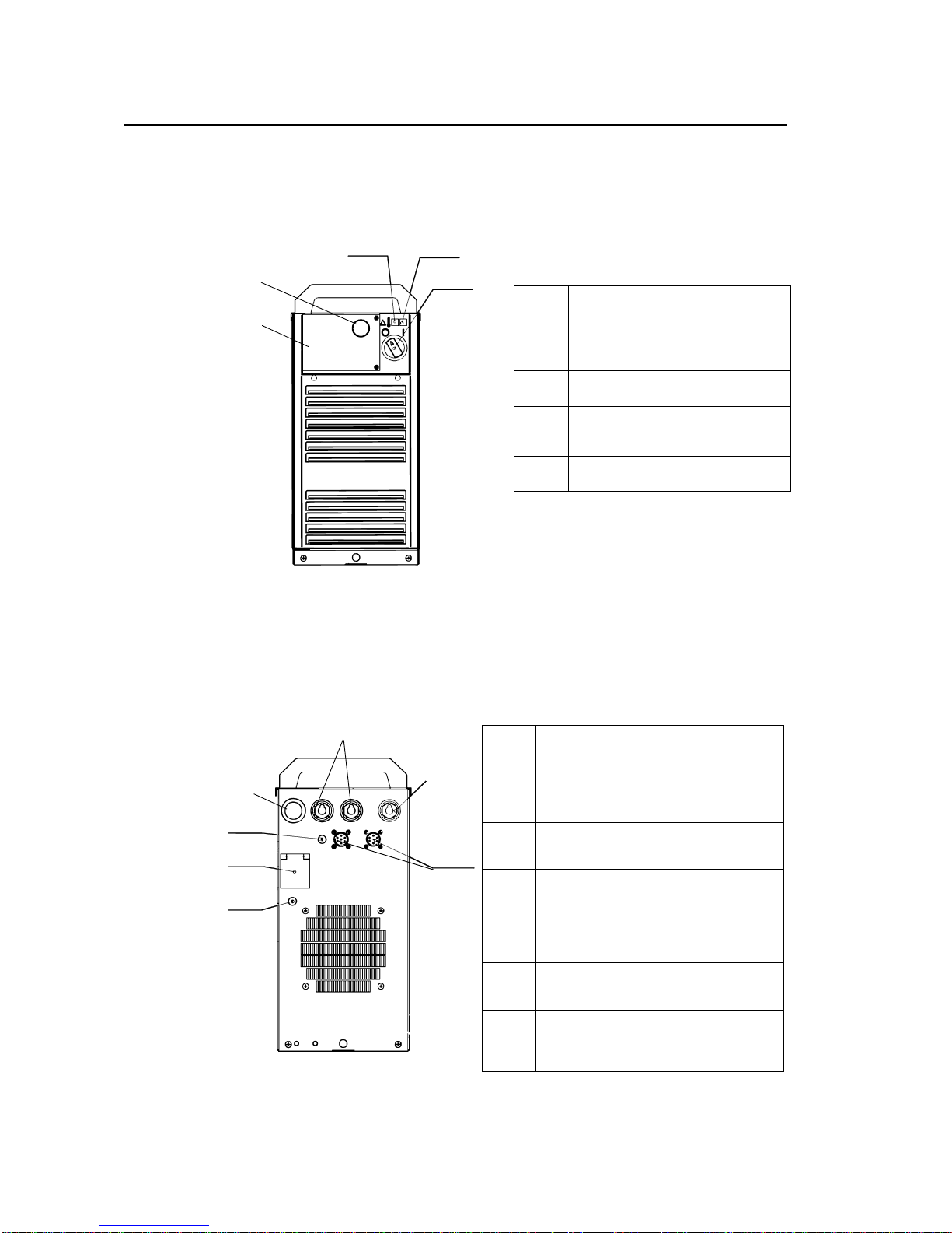
1.2 Description......................................................................................................... 6
2 Start-up ........................................................................................................................ 7
2.1 Placing ............................................................................................................... 7
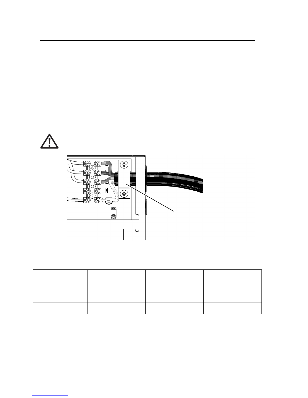
2.2 Connection to the mains .................................................................................... 8
3 Controls and utilization.............................................................................................. 9
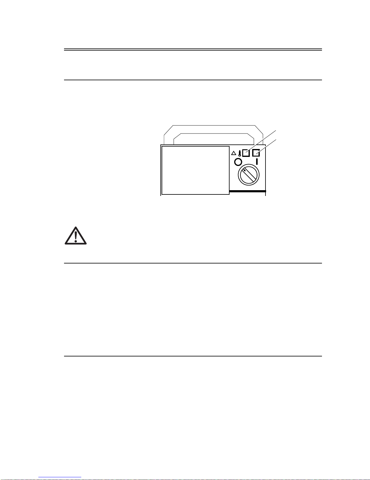
3.1 Main switch ON/OFF (I/O) ............................................................................... 9
3.2 Indicating lamps................................................................................................. 9
3.3 The function of the fan....................................................................................... 9
4 Maintenance/Service................................................................................................... 11
4.1 Cables................................................................................................................. 11
4.2 Power source...................................................................................................... 11
4.3 Functional trouble.............................................................................................. 12
5 Technical Data ............................................................................................................. 15
6 Diagram........................................................................................................................17
6.1 RPB 320............................................................................................................. 17
6.2 RPB 420............................................................................................................. 18
6.3 RPB 520............................................................................................................. 19
7 Reservdelsförteckning/Spare Parts List..................................................................... 21
7.1 RPB 320............................................................................................................. 22
7.2 RPB 420............................................................................................................. 26
7.3 RPB 520............................................................................................................. 30

RPB 320/420/520
4505 890-102

53%
,QWURGXFWLRQ
505 890-102 5
,QWURGXFWLRQ
This manual is intended for use by technicians with appropriate electrical training
for fault-tracing and repair.
The product complies with the demands for CE marking.
6DIHW\
0DQ\FRPSRQHQWVLQWKLVSRZHUVRXUFHDUHFRQQHFWHGWRPDLQVYROWDJHSRWHQ
WLDO
:$ 5 1 , 1
$UFZHOGLQJDQGFXWWLQJFDQEHLQMXULRXVWR\RXUVHOIDQGRWKHUV7DNHSUHFDX
WLRQVZKHQZHOGLQJ$VNIRU\RXUHPSOR\HU¶VVDIHW\SUDFWLFHVZKLFKVKRXOGEH
EDVHGRQPDQXIDFWXUHV¶VKD]DUGGDWD
(OHFWULFVKRFN&DQNLOO
• Install and earth the welding equipment in accordance with applicable
standards.
• Do not touch live electrical parts or electrodes with bare hands, wet gloves
or wet protecting clothing.
• Insulate yourself from earth and from the workpiece.
• Ensure your working stance is safe.
)XPHVDQGJDVHV&DQEHGDQJHURXVWRKHDOWK
• Keep your head out of the fumes.
• Use ventilation, extraction at the arc, or both, to keep fumes and gases from
your breathing zone and the general area.
$UFUD\V&DQLQMXUHH\HVDQGEXUQVNLQ
• Protect your eyes and body. Use the correct welding screen and filter lens
and wear protecting clothing.
• Protect bystanders with suitable welding helmets or curtains.
)LUHKD]DUG
• Sparks (spatter) can cause fire. Make sure that there are no inflammable
materials nearby.
0DOIXQFWLRQ&DOOIRUH[SHUWDVVLVWDQFH

53%
,QWURGXFWLRQ
6505 890-102
'HVFULSWLRQ
)URQWSDQHO
)LJXUH3RZHUVRXUFHRPB 320IURQW
5HDUSDQHO
)LJXUH3RZHUVRXUFHRPB 320UHDUSDQHO
S11 Main switch I/O
02 Mounting opening for
control panel
H11 Indicating lamp I/O
H12 Indicating lamp for ther-
mal protection
5Welding dynamics control
01 Mains cable grommet
F11 Fuse for control panel 6.3 A, Slow
F12 Fuse for mains terminal 1,0 A Slow
X11 Welding and return cable
connection Parallel
X12 Welding and return cable
connection Parallel
X13 Welding and return cable
connection
X14
X15 Control cable connection Parallel
X16 By productive earhed outlet
isolated safety transformer,
RPB 420/520
1~”230V/
250VA”
02
H11H12
S11
5
01
F11
F12
X16
X11, X12
X14
X15
X13

53%
6WDUWXS
505 890-102 7
6WDUWXS
3ODFLQJ
3ODFHWKHSRZHUVRXUFHRQDVWHDG\KRUL]RQWDOGU\DQGGXVWIUHHIRXQGDWLRQ
)LJXUHPD[°, (&(1
• Preferably place the machine above floor level.
• Make sure there is DWOHDVW 20 cm free space behind and in front of the
power source for the cooling air to circulate.
• Protect the power source from heavy rain and under hot conditions also
from direct sunlight.
)LJXUH
'HJUHHRISURWHFWLRQRIPDFKLQH,3DOORZVDWLWVPD[LPXPWKHZDWHUVSUD\
FRPLQJLQDQJOHWRKLWPDFKLQH¶VRXWHUFRYHULQJ
See to that the machine is positioned away from line of particle spray, created by
grinding tools etc.
max. 15°
rain water
60°

53%
6WDUWXS
8505 890-102
&RQQHFWLRQWRWKHPDLQV
The power source is supplied with 5 m mains cable without plug.
1RWHMounting or replacing the mains connection cable and plug shall only be exe-
cuted by an expert.
1RWHFor the mounting of the cable, first remove the right-hand side panel.
7REHREVHUYHGZKHQPRXQWLQJWKHPDLQVFDEOH
Pass the cable through the hole on the rear of the power source and lock it by way
of the cable retainer (05). Connect the phase conductor of the cable to the connec-
tions L1, L2 and L3. Connect the yellow/green earth conductor to the connection.
,IDFRQGXFWRUFDEOHLVXVHGWKH]HURFRQGXFWRULVWREHFRQQHFWHGWR1
)LJXUH0DLQVFDEOH
0DLQVFDEOHFURVVVHFWLRQDQGIXVHVL]HVDWORDGRIWKHSRZHUVRXUFH
*S-type cables include a yellow/green conductor for protective earthing.
RPB 320 RPB 420 RPB 520
Nominal voltage
Mains voltage range 400V 3~
360V ......440V 400V 3~
360V ......440V
Fuses 25A 25A 35A
Connection cable *mm24 x 2,5 S 4 x 6,0 S 4 x 6,0 S
05
/
/
/

53%
&RQWUROVDQGXWLOL]DWLRQ
505 890-102 9
&RQWUROVDQGXWLOL]DWLRQ
0DLQVZLWFK212)),2
When the switch is set to position ,the indicating lamp (+ on the front goes on
to indicate that the power source is ready for use.
)LJXUH0DLQVZLWFK 2
:$ 5 1 , 1
$OZD\VVZLWFKWKHSRZHUVRXUFHRQDQGRIIE\ZD\RIWKHPDLQVZLWFK1HYHU
XVHWKHSOXJIRUWKHSXUSRVH
,QGLFDWLQJODPSV
There are two indicating lamps (H11, H12) on the power source, se Figure 6.:
The green lamp (H11) for stand-by mode is always on when the power source is
connected to the mains and the main switch is in position I.
The yellow lamp (H12) for thermal cut-out goes on when the thermostat has tripped
as a result of overheating. The fans cool the power source and when the lamp goes
out the power source is ready for use again (resetting takes place automatically).
7KHIXQFWLRQRIWKHIDQ
RPB 320 has one fan and RPB 420/520 has two fans running simultaneously.
• The fans run for a while when the main switch is turned to position I.
• The fans go on when the power source after a period of welding is heated
and stops 1-10 minutes after the welding is terminated.
• At idle running the fans enter into function for about 60 sec. every 30 min.
H11
H12

53%
&RQWUROVDQGXWLOL]DWLRQ
10 505 890-102

53%
0DLQWHQDQFH6HUYLFH
505 890-102 11
0DLQWHQDQFH6HUYLFH
The degree of utilization as well as exterior conditions influence the demand for
service of the power source to a high extent. Sensible use and preventive mainte-
nance will guarantee problem-free operation.
&DEOHV
Check the condition of the welding and return cable every day.
1RWHNever use damaged cables!
Make sure the connection cables conform to the regulations valid.
1RWHRepair and mounting of mains connection cables shall only be executed by
an authorized electrician.
3RZHUVRXUFH
1RWHUnplug the cable from the wall socket and wait about 2 min. (due to capacitor
discharge) before removing the cover plate.
Check the following points at least once every six months:
• The electrical connections of the machine - clean oxidized components and
tighten loose parts.
1RWHBefore the connection work is started, inform yourself about the right tight-
ening torques.
• Clean the inner parts of the power source from dust and filth, using a soft
brush and a vacuum cleaner.
1RWHDo not use compressed air as there is a risk that filth hereby can get packed
even harder in the apertures of the cooling profiles!
1RWHDo not use high-pressure washing!
1RWHRepair of the power source is only to be executed by an authorized electri-
cian.

53%
0DLQWHQDQFH6HUYLFH
12 505 890-102
)XQFWLRQDOWURXEOH
1RWHIn the event of functional trouble, please contact your nearest FAC/ABB
agency.
Check the service points before sending the power source to the workshop.
7KHUPDORYHUORDGSURWHFWLRQ
Theyellow indicatinglamp forthermaloverload(H12) goes onwhen the thermostat
has tripped as a result of overheating of the power source.
The thermostat trips if the power source is continuously overloaded beyond the nor-
mal values, or if the circulation of the cooling air is blocked.
The fans cool the power source, and when the lamp goes out the power source is
ready for use again (resetting takes place automatically.)
)XVHVIRUFRQWUROFXUUHQW
The fuse (F11, 6.3 A, slow) on the rear of the power source functions as a protection
for the terminal of the remote control cable X14-15.
The supply voltage unit for extra equipment (single-phase, alternating current, 30V/
240 VA) has a separate fuse (F12 1.0 A, slow).
1RWHUse the same type and size of fuse as indicated beside the fuse holder.
:$51,1
7KHJXDUDQWHHLVQRWYDOLGIRUGDPDJHFDXVHGE\LQFRUUHFWIXVHVL]H
2YHUYROWDJHDQGXQGHUYROWDJHRQWKHPDLQV
The primary circuits of the machine are protected against sudden, short over-volt-
ages.
The machine is designed for continuously withstanding 3 x 440V, (see Technical
Data: 415V +6%). Check that the voltage remains within the permissible limits, par-
ticularly when the voltage is supplied by for example a generator, driven by an inter-
nal combustion engine.
If there is under-voltage on the mains (below 300 V) the control of the power source
automatically ceases to function.

53%
0DLQWHQDQFH6HUYLFH
505 890-102 13
3KDVHGURSRXWRQWKHPDLQV
Phase dropout leads to considerably worse welding properties compared to normal
conditions, or that it is not possible to start the power source at all.
Phase dropout can be caused by:
A tripped mains fuse
A defect mains cable
Bad connection of the mains cable to the terminal block or to the socket
outlet.
&RQWURORIZHOGLQJG\QDPLFVILJ
The MIG and MAG welding dynamics are controlled over the same potentiometer.
Setting the MIG and MAG welding dynamics:
The setting of the MIG/MAG welding dynamics influences the stability of the weld-
ing and the amount of spatter coming up.
The welding result can be optimized for each type of wire and each mixture of
shielding gas by way of the setting.
-9...-1 A soft arc is used to cause less spatter.
0 Recommended basic setting for all types of wire.
1...9 A hard arc is used to maximize the stability of the arc within the short-arc
range, for example, or for steel welding using 100% CO2 shielding gas, (position
7...9).

53%
0DLQWHQDQFH6HUYLFH
14 505 890-102

53%
7HFKQLFDO'DWD
505 890-102 15
7HFKQLFDO'DWD
RPB 320 RPB 420 RPB 520
Electric connection, 3-phase
a.c.
Connection power
Connection cable and fuses
50/60 Hz
80% duty cycle
100% duty cycle
400 V ±10%
320 A/14,6 kVA
4x6S - 5m/25 A slow
400 V ±10%
420 A/19,7 kVA
400 A/18,6 kVA
400 V ±10%
520 A/26,6 kVA
440 A/20,0 kVA
Permissible load
Max. 40º(rated values)
Setting range
for welding current and
voltage (steppless)
Max. welding voltage
80% duty cycle
100% duty cycle
MIG/MAG
320 A/32,8 V
10 V...36 V
46 V/300 A
420 A/36,8 V
400 A/36 V
10 V...41 V
46 V/400 A
520 A/40.0 V
440 A/37,6 V
10 V...45 V
50 V/500 A
Open-circuit voltage
No-load power
Efficiency at rated values
Power factor at rated values
ca 65 V
< 75 W
ca 85%
ca 0,93
ca 65 V
< 75 W
ca 85%
ca 0,93
ca 65 V
< 75 W
ca 85%
ca 0,93
Storing temperature
Working temperature
Temperature class
Protection class
-40...+60 °C
-20...+40 °C
H (180 °C)/B (130 °C)
IP 23
-40...+60 °C
-20...+40 °C
H (180 °C)/B (130 °C
IP 23
-40...+60 °C
-20...+40 °C
H (180 °C)/B (130 °C
Outer dimensions
without handle
Weight
Length
Width
Height
530 mm
230 mm
520 mm
37 kg
530 mm
230 mm
520 mm
41 kg
530 mm
230 mm
520 mm
48 kg
Terminal 230V
X16 Single fase,
alternating current,
230 V/250 VA
slow fuse 1,0 A
Single fase,
alternating current,
230 V/250 VA
slow fuse 1,0 A
Single fase,
alternating current,
230 V/250 VA
slow fuse 1,0 A

53%
7HFKQLFDO'DWD
16 505 890-102

53%
'LDJUDP
505 890-102 17
'LDJUDP
6.1 RPB 320

53%
'LDJUDP
18 505 890-102
6.2 RPB 420

53%
'LDJUDP
505 890-102 19
6.3 RPB 520

53%
'LDJUDP
20 505 890-102
Table of contents
Other ABB Power Supply manuals

ABB
ABB PCS100 UPS-I User manual

ABB
ABB Symphony Harmony Series User manual

ABB
ABB CPS3200U User manual

ABB
ABB CPS6000 User manual

ABB
ABB SV/S 30.160.1.1 User manual

ABB
ABB ACS550-01 User manual

ABB
ABB NES48-23-AC1-PS4-DC1E-LVBD User manual

ABB
ABB NES48-19-4U-AC7-PS3-DIN15B250P-LVBD-ACSPD User manual

ABB
ABB Infinity S User manual

ABB
ABB Infinity B G240 System -48V User manual

ABB
ABB CP-ASI/2.8 User manual

ABB
ABB NES4812-23-AC1-PS4-DC1E-LVBD User manual

ABB
ABB Infinity S User manual

ABB
ABB 4234 600 User manual

ABB
ABB 4234 600 User manual

ABB
ABB ACS880-304 +A018 User manual

ABB
ABB CPS6000-Systems-48V DC Power User manual

ABB
ABB ODPSE230C User manual

ABB
ABB CP-T 24/20.0 User manual

ABB
ABB 83310-500 User manual