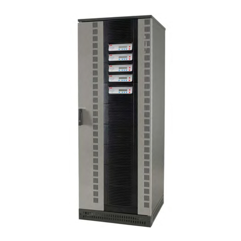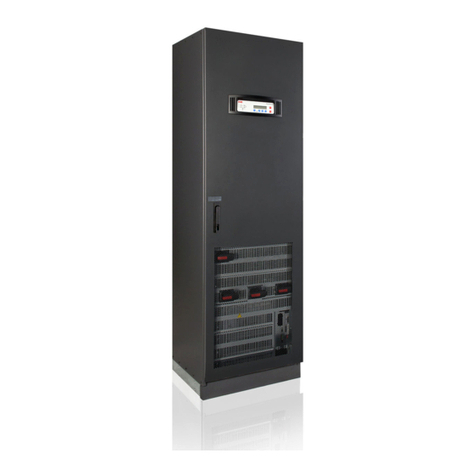
TLE Series 625 to 1000 PurePulse™ UL S2UPS Installation Guide / REV-B
Table of content Page
1Safety rules..................................................................................................................................................................6
1.1 Safety symbols and warnings ......................................................................................................................................8
1.2 Cyber security ..................................................................................................................................................................8
2Layout ..........................................................................................................................................................................9
2.1 Layout TLE Series 625 & 750 .........................................................................................................................................9
2.2 Layout TLE Series 1000................................................................................................................................................ 11
3Environment .............................................................................................................................................................. 13
3.1 Recycling instructions.................................................................................................................................................. 13
4Installation.................................................................................................................................................................14
4.1 Transport ........................................................................................................................................................................14
4.1.1 Dimensions and weights TLE Series 625 to 1000 ...................................................................................15
4.2Delivery ............................................................................................................................................................................16
4.3 Storage ............................................................................................................................................................................16
4.3.1 Storage of the UPS.........................................................................................................................................16
4.3.2 Storage of Battery..........................................................................................................................................16
4.4 Place of installation ...................................................................................................................................................... 17
4.4.1 UPS location..................................................................................................................................................... 17
4.4.2 Battery location .............................................................................................................................................. 21
4.5 Ventilation and cooling................................................................................................................................................22
4.6 Unpacking .......................................................................................................................................................................23
4.7 Inter cabinet connections ...........................................................................................................................................25
4.7.1 Cabinets positioning and interconnection for electrical safety grounding .....................................25
4.7.2 Bus bars interconnection .............................................................................................................................27
4.7.3 Control cables interconnection.................................................................................................................. 29
4.8 Electrical wiring .............................................................................................................................................................33
4.8.1 Utility input connection ................................................................................................................................33
4.8.2 Input/output over current protection and wire sizing......................................................................... 34
4.8.3 Data for Input/output and Battery over current protection and wire sizing...................................35
4.8.4 Installation requirements ............................................................................................................................ 38
4.9 Wiring connection .........................................................................................................................................................41
4.9.1 TLE Series 625 & 750 - Power connection with Common Input Utility.............................................. 45
4.9.2 TLE Series 625 & 750 - Power connection with Dual Input Utility ...................................................... 47
4.9.3 TLE Series 1000 - Power connection with Common Input Utility ...................................................... 50
4.9.4 TLE Series 1000 - Power connection with Dual Input Utility ................................................................52
4.9.5 Use of TLE Series 625 to 1000 in eBoost™ Operation Mode............................................................... 55
4.9.6 Use of TLE Series 625 to 1000 as Frequency Converter....................................................................... 56
4.10 RPA Parallel System connection.................................................................................................................................57
4.10.1 Power wiring of parallel units......................................................................................................................57
4.10.2 Parallel control bus connection.................................................................................................................. 58
4.10.3 Control bus cable location .......................................................................................................................... 60
4.11 “EPO - Emergency Power OFF” command connection........................................................................................ 62
4.12 TLE Series 1000 - Wiring of “IP Ring Bus” (option)............................................................................................... 64
5Connectivity interface..............................................................................................................................................65
5.1 Serial port J35µP - RS232 (Sub D, Female 9 pin).................................................................................................... 66
5.2 Customer interface board...........................................................................................................................................67
5.2.1 Connector J1 – RJ45 8P8C............................................................................................................................ 68
5.2.2 X1 terminal block - Output signals on voltage-free contacts.............................................................. 68
5.2.3 X1 terminal block - Programmable input free contacts........................................................................ 68
5.2.4 X2 terminal block – “EPO - Emergency Power Off” ................................................................................ 69
5.2.5 X1 terminal block - Gen Set Signaling (GEN ON) .................................................................................... 69
5.2.6 X1 terminal block - AUX External Maintenance Bypass......................................................................... 70
5.2.7 X1 terminal block - eBoost/IEMi control signal ...................................................................................... 70
6Notes .......................................................................................................................................................................... 71
6.1 Notes Form ..................................................................................................................................................................... 71
