ACME ARAS User manual

LED-PAR200 RGBW IP

1A
Menu
1. Safety Instructions............................................................................................................................1
2. Technical Specifications....................................................................................................................3
3. Installation and Connection .............................................................................................................4
4. How to set the unit...........................................................................................................................4
4.1 Rear Panel.......................................................................................................................................4
4.2 Main Function.................................................................................................................................6
5. How to control the unit ..................................................................................................................10
6. DMX512 configuration ................................................................................................................. 10`
7. DMX512 Connection.......................................................................................................................11
8.Troubleshooting...............................................................................................................................12
9. Fixture Cleaning..............................................................................................................................13

2A
1. Safety Instructions
WARNING
Please keep this User Manual for future consultation. If you sell the fixture to another user, be sure
that they also receive this instruction booklet.
Please unpack and check carefully there is no transportation damage before using the fixture.
Please disconnect main power before servicing and maintenance.
The unit must be installed in a location with adequate ventilation, at least 50cm from adjacent
surfaces. Be sure that no ventilation slots are blocked.
The maximum ambient temperature is Ta: 40℃. DO NOT operate it where the temperature is higher
than this.
DO NOT connect the device to any dimmer pack.
The housing must be replaced if they are visibly damaged.
Unit surface temperature may reach up to 60℃. Don’t touch the housing bare-hand during its
operation. Turn off the power and allow about 15 minutes for the unit to cool down before replacing
or serving.
There are no user serviceable parts inside the fixture. Do not open the housing or attempt any
repairs by yourself. In the unlikely event your fixture may require service, please contact your nearest
dealer.
In the event of serious operating problem, stop using the fixture immediately. Never try to repair the
fixture by yourself. Repairs carried out by unskilled people can lead to damage or malfunction. Please
contact the nearest authorized technical assistance center. Always use the same type spare parts.
Please read the instruction carefully which includes important
information about the installation, usage and maintenance.

3A
2. Technical Specifications
4/6/9 channel Mode;
Dimmer, Strobe;
Ideal for Professional stages, Concerts, clubs, discotheques, Mobile DJs, etc.
Input Voltage: AC100V~240V,50/60Hz
Total Power consumption:245W
Beam Angle:10°/15°/2 0 °/2 5 °/30°
IP Grade: IP X4
LED Sources: 300 W RGBW COB
Dimension/Weihgt:
281x257x534mm, 6Kg
11"x10.1"x21"in, 13.2lbs

4A
3. Installation and Connection
The unit should be mounted via its screw holes on the bracket. Always ensure that the unit is firmly fixed
to avoid vibration and slipping while operating. Always ensure that the structure to which you are
attaching the unit is secure and is able to support a weight of 10 times of the unit’s weight. Also always
use a safety cable that can hold 12 times of the weight of the unit when installing the fixture.
The equipment must be fixed by professionals. And it must be fixed at a place where is out of the touch
of people and has no one pass by or under it. The unit should be mounted in the height of 0 to 30m.
4. How to set the unit
4.1 Rear Panel
○
1Display: Show the various menus and the selected functions;
○
2 LED indicator:
POWER
On Power On
DMX
On DMX input present
○
3 Button:
MENU
To select the programming functions

5A
DOWN
To go forward in the selected functions
UP
To go backward in the selected functions
ENTER
To confirm the selected functions
○
4 Mains input/output::Use Powercon true one mains connection.
○
5DMX input/output:
For DMX512 link, use 3/5-pin XLR plug cable to input DMX signal, and to link the next unit.
The beam angle can be adjusted manually, which is 10°/15°/20°/2 5 °/30°.

6A
4.2 Main Function
To select any functions, press MENU button until the required one is shown on the display. Select the
function by ENTER button. Use DOWN and UP button to change the mode. Once the required mode has
been selected, press ENTER button to setup or it will return to the main functions without any change
after idling 8 seconds automatically. Back to the functions without any change press MENU button. The
main functions are shown below:
DMX 512 Address Setting
Select the , press the ENTER button and the display will blink. Use the DOWN and UP button to
change the DMX 512 address(001-512). Once the address has been selected, press the ENTER button to
setup or exit menu mode without any change after 8 seconds automatically. Back to the previous
functions without any change press the MENU button.

7A
Channel Mode
Select the , press the ENTER button. Use the DOWN and UP button to select the channel mode
(4CH/ 6CH/9CH). Once the address has been selected, press the ENTER button to setup or exit menu
mode without any change after 8 seconds automatically. Back to the previous functions without any
change press the MENU button.
Dimmer Mode
Select the , press the ENTER button. Use the DOWN and UP button to select (Dimmer
Mode 1)… (Dimmer Mode 4). Once selected, press the ENTER button to setup or exit menu
mode without any change after 8 seconds. Back to the functions without any change press the MENU
button again.
Dimmer mode 1 Dimmer mode 2 Dimmer mode 3 Dimmer mode 4
Optically Linear Square Law Inverse-Square Law S-Curve
Mode 1(Optically Linear): The increase in light intensity appears to be linear as DMX value is increased.
Mode 2(Square Law): Light intensity control is finer at low levels and coarser at high levels.
Mode 3(Inverse Square Law): Light intensity control is coarser at low levels and finger at high levels.
Mode 4(S-cure): Light intensity control is finger at low levels and high levels and coarser at medium
levels.
Dimmer Speed
Select the , press the ENTER button. Use the DOWN and UP button to select (Fast) or
(Smooth). Once selected, press the ENTER button to setup or exit menu mode without any
change after 8 seconds. Back to the functions without any change press the MENU button again.

8A
DMX State
Select the , press the ENTER button. Use the DOWN and UP button to select
(Blackout) or (Hold the last state) . Once selected, press the ENTER button to setup or exit
menu mode without any change after 8 seconds. Back to the functions without any change press the
MENU button again.
Display Inverse
Select the , press the ENTER button. Use the DOWN and UP button to select (Display
Normal) or (Display Inverse). Once selected, press the ENTER button to setup or exit menu
mode without any change after 8 seconds automatically. Back to the functions without any change press
the MENU button again.
White Balance
Select the , press the ENTERbutton. use the DOWN and UP button to select
/ / , You can choose values between 125-255,and press the ENTER button to
setup or automatically exit menu mode without any change after 8 seconds. To go back to the functions
without any change press the MENU button
Manual mode
Select the , press the ENTER button. Use the DOWN and UP button to select
RED(R000-R255)/ GREEN(G000-G255)/ BLUE(B000-B255)/ W(W000-A255)/
the brightness (d000-d255)or strobe(S000-S255). Once selected, press the ENTER
button to setup or exit menu mode without any change after 8 seconds automatically. Back to the
functions without any change press the MENU button again.
Auto Test

9A
Select the , press the ENTER button and the unit will run self-test by built-in program. To go back
to the functions press the MENU button again. Hold and press the MENU button about one second or
wait for one minute to exit the menu mode.
Temperature Display
Select the , press ENTER button and the display will show the temperature,To go back to the
functions press the MENU button.
Fixture Hour
Select the , press ENTER button and the display will show the number of working hours of the
unit. To go back to the functions press the MENU button.
Software Version
Select the , press ENTER button and the display will show the version of software of the unit.
To go back to the functions press the MENU button.
Factory setting
Select the , use the UP/DOWN button to select No or Yes (the fixture will reset to factory
settings and exit menu mode).
RDM function
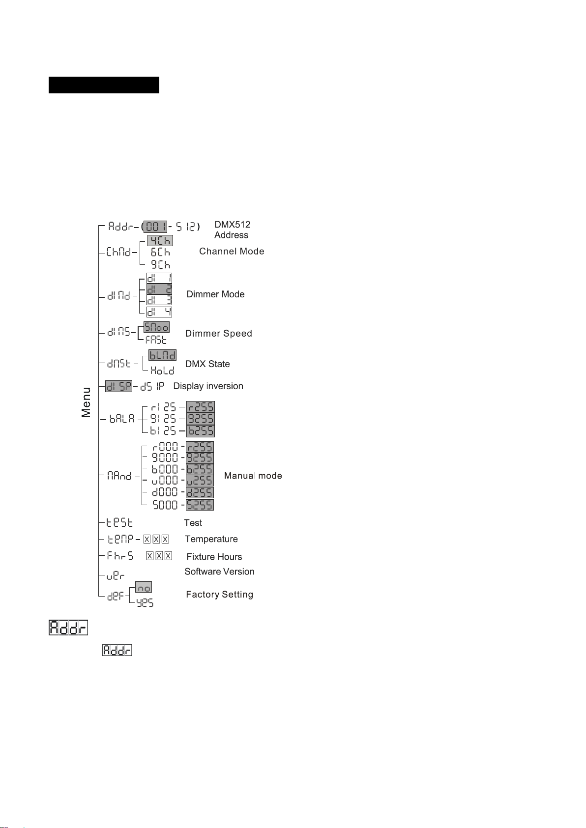
Select the DMX start menu to change the DMX 512 address(001-512)
Select the manufac tuner menu to display the lamp brand acme.
Select the device model description menu to select the lamp model ARAS.
Select the DMX performance menu to set the lamp channel 4channel / 6channel / 9channel.
Select the device label menu to change the lamp model. The initial model is ARAS.
Select the identity device menu, and the off / on option will appear. When you select on, the strobe will
appear on the lamp, and select off to turn off the strobe.
Select the device hours menu to display the lamp usage time.
Select the DMX personal menu to display the channel mode used by the luminaire.
Select reset device menu, and the warm / cold option will appear. When warm is selected, the lamp

10
A
will restart, and exit when
cold is selected.
Select the software menu and the lamp program version number will be displayed.
Select the LED menu to display the LED temperature of the lamp.
5. How to control the unit
1. By DMX controller;
No need to turn the unit off when you change the DMX address, as new DMX address setting will be
affected at once. Turn on the unit, under the DMX signal , the LED will display the saved channel address
(001-512).
6. DMX512 configuration
Channel Mode:

11A
7. DMX512 Connection
Mode connection:

12A
1. Connect the fixture together in a “daisy chain” by XLR plug cable from the output of the fixture to
the input of the next fixture. The cable cannot be branched or split to a “Y” cable. Inadequate or
damaged cables, soldered joints or corroded connectors can easily distort the signal and shut down
the system
2. The DMX output and input connectors are pass-through to maintain the DMX circuit when one of
the units’ power is disconnected.
3. At last fixture, the DMX cable has to be terminated with a terminator to reduce signal errors. Solder
a 120-ohm 1/4W resistor between pin 2(DMX-) and pin 3(DMX+) into a 3-pin XLR-plug and plug it in
the DMX-output of the last fixture.
4. Each lighting fixture needs to have an address set to receive the data sent by the controller. The
address number is between 0-511 (usually 0 & 1 are equal to 1).
5. 3/5 pin XLR connectors:.
3 pin XLR: Pin 1: GND, Pin 2: Negative signal (-), Pin 3: Positive signal (+), Pin 4: Blank, Pin 5: Blank
8.Troubleshooting
Following are a few common problems that may occur during operation. Here are some suggestions for
easy troubleshooting:
A. The fixture does not work, no light
1. Check the connection of power and main fuse.
2. Measure the mains voltage on the main connector.
B. Not responding to DMX controller

13A
1. DMX LED should be on. If not, check DMX connectors, cables to see if link properly.
2. If the DMX LED is on and no response to the channel, check the address settings and DMX polarity.
3. If you have intermittent DMX signal problems, check the pins on connectors or on PCB of the fixture
or the previous one.
4. Try to use another DMX controller.
5. Check if the DMX cables run near or run alongside to high voltage cables that may cause damage or
interference to DMX interface circuit.
C Error code
Err1 temperature fault
Check whether the test leads are in good contact and disconnected
Check if the thermistor is broken
Check PCB related circuit for damage
Err2 LED fan failure
Check whether the fan is stopped
Check whether PCB related detection circuit is damaged
Err3 main and auxiliary board communication fault check whether the main and auxiliary board
communication cable plugs are connected normally
Err4 switch power fan fault check whether the switch power fan is stopped
9. Fixture Cleaning
The cleaning of internal must be carried out periodically to optimize light output. Cleaning frequency
depends on the environment in which the fixture operates: damp, smoky or particularly dirty
surrounding can cause greater accumulation of dirt on the fixture’s optics.
Clean with soft cloth using normal glass cleaning fluid.
Always dry the parts carefully.
Clean the external optics at least every 20 days. Clean the internal optics at least every 30/60 days.

14A

15A
Declaration of Conformity
We declare that our products (lighting equipments) comply with the following
specification and bears CE mark in accordance with the provision of the
Electromagnetic Compatibility (EMC) Directive 2004/108/EC.
EN55103-1: 2009 ; EN55103-2: 2009;
EN61000-3-2: 2006 + A1:2009 + A2:2009; EN61000-3-3: 2008.
&
Harmonized Standard
EN 60598-1:2008 + All:2009; EN 60598-2-17:1989 + A2:1991;
EN 62471:2008; EN 62493: 2010
Safety of household and similar electrical appliances
Part 1: General requirements
Table of contents
Other ACME Dj Equipment manuals

ACME
ACME Genesis move 25R User manual

ACME
ACME Stage Blinder P4 User manual

ACME
ACME IU-01 User manual

ACME
ACME LS-608 RGB User manual

ACME
ACME LED WAVE 100 User manual

ACME
ACME SPLENDOR 90 User manual

ACME
ACME Ellipsoidal User manual

ACME
ACME FURY LED RGB User manual

ACME
ACME Color Par 36 User manual

ACME
ACME Color Spot User manual

ACME
ACME PAGEANT 300ZR User manual

ACME
ACME E-10 WW DXX User manual

ACME
ACME Ellipsoidal E-300 D2550 User manual

ACME
ACME LP-TS200 CW User manual

ACME
ACME LED-256D RGB User manual

ACME
ACME Diamonds LS-1010 RGB User manual

ACME
ACME DVS-2500 User manual

ACME
ACME LED-MTX25 IP User manual

ACME
ACME LED-BL4B User manual

ACME
ACME LED-737 User manual