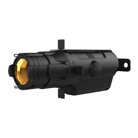
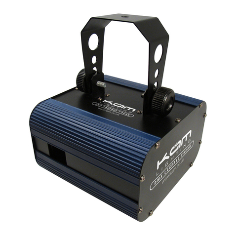
ACME Eventx 100 User manual

User Manual
Please read the instructions carefully before use
English Version 1.0

Table of contents
1. Introduction ………..……………………………………………………………………………………..……………………… 2
2. Safety instructions ……………………………………………………………………………………..………………………. 2
2.1 Preventing electric shock ………………………………...........................................................………. 2
2.2 Preventing burns and fire ……………………………...........................................................………… 3
2.3 Avoid personal injury …………………………………………...........................................................…. 3
3. Installation ………………..………………………………………………………………………………………….…………… 3
3.1 Connection to the main ……………………………………..........................................................……. 3
3.2 Mounting the fixture on a truss …………………………..........................................................…… 4
3.3 DMX 512 connection …………………………................................................................................ 5
3.4 DMX 512 controller ………………………….................................................................................. 6
3.5 IR remote control …………………………..................................................................................... 6
3.6 Wireless connection ……………………...................................................................................... 7
4. Description of EventX 100 …………………..……………………………………………………………………………… 9
4.1 Dimension ……………………....................................................................................................... 9
4.2 Overview ……………………....................................................................................................... 9
4.3 Control board ……………………................................................................................................ 10
5. Menu …………………..……………………………………………………………………………………………..…………… 12
6. DMX chart ……………..…………………………………………………………………………………………..……………. 23
7. LEE colors and RGB DMX values ……………..………………………………………………………………………… 25
8. Technical specifications ……………………………………………………………………….…………………………… 26
9. Troubleshooting ………………………………………………………………………………………..….…………………. 27
10. Maintenance and cleaning …………………………………………………………………….…….…………………… 27
1A

1 - Introduction
Thank you for your trust. We believe that products and service can satisfy you. Please keep this User Guide for future
consultation. If you sell the unit to another user, be sure that they also receive this instruction booklet.
All fixtures are intact from the manufact urer. Please, operator must be qualified and follow carefully the instructions of
this user manual. Artificial fault are not under guarantee repair.
The manufacturer will not accept liability for any resulting damages caused by the non-observance of this manual or
any unauthorized modification to the device.
Unpack and check carefully that there is no transportation damage before using the unit.
Inside the box you should find :
1. One EventX 100
2. One Power cable
3. One charger
4. One IR controler
5. One manual
Do install and operate by operator.
2 - Safety Instructions
The EventX 100 is a multi-environmental fixture with an IP-rating 65, intented for professional use only. It is not
suitable for household use.
Operator must be qualified and follow carefully the instructions of this user manual. Do not allow children to operate
the fixture.
Do not operate in dirty and dusty environment, also cleaning fixtures regularly.
Avoid power wires together arounding other cables.
In the event of serious operating problem, stop using the unit immediately.
Never turn on and off the unit time after time.
The housing, the lenses, or filter must be replaced if they are visibly damaged.
Do not open the unit as there are no user serviceable parts inside. Never try to repair the unit by yourself. Repairs
carried out by unskilled people can lead to damage or malfunction. Please contact the nearest authorized technical
assistance center.
Do use original packing materials once transport it again.
Disconnect the mains power if the fixture is not used for a long time.
If the device has been exposed to temperature changes due to environmental changes, do not switch it on
immediately. The arising condensation could damage the device. Leave the device switched off until it has reached
room temperature.
Be sure the place is well ventilled.
Always power off/unplug the fixture before removing any cover
Before operating, ensure that the voltage and frequency of power supply match the power requirements of the unit.
It’s important to ground the yellow/green conductor to earth in order to avoid electric shock.
Do not touch any wire during operation as there might be a hazard of electric shock.
Refer any service operation not described in this manual to a qualified technician.
Please read the instructions carefully which include important
informations about the installation, operation and maintenance
2.1 Preventing electric shock
2A

Look over power wires carefully, replace immediately if there is any damage.
Install at least 0.5m away from the objects to be illuminated.
Don’t connect the device to any dimmer pack.
Make sure there are no flammable materials close to the unit while operating, as it is fire hazard.
The unit must be installed in a location with adequate ventilation, at least 50cm from adjacent surfaces.
Be sure that no ventilation slots are blocked, otherwise the unit will be overheated.
The applicable temperature for Eventx 100 is between -40℃to 45℃. Don’t operate it where the temperature is lower
or higher than this.
The exterior of the fixture becomes hot during use. Avoid contact by persons and materials. Allow the fixture to cool
for at least 10 minutes before handling.
For temporary installation with clamps, ensure that the quarter-turn fasteners are turned fully and secured with a
suitable safety cable.
Use safety chain when fixes the unit specially when the fixture is working at height. This safety chain must be approved
for a safe working load of 10 times the weight of the fixture, and it must have a minimum gauge of 2 mm.
Ensure that any supporting structure used can hold at least 10 times the weight of all devices they support.
Unit surface temperature may reach up to 80℃. Don’t touch the housing bare-hand during its operation.
Do not look directly at the LED light beam while the fixture is on.
Do not operate the fixture with missing or clamaged of any part of the device.
3 - Installation
This product contains a sophisticated optical system which can cause damage the led if the front glass is expose to
sunlight or other strong light source.
So if these light source hits the front glass, sheild it or point the head in the opposite direction to the light source.
3.1 Connection to the main
If you use EventX 100 with his charger, ensure that the voltage and frequency of power supply match the power
requirements of the charger.
Input Charger: 100-240 Vac 50/60Hz
Output Charger: DC 29.4 V 4A
The earth has to be connected.
If you have any doubts about proper installation, consult a qualified electrician.
2.2 Preventing burns and fire
2.3 Avoid personal injury
Exposition warning
Warning
3A

3.2 Mounting the fixture on a truss
The unit should be mounted via its screw holes on the bracket. Always ensure that the unit is firmly fixed to avoid
vibration and slipping while operating. Always ensure that the structure to which you are attaching the unit is secure
and is able to support a weight of 10 times of the unit’s weight. Also always use a safety cable that can hold at least 10
times of the weight of the unit when installing the fixture.
The equipment must be fixed by professionals. And it must be fixed at a place where is out of the touch of people and
has no one pass by or under it.
The fixture must never be fixed swinging freely in the room.
This fixture can be placed on the stage floor or rigged on a truss without altering its operation characteristics.
Always use a safety cable that can hold at least 10 times of the weight of the unit when installing the fixture. Using the
attachment point marked “SAFETY WIRE” in the base of the fixture. This attachment point is designed to fit a
carabiner clamp, and turn around the truss as shown on the pictures below.
Note: If the safety wire is too long, whip it several times around the trusss in order to attach the fixture tightly. In case
of an accident, the way of the falling fixture will be shorter.
3
4A

3.3 DMX512 connection
- If you using a controller with 3 pins DMX output, you need to use a 3 to 5 pin adapter-cable.
- At last unit, the DMX cable has to be terminated with a terminator. Solder a 120 ohm 1/4W resistor between pin
2(DMX-) and pin 3(DMX+) into a 5-pin XLR-plug and plug it in the DMX-output of the last unit.
- Connect the unit together in a `daisy chain` by XLR plug from the output of the unit to the input of the next unit.
The cable can not branched or split to a `Y` cable. DMX 512 is a very high-speed signal. Inadequate or damaged
cables, soldered joints or corroded connectors can easily distort the signal and shut down the system.
INSTALLATION
5A

The DMX output and input connectors are pass-through to maintain the DMX circuit, when one of the units’ power
is disconnected.
- Each lighting unit needs to have an address set to receive the data sent by the controller. The address number is
between 0-511 (usually 0 & 1 are equal to 1).
The end of the DMX 512 system should be terminated to reduce signal errors.
3 pin XLR connectors are more popular than 5 pin XLR.
3 pin XLR: Pin 1: GND, Pin 2: Negative signal (-), Pin 3: Positive signal (+)
5 pin XLR: Pin 1: GND, Pin 2: Negative signal (-), Pin 3: Positive signal (+), Pin 4/Pin 5: Not used.
3.4 DMX 512 controller
Use universal DMX controller to control the units, you have to set DMX address from 1 to 512 channel so that the units
can receive DMX signal.
If all units have same DMX address, they will do simultaneously the same task as order the DMX controller.
If you set different address, each unit will start to respond of the DMX controller signal channel, based on the quantity
of control channels of the unit.
Press the MENU button up to when the DMX Address is showing on the display. Press the ENTER button and the
display will blink. Use the DOWN and UP button to change the DMX512 address. Once the address has been selected,
press and keep the ENTER button pressed up to when the display stops blinking or storing automatically 8 seconds
later. To go back to the functions without any change press the MENU button again.
Please refer to the following diagram to address your DMX512 channel for the first 4 units.
Channel mode Unit 1
Address
Unit 2
Address
Unit 3
Address
Unit 4
Address
5 Channels 1 6 11 16
7 Channels 1 8 15 22
8 Channels 1 9 17 25
3.5 IR remote control
STANDBY: Press the button to blackout the unit. It is invalid to press the other buttons when entry the Standby status;
And it will return to the original state when exit the Standby status.
FULL ON: Press and hold the button can show all the light, and it will return to the original state when release the
button.
ZOOM+/ZOOM-: Press these buttons to zoom in or zoom out.
DIMMER+/DIMMR-: Press these buttons to adjust the output intensity.
COLOR WHEEL +: Press the button to select the mexy color in the pre-programmed sequence. (Totally 33 colors)
COLOR WHEEL -: Press the button to select the previous color in the pre-programmed sequence. (Totally 33 colors)
FAST/MEDIUM/SLOW: Press these buttons to acive and setup the speed of show for color random.
RED/FUSHIA/BLUE/LIGHT BLUE/GREEN: Press these buttons to select the color.
2800K/3200K/4000K/5600K/8000K: Press these buttons to select the color temperature.
6A

3.6 Wireless connection
To setup the WDMX you need a Wireless Transceiver as our XP-LR 512 RT.
Press Menu button 2 seconds if the display is locked, else one impulsion on the Menu button is necessary to access to
the main menu.
The display will show “ DMX Address ”.
Use the UP/DOWN button to select Reset Function.
Press the ENTER button to confirm.
7A

The display will show “ Zoom Motor ”.
Use the UP/DOWN button to select Radio Clear Code.
Press the ENTER button to confirm.
Use the UP/DOWN button to select Yes or No.
Press the ENTER button to confirm.
The display will show “ Press up and down key, Hold over 5s ”.
Do not press now. You must first press the Function button of the Wireless Transceiver.
The green led named RF Link will flash.
Then press Up and Down buttons, hold them over 5s.
8A

During this process the display will show '' Radio Code Clearing ''
You can release Up and Down buttons when the display come back to the main menu. WF will appear.
4 - Description of EventX 100
4.1 Dimensions
9A

4.2 Overview
1. MENU: Activate display or to back to the last menu
2. ENTER: To confirm the selected functions
3. Display: To show the menu and the selected functions
4. UP: To go forward in the selected functions
5. DOWN: To go backward in the selected functions
6. Power Switch: Press to turn on/off the power
7. Power Charger: Connect to the power adapter to charge
8. DMX In: Water proof DMX socket input
9. DMX Out: Water proof DMX socket output
10. Antenna: To receive the wireless signal
11. IR Receiver: To receive the signal from the IR controller
12. Power Charger with Fight Case: Can charge the device when stowed in his fight case.
13. Safety wire/cord attachment point
10A

4. 3 Control board
Main menu with DMX or WiFi connection
1. Channel Mode number: 5, 7 or 8
2. Master or Slave setting: M=Master; S1=Slave1; S2=Slave2; S3=Slave3
3. Address DMX setting: 001 to 512
4. EventX 100 connection: DMX or WiFi
5. Display statue: Lock
6. Charge level of the battery.
Main Menu without connection
1. Fixture M/S setting: Master Mode, Slave 1 Mode, Slave 2 Mode or Slave 3 Mode
2. DMX State: Black Out, Last State or M/S
3. Display statue: Lock
4. Charge level of the battery.
11A

5 - Menu
To unlock the display, press the MENU button 2 seconds. If the lock Icon is not display, one impulsion on the Menu
button is necessary to access to the first Menu.
Use the DOWN and UP button to change the mode. Once mode wished selected, press the ENTER button to setup.
No action for one minute, it will automatically return to the main Menu and the display will be locked.
Back to the last menu without any change press the MENU button.
Once inside menu, you can also back to the main menu if you press 2 seconds the MENU button, the display will be
not locked.
The main functions are shown below:
...................................
12
12A

13A

DMX Settings
Press Menu button 2 seconds if the display is locked, else one impulsion on the Menu button is necessary to access to
the first menu. The display will show “ DMX Setting ”
Use the UP/DOWN buttons to select DMX Address, RDM Device ID or Channel Mode.
DMX Address
With this function, users are able to set the DMX start address to the projector.
DMX Address selected :
- Press the ENTER button to confirm.
- Use the UP/DOWN button to adjust the address from 001 to 512.
- Press the ENTER button to store.
- Press the MENU button back to the last menu or let the unit idle one minute to exit menu mode.
RDM Device ID
With this function, users will find the ID of the device to run it with RDM function.
RDM Device ID selected :
- Press the ENTER button to confirm.
- The display will show the ID.
- Press the MENU button back to the last menu or let the unit idle one minute to exit menu mode.
Channel Mode
With this function, users are able to set the number of channel he needs to run the device. More channels
means more functions are enable.
Channel Mode selected:
- Press the ENTER button to confirm.
- Use the UP/DOWN button to select 5 Channel, 7 Channel or 8 Channel.
- Press the ENTER button to store.
- Press the MENU button back to the last menu or let the unit idle one minute to exit menu mode.
DMX State
Press Menu button 2 seconds if the display is locked, else one impulsion on the Menu button is necessary to access to
the first menu. Press Enter button, the display will show “ DMX Setting ”
Use the UP/DOWN button to select DMX State. Press the ENTER button to confirm.
Use the UP/DOWN button to select Black Out, Last state or Master/Slave.
Black Out
This function will switch off the light if the device receive no DMX signal.
Black Out selected:
- Press the ENTER button to confirm.
- Press the MENU button back to the last menu or let the unit idle one minute to exit menu mode.
Last State
This function will let the device in the last state when he receives no DMX signal.
Last State selected:
- Press the ENTER button to confirm.
- Press the MENU button back to the last menu or let the unit idle one minute to exit menu mode.
Master/Slave
With this function, users are able to run Show Program.
- Press the ENTER button to confirm.
- Press the MENU button back to the last menu or let the unit idle one minute to exit menu mode.
14A

Fixture Settings
Press Menu button 2 seconds if the display is locked, else one impulsion on the Menu button is necessary to access to
the first menu. Press Enter button, the display will show “ DMX Setting ”.
Use the UP/DOWN button to select Fixture Settings. Press the ENTER button to confirm.
Use the UP/DOWN button to select Light Mode, Constant Color, Eco Mode, Dimmer Speed, Master/Slave, IR Switch.
Light Mode
In this menu, users are able to setup the light power.
Light Mode selected:
- Press the ENTER button to confirm.
- Use the UP/DOWN button to select Calibration or Max.
Calibration
This function is a factory color setting. We reduce the power of LED to give you the best match color
and white output across multiple EVENTX 100.
Calibration selected:
- Press the ENTER button to confirm.
- Use the UP/DOWN button to select Ye s or No.
- Press the ENTER button to confirm.
- Press the MENU button back to the last menu or let the unit idle one minute to exit menu mode.
Max Power
This function let users use the maximum power to the LED. The Max Power disable the calibration
mode, so the color and white could be different between fixtures and the battery life will be shorter.
Max Power let you acces to White Balance menu.
Max Power selected:
- Press the ENTER button to confirm.
- Press the MENU button back to the last menu or let the unit idle one minute to exit menu mode.
White Balance
This function set the white as you wish with the three primary color : Red, Green, Blue.
White Balance selected:
- Press the ENTER button to confirm.
- Use the UP/DOWN button to select the color you want ajusted: Red,Green or Blue.
- Press the ENTER button to confirm.
- Use the UP/DOWN button to adjust the value.
- Press the ENTER button to confirm.
- Press the MENU button back to the last menu or let the unit idle one minute to exit menu
mode.
Constant Color
This function manage the power of Red, Green, Blue leds to get nearly the same color depending the
temperature of the device.
Constant color selected:
- Press the ENTER button to confirm.
- Use the UP/DOWN button to select Ye s or No.
- Press the ENTER button to confirm.
- Press the MENU button back to the last menu or let the unit idle one minute to exit menu mode.
Eco. Mode
This function manages the power of the battery. Also, It let you have a constant lighting intensity during his
heating phase.
Eco. Mode selected:
- Press the ENTER button to confirm.
- Use the UP/DOWN button to select Ye s or No.
- Press the ENTER button to confirm.
15A

- Press the MENU button back to the last menu or let the unit idle one minute to exit menu mode.
Dimmer Speed
This function manages the dimmer speed. It interacts when the light intensity is changed.
Smooth mode gives to your output light a continuous effect but there is some latency between the time you
change the intensity of the light manually and visually.
Fast mode gives an instantaneous response to your new adjustment of light intensity. But it can appear some
bad effect such as flash or light step intensity.
Dimmer Speed selected:
- Press the ENTER button to confirm.
- Use the UP/DOWN button to select Smooth or Fast.
- Press the ENTER button to confirm.
- Press the MENU button back to the last menu or let the unit idle one minute to exit menu mode.
Master/Slave
This function changes the statue when EventX 100 is working with Show Program or IR system.
Master/Slave setting selected:
- Press the ENTER button to confirm.
- Use the UP/DOWN button to select Master, Slave1, Slave2 or Slave3.
- Press the ENTER button to confirm.
- Press the MENU button back to the last menu or let the unit idle one minute to exit menu mode.
IR Switch
This function enables or disables the IR system.
IR Switch selected:
- Press the ENTER button to confirm.
- Use the UP/DOWN button to select Ye s or No.
- Press the ENTER button to confirm.
- Press the MENU button back to the last menu or let the unit idle one minute to exit menu mode.
Show Program
In this menu, users are able to build a show. Each program is constituted of one or more Acts which are themselves
composed of one or more Scenes.
Press Menu button 2 seconds if the display is locked, else one impulsion on the Menu button is necessary to access to
the first menu. Press Enter button, the display will show “ DMX Setting ”.
Use the UP/DOWN button to select show program. Press the ENTER button to confirm.
Use the UP/DOWN button to select Run Program, Edit Program, Edit Act or Edit Scene.
Run Program
In this menu, users are able to select the program show they want run. Users can select to run 3 different
programs or all in the same time.
Program Show 1 will allow the identified machines Master or Slave1 (in the menu Fixture Setting , M / S Setting)
to run.
Program Show 2 will allow the identified machines Slave2 (in the menu Fixture Setting , Master / Slave) to run.
Program Show 3 will allow the identified machines Slave3 (in the menu Fixture Setting , Master / Slave) to run.
Use the UP/DOWN button to select Run Program. Press the ENTER button to confirm.
Use the UP/DOWN button to select Program Show 1, Program Show 2, Program Show 3 or All Program.
Program Show1, 2, 3 or all
In this menu, users are able to select the run mode of the program show he needs.
Autorun: If EventX 100 is in mode M/S in the menu DMX State, the program will start automatically when the
unit is power on.
Run: If EventX 100 is in mode M/S in the menu DMX State, the program can start only when the user selects
Run and confirm.
Program Show 1, 2, 3 or all selected:
- Press the ENTER button to confirm.
MENU
16A

- Use the UP/DOWN button to select Autorun or Run.
- Press the ENTER button to confirm.
- Press the MENU button back to the last menu or let the unit idle one minute to exit menu mode.
Edit Program
In this menu, users are able to edit program.
Edit Program selected:
- Press the ENTER button to confirm.
- Use the UP/DOWN button to select Program Show 1, Program Show 2 or Program Show 3.
Program Show 1, Program Show 2 or Program Show 3
In this menu, users are able to built his program sequences.
Program Show 1, 2 or 3 selected:
- Press the ENTER button to confirm.
- Use the UP/DOWN button to select Add Act, Delete, Clear All or View Program.
Add Act
With this function, users are able to add one Act, between Act 1 to Act 10.
Add Act selected:
- Press the ENTER button to confirm.
- Use the UP/DOWN button to select between Act 1 to Act 10.
- Press the ENTER button to confirm.
Delete
With this function, users are able to delete one Act, between Act 1 to Act 10.
Delete selected:
- Press the ENTER button to confirm.
- Use the UP/DOWN button to select between Act 1 to Act 10.
- Press the ENTER button to confirm.
Clear All
With this function, users are able to delete all acts of the program selected
Clear All selected:
- Press the ENTER button to confirm.
View Program
With this function, users are able to view the program selected (only one cycle)
View Program selected:
- Press the ENTER button to confirm.
Edit Act
In this menu, users are able to edit acts.
Edit Act selected:
- Press the ENTER button to confirm.
- Use the UP/DOWN button to select Act 1 to Act 10.
Act 1 to Act 10
In this menu, users are able to built his program sequences.
Act 1 to Act 10 selected:
- Press the ENTER button to confirm.
- Use the UP/DOWN button to select Add Scene, Delete, Clear All or View Program.
Add Scene
With this function, users are able to add one Scene, between Scene 1 to Scene 20.
Add Scene selected:
17A

- Press the ENTER button to confirm.
- Use the UP/DOWN button to select between Scene 1 to Scene 20.
- Press the ENTER button to confirm.
Delete
With this function, users are able to delete one Scene, between Scene 1 to Scene 20.
Delete selected:
- Press the ENTER button to confirm.
- Use the UP/DOWN button to select between Scene 1 to Scene 20.
- Press the ENTER button to confirm.
Clear All
With this function, users are able to delete all scenes of the act selected
Clear All selected:
- Press the ENTER button to confirm.
View Program
With this function, users are able to view the program in the act selected (only one cycle).
View Program selected:
- Press the ENTER button to confirm.
Edit Scene
In this menu, users are able to edit scenes.
Edit Scene selected:
- Press the ENTER button to confirm.
- Use the UP/DOWN button to select Clear all, Scene 1 to Scene 20.
Clear all
With this function, users are able to clear all data of all scenes.
Clear all selected:
- Press the ENTER button to confirm.
- Use the UP/DOWN button to select Ye s or No.
- Press the ENTER button to confirm.
Scene 1 to Scene 20
In this menu, users are able to built scenes.
Scene 1 to Scene 20 selected:
- Press the ENTER button to confirm.
- Use the UP/DOWN button to select Modify, Copy DMX, Copy Last or Clear.
Modify
In this menu, users are able to modify one Scene, between Scene 1 to Scene 20.
Modify selected:
- Press the ENTER button to confirm.
- Use the UP/DOWN button to select Wait Time, Fade Time, Red, Green, Blue, White, Zoom, Dimmer or
Strobe.
Wait Time
With this function, users set the wait (static) time to current scene in second.
Wait Time selected:
- Press the ENTER button to confirm.
- Use the UP/DOWN button to change the value. (0 to 255)
- Press the ENTER button to confirm.
- Press the MENU button back to the last menu or let the unit idle one minute to exit menu mode.
18A

Fade Time
With this function, users set the fade-in (transition) time to current scene in second. (0 to 255)
Fade Time selected:
- Press the ENTER button to confirm.
- Use the UP/DOWN button to change the value.
- Press the ENTER button to confirm.
- Press the MENU button back to the last menu or let the unit idle one minute to exit menu mode.
Red
With this function, users can adjust the light power of red output. ( 0 = Black ; 255 = 100% Red )
Red selected:
- Press the ENTER button to confirm.
- Use the UP/DOWN button to change the value. (0 to 255)
- Press the ENTER button to confirm.
- Press the MENU button back to the last menu or let the unit idle one minute to exit menu mode.
GREEN
With this function, users can adjust the light power of green output. ( 0 = Black ; 255 = 100% green )
Green selected:
- Press the ENTER button to confirm.
- Use the UP/DOWN button to change the value. (0 to 255)
- Press the ENTER button to confirm.
- Press the MENU button back to the last menu or let the unit idle one minute to exit menu mode.
Blue
With this function, users can adjust the light power of blue output. ( 0 = Black ; 255 = 100% Blue )
Blue selected:
- Press the ENTER button to confirm.
- Use the UP/DOWN button to change the value. (0 to 255)
- Press the ENTER button to confirm.
- Press the MENU button back to the last menu or let the unit idle one minute to exit menu mode.
White
With this function, users can adjust the light power of white output. ( 0 = Black ; 255 = 100% White )
White selected:
- Press the ENTER button to confirm.
- Use the UP/DOWN button to change the value. (0 to 255)
- Press the ENTER button to confirm.
- Press the MENU button back to the last menu or let the unit idle one minute to exit menu mode.
Zoom
With this function, users can adjust the beam angle. ( 0 = Open ; 255 = 100% Close )
Zoom selected:
- Press the ENTER button to confirm.
- Use the UP/DOWN button to change the value. (0 to 255)
- Press the ENTER button to confirm.
- Press the MENU button back to the last menu or let the unit idle one minute to exit menu mode.
Dimmer
With this function, users can adjust the intensity of light power output. ( 0 = Off ; 255 = 100% light )
Dimmer selected:
- Press the ENTER button to confirm.
- Use the UP/DOWN button to change the value. (0 to 255)
- Press the ENTER button to confirm.
- Press the MENU button back to the last menu or let the unit idle one minute to exit menu mode.
19A
This manual suits for next models
1
Table of contents
Other ACME Dj Equipment manuals

ACME
ACME ORION XP-260 BEAM User manual

ACME
ACME ARAS User manual

ACME
ACME XA-500 User manual

ACME
ACME Color Par 36 User manual

ACME
ACME LED-256D RGB User manual

ACME
ACME Dotline 360 User manual

ACME
ACME Theatre LED Colour Flood User manual

ACME
ACME Genesis move 25R User manual

ACME
ACME LED-BR10 User manual

ACME
ACME LED-RC8 User manual

ACME
ACME Ellipsoidal 10 DMX User manual

ACME
ACME LED-635S User manual

ACME
ACME TB-1010QW II User manual

ACME
ACME MP-400Z IP User manual

ACME
ACME MH-275R User manual

ACME
ACME ENERGY HYBRID User manual

ACME
ACME LED WAVE 100 User manual

ACME
ACME CYC-200 FC User manual

ACME
ACME SPLENDOR 90 User manual

ACME
ACME Spartan Hybrid User manual