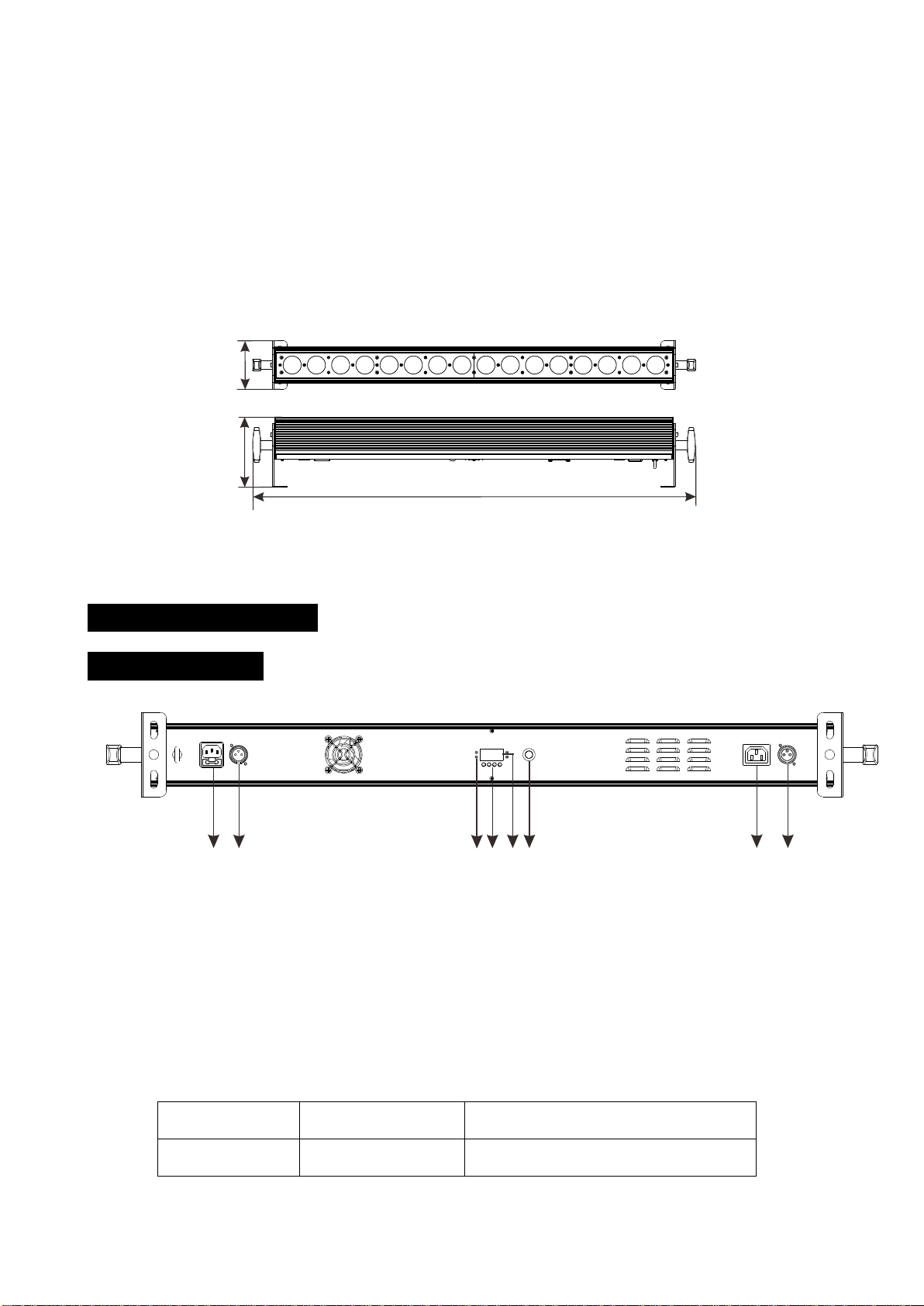
DMX 512 Address Setting
Press the MENU button up to when the is shown on the display. Pressing ENTER button
and the display will blink. Use DOWN and UP button to change the value. Once the mode has
been selected, press the ENTER button to setup, to go back to the functions without any change
press the MENU button again. Hold and press the MENU button about one second or wait for one
minute to exit the menu mode.
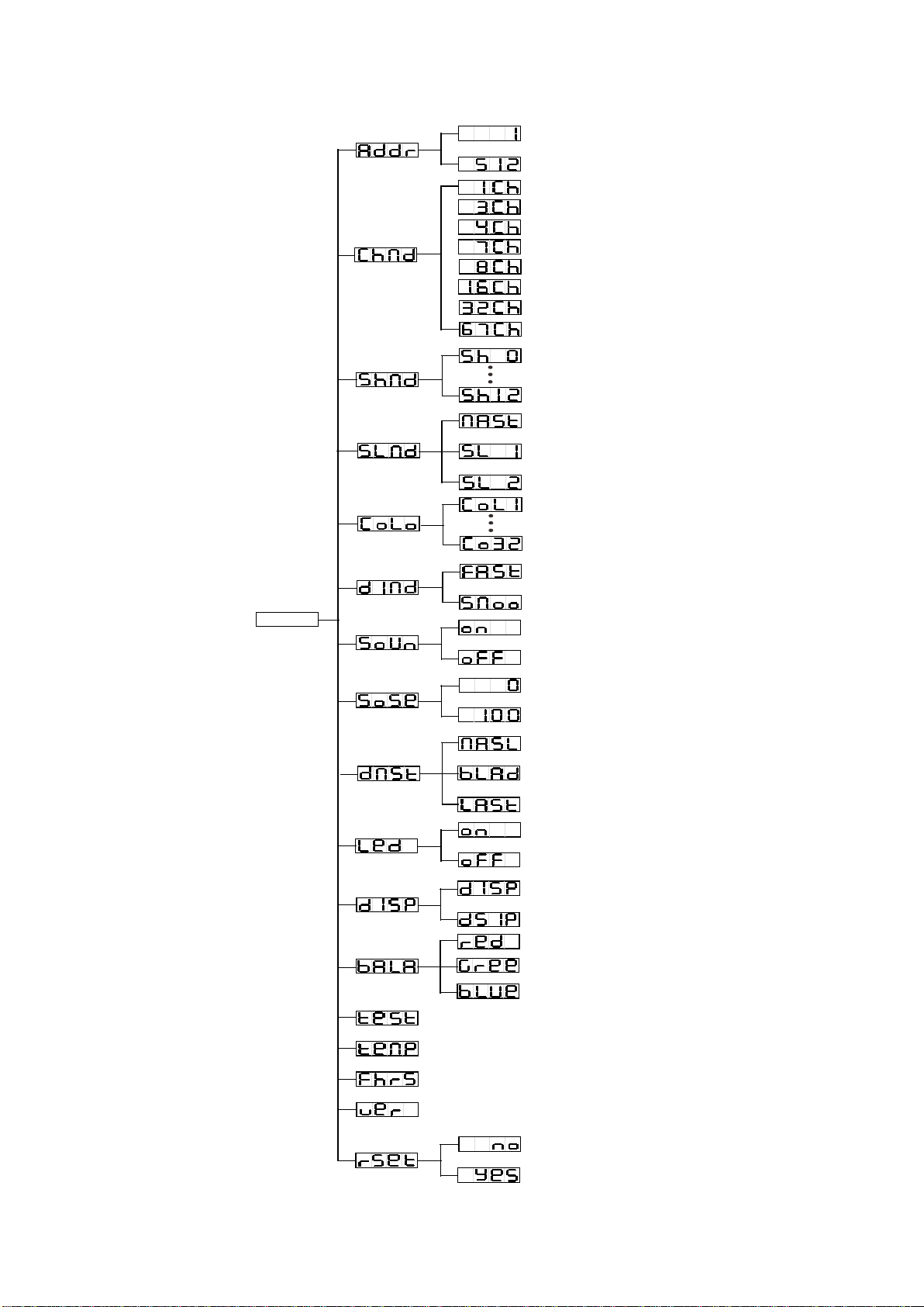
Channel Mode
Press the MENU button to show on the display. Press the ENTER button and the display
will blink. Use the DOWN and UP button to select the 1ch, 3ch,4ch,7ch,8ch,16ch,32ch or 67ch.
Once the mode has been selected, press the ENTER button to setup, to go back to the functions
without any change press the MENU button again. Hold and press the MENU button about one
second or wait for one minute to exit the menu mode.
Show Mode
Press the MENU button up to when the is shown on the display. Pressing the ENTER
button. Use DOWN and UP button to select the (Show 0) …… (Show 12)
mode.Once the mode has been selected, press the ENTER button to setup, to go back to the
functions without any change press the MENU button again. Hold and press the MENU button
about one second or wait for one minute to exit the menu mode.
Slave Mode
Press the MENU button up to when the is shown on the display. Pressing the ENTER
button. Use DOWN and UP button to select the (slave 1), (Slave 2) or
(master) mode.Once the mode has been selected, press the ENTER button to setup, to
go back to the functions without any change press the MENU button again. Hold and press the
MENU button about one second or wait for one minute to exit the menu mode.
7A