manuals.online logo
Brands
  1. Home
  2. •
  3. Brands
  4. •
  5. ACO
  6. •
  7. Intercom System
  8. •
  9. ACO FAM-PV Series Installation instructions

ACO FAM-PV Series Installation instructions

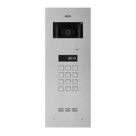
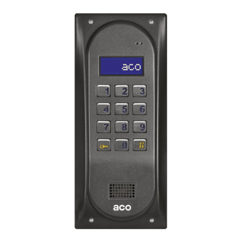
USER INSTRUCTION FOR - FAM-PV SERIES DIGITAL VIDEO DOOR
ENTRY SYSTEM
62-002 Suchy Las, ul. Diamentowa 7, tel/fax 61 843 93 71
www.aco.com.pl
TECHNICAL PARAMETERS
Power supply: 15V ±10% DC
Power consumption in standby mode: ~2.8W
Power consumption of FAM-PV-2NPZS ACC panel: max. 350mA, without E-lock
Number of proximity key fobs (version with built-in ACC): 192 key fobs
Permitted load on E-lock output: 1A
Front: stainless steel; mounted with 3mm Allen (hexagon) screws
Required space for flush-mounted panel: 286 x 90 mm
Hole size for flush-mounted box (ABS): 269 x 73 x 32mm
Size of the optional PNT2-FAM-PRO/PV surface-mounted box (to be purchased separately): 288.4x92.4x(53/39)
PANEL INSTALLATION AND CONNECTION
The panel should be assembled so as to minimise the impact of adverse weather conditions, in particular water. Make sure that the
camera is installed at the desired height. Typically, that height is 1.60 m from the ground. For optimal field of view of the camera,
verify the installation location and position of the panel by trial and error. Avoid locations where the camera lens may be exposed to
direct, perpendicular, light (from the sun, streetlamps, etc.). Install the flush-mounted back box (or flush-mounted adapted) in the
appropriate wall opening, using holes 5and raw plugs (or screws) as well as gypsum; make sure that the back side of the box flange
Ais flush with the mounting surface. When mounting on a steel pole (similar structure with a maximum wall thickness of 32 mm), use
an additional set of gaskets and screws 3 - available as an option. Run the wires through hole 1in the box base (cut out the cap if
larger hole is needed). Use additional holes 4for makeshift installation with nails etc. when mounting the unit in soft materials such
as polystyrene. Holes 4also make installation easier when using mounting foam. The cover cap 2should be cut out in order to
install the add-on module in its place. For the best possible tightness, cut out only those holes that are necessary to install the panel.
Check the condition of the gasket on box B. Cracks, deformations and soiling of the gasket may lead to loss of tightness.
Connect 15V DC power supply voltage to "+DC" and "GND" terminals of the panel. Connect the E-lock, no specific polarity to be
observed, to "ELOCK" terminals. When using a reversible E-lock, change the panel settings and insert jumper Z1 (can be found
under panel terminals). When using a reversible E-lock, voltage appears at the "ELOCK" output depending on the power supply of
the panel: 15VDC - use suitable reversible E-lock. It is also possible to use the MOD-DC-12V module for 12VDC power supply of
reversible E-lock if the door entry unit is supplied by a 15VDC power supply. Connect the monitor bus (UTP) to relevant panel
terminals, as per the wiring diagram and UTP colours (T568B standard). Before turning the power on, check for possible short circuits
between the wires and make sure that the wires conduct current and are properly connected to RJ45.
Note! To ensure proper functioning and safety of the door entry unit, connect the grounding terminal on the metal frame with relevant
protective installation (PE). (ground) with a suitable protective installation (PE).
Allen wrench
3 mm
Arrange the following cables in their maximum lengths to the panel:
2 wires x 1mm2- power supply
2 wires x 0.75mm2- to E-lock
UTP (standard T568B) - bus, max. 70m - from the panel (or the last power supply unit), 300m in total - when using
additional power supplies.
If cross-sections are smaller and connections that are too long, voltage drops may occur, causing the panel to malfunction.
To extend the length of cables, their cross-section must be increased.
WIRING DIAGRAM
Note!
If the system features only one monitor, no video splitter is necessary
and the monitor is connected at the end of the UTP bus leaving the
panel. It is then absolutely necessary to connect the monitor power
supply by connecting the bus cable: orange and brown together to
"+DC" terminal of the panel (in this case the maximum distance
between the panel and the monitor is 70m). When using Video splitters,
cable length may be extendedup of 300m from the panel to the monitor,
assuming that the splitter, with a power supply Ato it - is within 70m
from the monitor. (It is then not required to connect the orange and
brown wires to the panel - it’ enough to use jumper J1 on the splitter).
MONITOR INSTALLATION AND CONNECTION
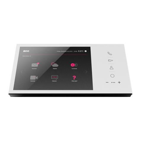
When installing the monitor refer to the user instruction delivered with the monitor.
When connecting the monitor, make sure the RJ45 plug (standard T568B) is crimped. Before turning on the power, make sure that
all RJ45 plugs are properly crimped (the same way), that the wires conduct current and check for possible short circuits between the
wires. If even one RJ connector is badly crimped or in case of a short circuit between wires, the video inside unit, splitter or combiner
may be damaged.
Note! Also make sure that addresses are properly configured in the monitor. For panels with direct call buttons (ring buttons), button
addresses are pre-set from 1 to 6 (depending on panel model). The lowest button corresponds to address 1. If no direct button is
present buttons, the addresses of the monitors are called directly from the numeric keypad (pre-set at 1 to 10).
There may be monitors with the same addresses in the video system, which means that several monitors can call at the same time
when the call button is pressed. If have an additional indoor units, calling simultaneously with the monitor, use INS-UP720MR, UP800
indoor units. Use INS-UP720MR, UP800 indoor units also when only one indoor unit needs to be installed to call upon pressing the
call button.
INPUT
VS
VIDEO
LINE
INPUT
ELOCK
-DC
POWER
+DC
POWER
GND
max 1A
Power
15 V DC
ROZDZIELACZ
/ SPLITTER
ML
1 Orange and white
2 Orange
3 Green and white
4 Blue
5 Blue and white
6 Green
7 Brown and white
8 Brown
Power supply
Video
- Signal line (GND)
Power supply
+ Signal line (L+)
ON
Address: 1
Address: 2
Address: 3
Address: 46
ON
ON
ON
CODE/ADDRESS
CODE/ADDRESS
CODE/ADDRESS
CODE/ADDRESS
ON
OFF
USING THE PANEL
- Turning the panel on
Each time the power is turned on, it will start beeping for 30 seconds. This function is used to stabilise the operating conditions of the
handset line and to restore the default codes and panel settings. It can always be cancelled using lower call button or the "#" button.
- Calling:
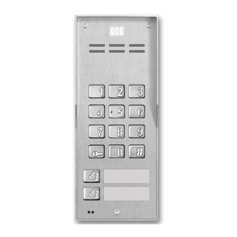
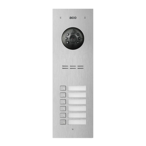
Panels with direct call buttons: To call the subscriber press the appropriate ringer button - the handset in the apartment being
called will start ringing.
Panels with only the numeric keypad: To call the subscriber, select the number of the apartment using the keys on the keypad
(pre-set from 1 to 10). Within 3 seconds the indoor unit in the apartment will start ringing.
The panel sends two ringing tones and sets itself to stand by waiting for the handset to be picked up. If the call is not answered within
20s, another single signal is sent. If the monitor handset is not picked up within approximately 40s, the panel will automatically switch
from calling to standby mode. Calling can be cancelled at any time by pressing the "#" button. If the call is answered, the connection
to the panel is established. Now conversation is possible and the door can be opened. The connection can last up to 2 minutes.
- Using a code or proximity key fob (ACC) :
To open the door (to the E-lock), use the code by entering it on the numeric keypad or, in panel standby mode, by placing a key
fob to the lowest description window. For panels with a numeric keypad and direct dial buttons, the pre-set codes are 1111 (for the
lower button), 2222 (for the upper button). For panels with only a numeric keypad itself, use the resident code from the pre-
programmed code table (code table attached to the panel). To do this, select the number of the apartment, press the "key" button
and then select the relevant code (assigned to the apartment as per the code table).
If the code (or the proximity card) is preceded by pressing the key twice, it will activate an additional device, such as a gateway
(this requires an optional I/O module connected to the panel).
The panel has a function to notify residents when the code or proximity card or key fob is used - by a short triple beep emitted
by the handset to which the code or key fob is assigned.
Note! It is recommended to change the codes upon installation of the panel is complete. Code change by the user in panels with
direct call buttons: Enter the current code, then within 1.5 second press and hold the "key" button (for approximately 4s), until the
panel emits the sound of accessing the code change procedure. Then enter a new four-digit code. For panels with only the numeric
keypad, the code can be changed from the installer’s menu (refer to extended user instruction).
To add and remove proximity key fobs, use the ACC computer program, version v3.5 or later, available at www.aco.com.pl. and
connect the panel to the computer using the optional CDN-USB cable (to be purchased separately).
- Restoring codes and panel settings to factory default settings and deleting all key fobs:
Turn the panel power supply off, wait 5 seconds, turn the power on again. The panel will beep for 30 seconds. Press the "#"
button during this time and press at the same time (immediately) press:
- keys 1 and 7 to restore the lower key code to 1111 (for panels with direct dial buttons)
- keys 2 and 7 to restore the top button code to 2222 (for panels with direct dial buttons)
- keys 2, 5, 8 to restore all factory settings, including both codes (in models without a numeric keypad, press the lower calling key
after the first beep that can be heard after power is turned on and hold it until the factory settings reset procedure is started).
- Handset line failure: The panel detects failures (short circuit) of the handset line - indicated by blinking of keypad backlight. During
this time, E-lock can be activated by pressing any button and building can be entered. When the correct state of the line is detected
(when short circuit ceases), the panel is automatically restored to normal operation.
USING THE OPERATION
To answer the call while it is ringing, simply pick up the handset of the monitor. During the connection, it is possible to open the
door using the “key” button. Additional devices, such as a gateway, can be activated using the "F2" function key (only with optional
I/O module connected to the panel).
The call ends automatically when the handset is hung up.
The ringing volume of the monitor can be adjusted in stand-by mode (using the switch at the bottom of the unit). Door
can be opened in standby mode by pressing the “key” button.
Refer to the extended user manual of FAM-PV series panels available at www.aco.com.pl to find out more features of the FAM-PV
series panels (programming advanced functions, systems with greater number of panels, interconnection with other ACO systems:
CDNP, Inspiro, and basic troubleshooting). All settings may also be changed using the FAM_P computer software.
Software can be downloaded from www.aco.com.pl. (Connect the panel to the computer using the optional CDN-USB
cable.)
RULES FOR STORING WASTE ELECTRICAL EQUIPMENT
Waste electrical equipment must not be disposed of with other waste. It should be stored in places designated for this purpose. For
this purpose, please contact the responsible institutions or companies involved in waste recycling.
- Directive 2002/96/EC of 27.01.2003
IU0204enVG.1950
This manual suits for next models

1

Other ACO Intercom System manuals

ACO acoGO! P User guide

ACO

ACO acoGO! P User guide

ACO CDNP7ACC User manual

ACO

ACO CDNP7ACC User manual

ACO INSPIRO+VIDEO User manual

ACO

ACO INSPIRO+VIDEO User manual

ACO GLASS-IP-7 User guide

ACO

ACO GLASS-IP-7 User guide

ACO COMO-PRO User manual

ACO

ACO COMO-PRO User manual

ACO INS-UC 720M User manual

ACO

ACO INS-UC 720M User manual

ACO INS-UA720M User manual

ACO

ACO INS-UA720M User manual

ACO INSPIRO 4 Series User manual

ACO

ACO INSPIRO 4 Series User manual

ACO MOD-SPK-PRO User manual

ACO

ACO MOD-SPK-PRO User manual

ACO CDNP6ACC User manual

ACO

ACO CDNP6ACC User manual

ACO CDNP7ACC User manual

ACO

ACO CDNP7ACC User manual

ACO FAM-P Series User manual

ACO

ACO FAM-P Series User manual

ACO INS-UP 720B User manual

ACO

ACO INS-UP 720B User manual

ACO INSPIRO+audio User manual

ACO

ACO INSPIRO+audio User manual

ACO FAM-P Series User manual

ACO

ACO FAM-P Series User manual

ACO CDNP6ACC Installation instructions

ACO

ACO CDNP6ACC Installation instructions

ACO INSPIRO 1 Series User manual

ACO

ACO INSPIRO 1 Series User manual

ACO CDNP6ACC User manual

ACO

ACO CDNP6ACC User manual

ACO Familio PRO User manual

ACO

ACO Familio PRO User manual

ACO COMO-PRO-POST-A1 Series User manual

ACO

ACO COMO-PRO-POST-A1 Series User manual

ACO FAM-P Installation instructions

ACO

ACO FAM-P Installation instructions

ACO COMO-PRO-V Series User manual

ACO

ACO COMO-PRO-V Series User manual

Popular Intercom System manuals by other brands

SES SAT2 User and installer guide

SES

SES SAT2 User and installer guide

XtendLan DPC-518ID user manual

XtendLan

XtendLan DPC-518ID user manual

Westinghouse WHI-3S - One Piece Intercom Unit owner's manual

Westinghouse

Westinghouse WHI-3S - One Piece Intercom Unit owner's manual

Akuvox IT88 Series Admin guide

Akuvox

Akuvox IT88 Series Admin guide

ABB H82351 Series operating instructions

ABB

ABB H82351 Series operating instructions

Honeywell KMA 28B System installation and operation manual

Honeywell

Honeywell KMA 28B System installation and operation manual

Bticino Small Entrance Panel Compact User and installation manual

Bticino

Bticino Small Entrance Panel Compact User and installation manual

Philips WelcomeEye Connect 2 user manual

Philips

Philips WelcomeEye Connect 2 user manual

Extron electronics MediaLink IPI 201 Specifications

Extron electronics

Extron electronics MediaLink IPI 201 Specifications

PROEL DBEVF user manual

PROEL

PROEL DBEVF user manual

GVS T Series user manual

GVS

GVS T Series user manual

golmar GB2 Nexa Modular quick guide

golmar

golmar GB2 Nexa Modular quick guide

Aiphone TB-12F instructions

Aiphone

Aiphone TB-12F instructions

Riedel Acrobat WB-2 user manual

Riedel

Riedel Acrobat WB-2 user manual

Hyundai Telecom HAF-R1071 instruction manual

Hyundai Telecom

Hyundai Telecom HAF-R1071 instruction manual

Midland BT Next Instruction

Midland

Midland BT Next Instruction

ESP aperta EZTAG3 user manual

ESP

ESP aperta EZTAG3 user manual

Valcom V-2924A user guide

Valcom

Valcom V-2924A user guide

manuals.online logo
manuals.online logoBrands
  • About & Mission
  • Contact us
  • Privacy Policy
  • Terms and Conditions

Copyright 2025 Manuals.Online. All Rights Reserved.