manuals.online logo
Brands
  1. Home
  2. •
  3. Brands
  4. •
  5. ACO
  6. •
  7. Intercom System
  8. •
  9. ACO INSPIRO 4 Series User manual

ACO INSPIRO 4 Series User manual

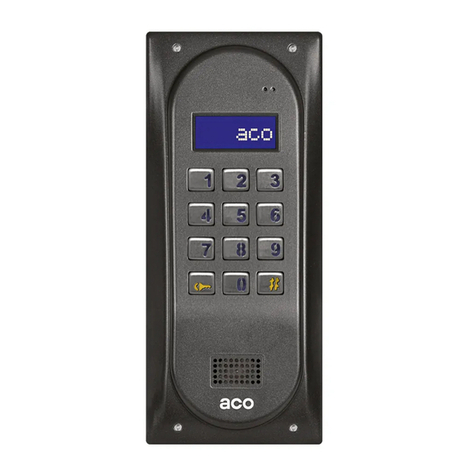
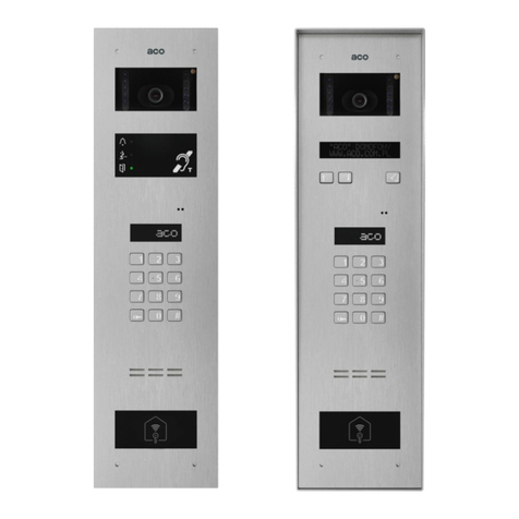
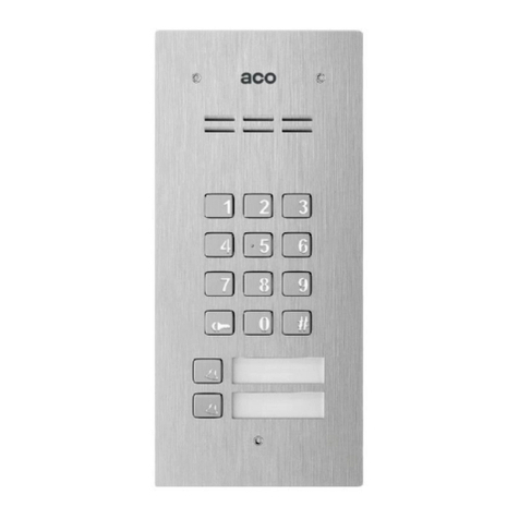
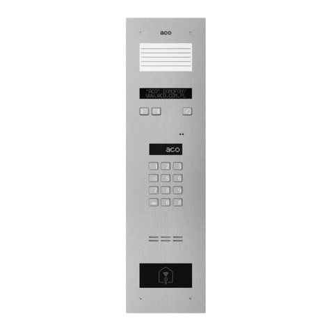
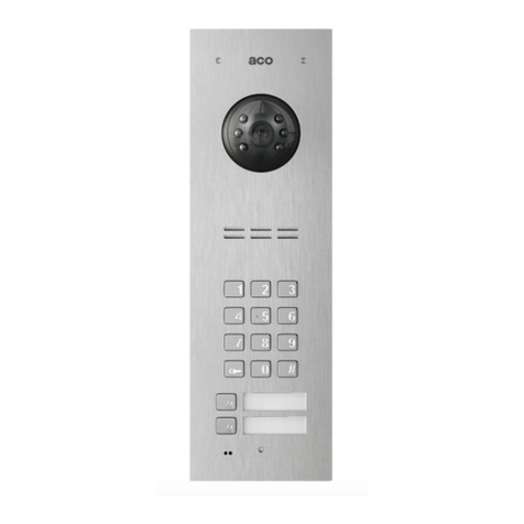
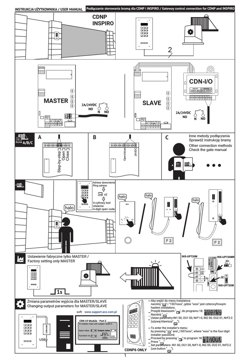
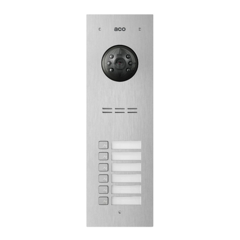
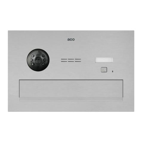
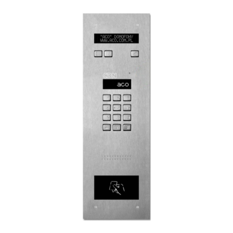
INSPIRO – installation manual for digital video door phone panels
Software v56
Applies to INSPIRO series 4, 6, , 8, 11, 15, 16
60-479 Poznań, Strzeszyńska 56, Poland, tel./ fax 061-8439-371
RULES FOR STORAGE OF USED ELECTRICAL EQUIPMENT
he used electrical equipment may not be stored together with other waste. Store it at
sites intended for this purpose. For this reason, address the responsible institutions or
companies dealing with waste recycling.
- Directive 2002/96/EC/ dated January 27th, 2003
MOUNTING
he panel must be mounted on the wall of the building, in a place where the impact of
unfavourable atmospheric conditions is minimal. We recommend the installation of the
panel at a height of about 1.35m.
he flush mounting box is mounted by means of expansion bolts and plaster in the right
hole in the wall. he front edge of the mounting box should be even with the wall surface.
ATTENTION! For the purpose of proper functioning as well as ensuring safety of use, the
panel (in a metal frame) must be connected at the installation site to the earthing,
connecting the earth terminal on the body with the appropriate protective installation (PE).
It is recommended to provide the connection between the panel and the electrical door
strike and the power supply convertor with the use of a wire with a cross section of 1 mm²
( e.g. LY1,0). he length of the wire should not exceed 7m in the case of an electrical
door strike circuit and 15m in the case of the power supply circuit!
In the case of smaller sections and too long connections, there may occur voltage drops
during opening of the electrical door lock, causing interferences in the operation of the
panel even after the opening operation is finished.
15V DC voltage from the video power supply (DR-45-15 recommended) to adder
terminals should be provided with a 3x1mm² cable.
In case of supplying the power from a buffer power supply with battery, the voltage 13,8V
should be connected to the adder's terminals.
he electrical door strike without specific polarisation is to be connected at will to
“ELOCK” terminals.
All the connections of the installation must be soldered!
he following wires are led to the panel:
• 3 power supply cores x 1mm²
• 2 cores x 1mm²– to the electrical door strike,
• 1 core of a wire in yellow-green insulation – to connect the enclosure earthing. U P
network cable (standard 568A or 568B) - busbar
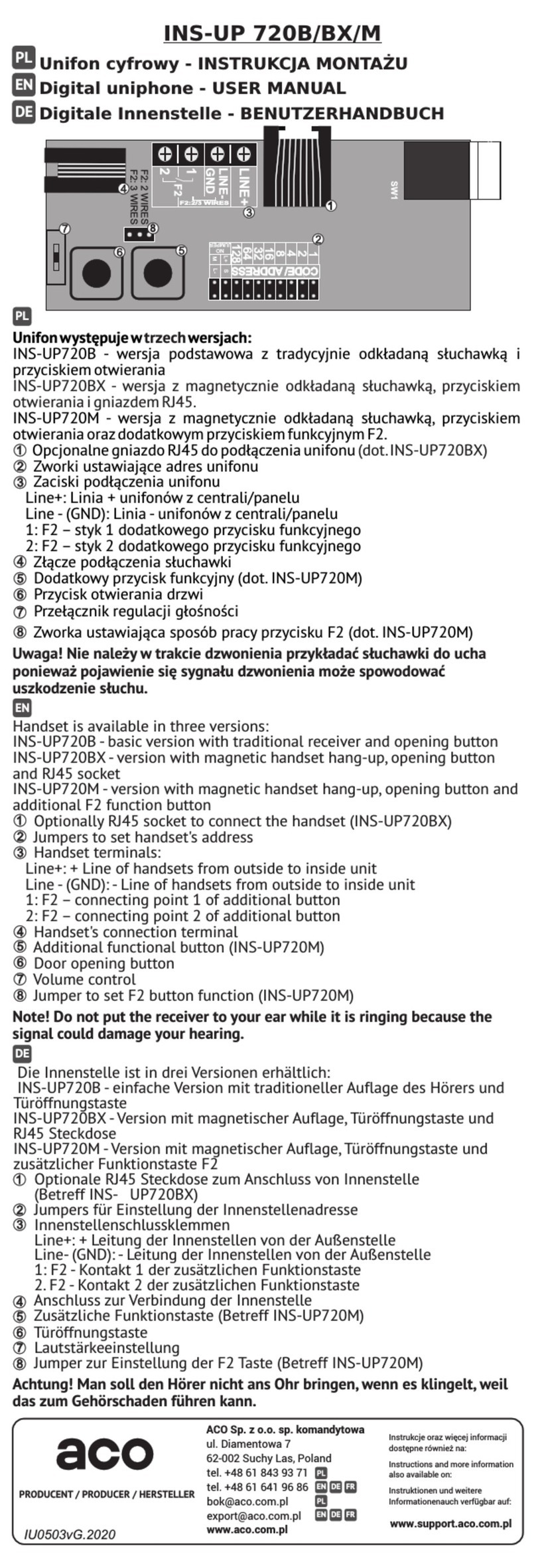
INSTALLATION AND CONNECTION OF THE UNIPHONES
he uniphones have to be installed in accordance with the installation manual of the
manufacturer. he connections shall be made paying particular attention to the number
setting in the uniphone decoder and proper (polarisation) connection to the “LINE”
terminals of the panel.
ADJUSTMENT OF THE SOUND LEVEL
he sound levels of the panel are set by the manufacturer, but for individual needs, they
may be adjusted. he volume level settings shall be made after obtaining the connection
with the uniphone in the following way:
-using the ”MIC” potentiometer, adjust the sound volume level in the uniphone handsets
from the panel's microphone (from the bottom),
- using the ”SPK” potentiometer, adjust the sound volume level in the loudspeaker of
the panel, coming from the uniphones in the premises (from above),
After setting these values, establish the position of points in which the excitation (beeping)
in the loudspeaker takes place by turning the ”BALANCE” with the potentiometer, and set
the potentiometer halfway between these points.
ELECTRICAL PARAMETER
•Power supply15V DC – (e.g., power supply DR-45-15)
•Power consumption max. 500mA
•Max. load for the electric strike out 1A
•Maximal installation length 70m – from the last power supply, total 300m – if using
additional power supplies.
CONNECTION DIAGRAM FOR ONE DEVICE
PROGRAMMING THE PANEL
In order to enter the installation programmes, press the ”key” button and enter an eight
digit password (1507xxxx) within 5 seconds confirmed by a sound signal modulated
“upward” and appearance of a message on the display „PROGR”. he first four digits of
the password (1507) are a constant value, and the next ones (”xxxx”) constitute the four-
digit password of the installer.
The password of the installer in a new panel is set to ”0000” and when the
installation is finished, it must be changed to a different password! (programme P7).
PROGRAMS OF THE PANEL:
SERVICE OPENING OF
THE ELECTRICAL DOOR
STRIKE
ZMIANA KODU OTWIERANIA
INDYWIDUALNEGO,
ADMINISTRATORA
SETTING QUIET OR LOUD
CALL
SETTING THE NUMBER
OF CALL RINGS,
PERMISSION TO CALL
THE PREMISES
SWITCHING ON –OFF THE
BELL-TINKLING TO A
PEMISES AFTER OPENING
THE DOOR
SERVICE CALL OF THE
UNIPHONE FROM THE
PREMISES
SETTING THE TIME FOR
CONTROL OF THE
ELECTRICAL DOOR
STRIKE
CHANGE IN THE
INSTALLERS’S
PASSWORD
CHECKING THE
CORRECTNESS OF
ASSIGNMENT OF THE
CARD TO THE PREMISES
CALL RANGE
PARAMETERS
SETTING THE SELECTION
OF NUMBERS IN THE
HOTEL SYSTEM
ENTERING THE NEW
TABLE OF OPENING
CODES
THE SELECTION OF THE
ADDITIONAL INPUT
FUNCTION
SETTING ONE OF FOUR
CALL SIGNALS
SEARCH FOR
IMPROPERLY HUNG UP
OR DAMAGED
UNIPHONES
THE ADDITIONALLY
SERVICED NUMBERS
SETTING THE
DOORPHONE PANEL
PARAMETERS
Bit1 - opening after corridor opening
expires
Bit2 - activation of the panel's
superior mode
Bit3 - activation of „dialling with
key” in hotel mode
Bit - activation of corridor opening
impulse
Bit5 - activation of dialling premise
number in hotel mode
Bit6 - changing direction of moving
the calling number (from p9
program)
Bit7 - activation of possibility to
change the opening code by the user
Bit8.- Blockage of factory reset
SETTING THE
DOORPHONE PANEL
PARAMETERS:
Bit1 - Choosing the camera for
preview when idle
Bit2 - Shortened (four digit) admin
opening code
Bit3 – doorman calling mode
Bit – doorman divert possibility
Bit5 - calling only for additional
numbers
Bit6 - Turning off the premise
number back light in module 230E
Bit7 – Calling parameters
Bit8 – activation of multi zone
system
THE PARAMETERS OF AN
ADDITIONAL
INPUT/OUTPUT MODULE
PROGRAMMING THE 30E
ELECTRONIC MODULE
FOR NAMES
PROGRAMMING THE
OPENING OF THE CDNACC
MODULE
PROGRAMMING THE
,6,10NP MODULES FOR
NAMES WITH BUTTONS
PROGRAMMING INTRO
ON THE DISPLAY
PROGRAMMING THE
TIME FOR SWITCHING ON
THE PHRASE „CALL
SERVICE”
PROGRAMMING THE
ADDITIONAL „FROM-TO”
RANGE
LINE TEST – CHECKING
THE HEADSETS IN THE
SYSTEM
Open OpKey
Hi-Lo Rings
OpInfo SfCall
LTime IPass
Cards Param
Hotel Tabel
Input Tones
Srch Add o
Bits1 Bits2
In/Out M230E
M-ACC M-Xnp
I TRO CServ
Range LTest

This manual suits for next models

6

Other ACO Intercom System manuals

ACO CDNP6ACC Installation instructions

ACO

ACO CDNP6ACC Installation instructions

ACO CDNP7ACC User manual

ACO

ACO CDNP7ACC User manual

ACO FAM-P Installation instructions

ACO

ACO FAM-P Installation instructions

ACO INSPIRO+VIDEO User manual

ACO

ACO INSPIRO+VIDEO User manual

ACO COMO-PRO-POST-A1 Series User manual

ACO

ACO COMO-PRO-POST-A1 Series User manual

ACO INS-UA720M User manual

ACO

ACO INS-UA720M User manual

ACO INS-UP 720B User manual

ACO

ACO INS-UP 720B User manual

ACO INSPIRO 1 Series User manual

ACO

ACO INSPIRO 1 Series User manual

ACO INSPIRO+audio User manual

ACO

ACO INSPIRO+audio User manual

ACO CDNP7ACC User manual

ACO

ACO CDNP7ACC User manual

ACO INS-UC 720M User manual

ACO

ACO INS-UC 720M User manual

ACO FAM-PV Series Installation instructions

ACO

ACO FAM-PV Series Installation instructions

ACO acoGO! P User guide

ACO

ACO acoGO! P User guide

ACO CDNP6ACC User manual

ACO

ACO CDNP6ACC User manual

ACO FAM-P Series User manual

ACO

ACO FAM-P Series User manual

ACO COMO-PRO User manual

ACO

ACO COMO-PRO User manual

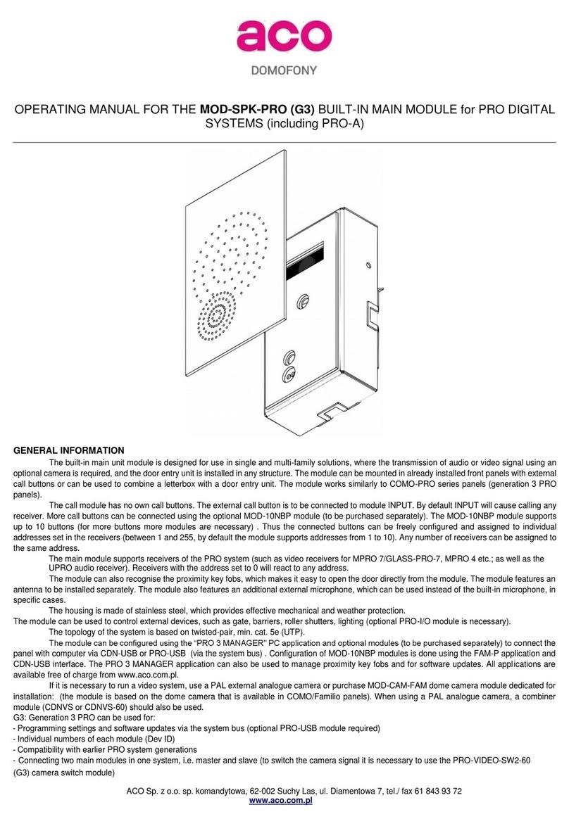
ACO MOD-SPK-PRO User manual

ACO

ACO MOD-SPK-PRO User manual

ACO CDNP6ACC User manual

ACO

ACO CDNP6ACC User manual

ACO FAM-P Series User manual

ACO

ACO FAM-P Series User manual

ACO COMO-PRO-V Series User manual

ACO

ACO COMO-PRO-V Series User manual

ACO Familio PRO User manual

ACO

ACO Familio PRO User manual

ACO GLASS-IP-7 User guide

ACO

ACO GLASS-IP-7 User guide

Popular Intercom System manuals by other brands

Swann Doorbell Video Intercom specification

Swann

Swann Doorbell Video Intercom specification

Aiphone MFW-P1 instructions

Aiphone

Aiphone MFW-P1 instructions

Studio Technologies 5421 user guide

Studio Technologies

Studio Technologies 5421 user guide

Comelit 1998V Technical manual

Comelit

Comelit 1998V Technical manual

golmar G2+ SOUL S5110/ART 7H instruction manual

golmar

golmar G2+ SOUL S5110/ART 7H instruction manual

Toa N-8050DS installation manual

Toa

Toa N-8050DS installation manual

ibood RVDP-GS Installation and operating instructions

ibood

ibood RVDP-GS Installation and operating instructions

urmet domus iPercom elekta steel 1060/23 user manual

urmet domus

urmet domus iPercom elekta steel 1060/23 user manual

urmet domus IPerCom VOG 7 1761 Series Booklet

urmet domus

urmet domus IPerCom VOG 7 1761 Series Booklet

Novi DB-301 installation guide

Novi

Novi DB-301 installation guide

Bpt HET/301 installation instructions

Bpt

Bpt HET/301 installation instructions

Aiphone KB-MV2 user manual

Aiphone

Aiphone KB-MV2 user manual

2easy DT 2-wire Technical guide

2easy

2easy DT 2-wire Technical guide

Fasttel WIZARD ELITE IP instruction manual

Fasttel

Fasttel WIZARD ELITE IP instruction manual

Alula CAM-DB-H2S-AI Quick setup

Alula

Alula CAM-DB-H2S-AI Quick setup

Aiphone LAF-20C instructions

Aiphone

Aiphone LAF-20C instructions

Tema Telecomunicazioni FXO Series Technical manual

Tema Telecomunicazioni

Tema Telecomunicazioni FXO Series Technical manual

Commax DR-2GN user manual

Commax

Commax DR-2GN user manual

manuals.online logo
manuals.online logoBrands
  • About & Mission
  • Contact us
  • Privacy Policy
  • Terms and Conditions

Copyright 2025 Manuals.Online. All Rights Reserved.