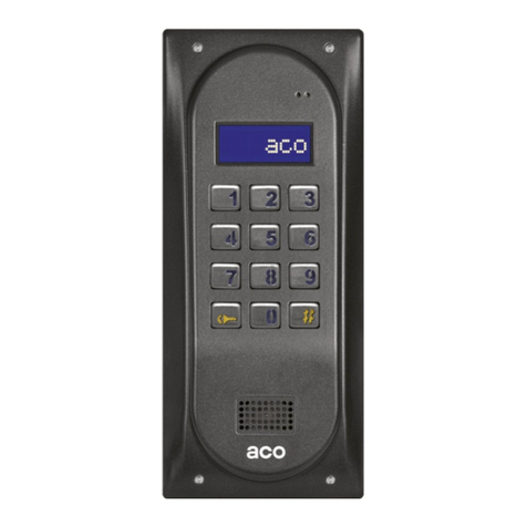
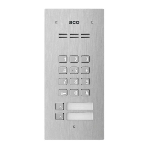
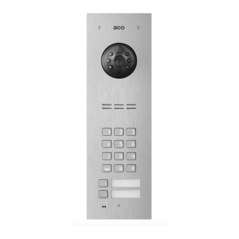
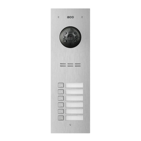
ACO CDNP6ACC User manual

RULES FOR STORAGE OF USED ELECTRICAL E UIPMENT
The used electrical equipment may not be stored together with other waste. Store it at sites intended for this purpose.
For this purpose, address the responsible institutions or companies dealing with waste recycling. - Directive
2002/96/EC/ dated January 27th, 2003
INSTALLATION OF THE DOORPHONE PANEL
The panel should be mounted on the wall of the building (entrance enclosure,vestibule, covered
wall, east wall etc.) so as to minimise the impact of unfavourableatmospheric conditions. We
recommend mounting the panel at the heigh of approx. 1.35m. The sheet metal of the base for
surface installation of the panel should bemounted to the surface using expansion bolts or
appropriate screws. The frame ofthe concealed installation of the panel should be mounted using
expansion bolts and gypsum in the wall opening. The wires need to be pulled through the openings
in the base.NOTE! To ensure correct functioning as well as the safety of use, the panel (in a metal
frame) must be connected at the installation site tothe earthing, connecting the earth terminal on
the body with the appropriateprotective installation (PE).It is recommended to provide the
connection between the panel and the electrical door strike and the power supply transformer
using a wire of 1 mm2 in diameter ( e.g. Y1,0). The length of the wire should not exceed 7m in the
case of an electrical door strike circuitand 15 m in the case of the power supply circuit! In the case
of smaller diameters and too long connections, voltage drops may occur during opening of the
electrical door lock, causing interferences in the operation of the panel or activation of reset
function and restart of the unit, especially during opening procedure. Supply voltage 11,5V AC
should be connected to the main panel's 12V~ clamps. In case you are using 15V DC connect the
voltaeg to the clamps +DC (+E OCK) and GND ( INE-). For video systems use only direct current
power supply 15V DC and connect it to the combiner’s terminals. E-lock without estimated
polarisation connects freely to „E OCK” clamps. When using reverse e-lock put jumper Z13 (under
resistor on the left side of the pcb)!If you work with reverse elock there will be supply voltage at
“E OCK” terminal and use appropriate reverse elock type compatible with the provided voltage.
You can also use MOD-DC-12V module which will supply 12VDC to the reverse elock if you are
using 15VDC power supply or transformer.
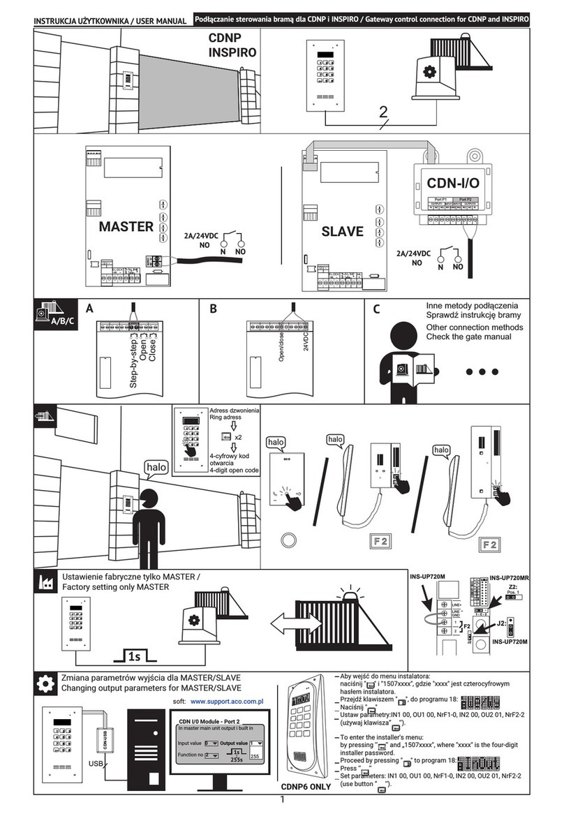
Additional relay output "OUTPUT" (only Master) can be used to control, for example, another gate
(factory setting) by means of a code (with "double key") and handset’s F2 button. Operation time
and functions of the "OUTPUT" can be changed in program 18, port 2 (in the same way as the
CND-I / O module).
All connections in the installation must be soldered!
The following wires should be connected to the installation:
•2 wires x 1mm2 - transformer power supply,
•2 wires x 1mm2 - for the electric door strike,
•2 wires x 0,5mm panel wire to connect the uniphones.
•1 yellow-green insulated wire - to connect the panel housing earthing
SINGLE CDNP OUTSIDE UNIT WIRING DIAGRAM
TWO & MORE CDNP OUTSIDE UNITS WIRING DIAGRAM
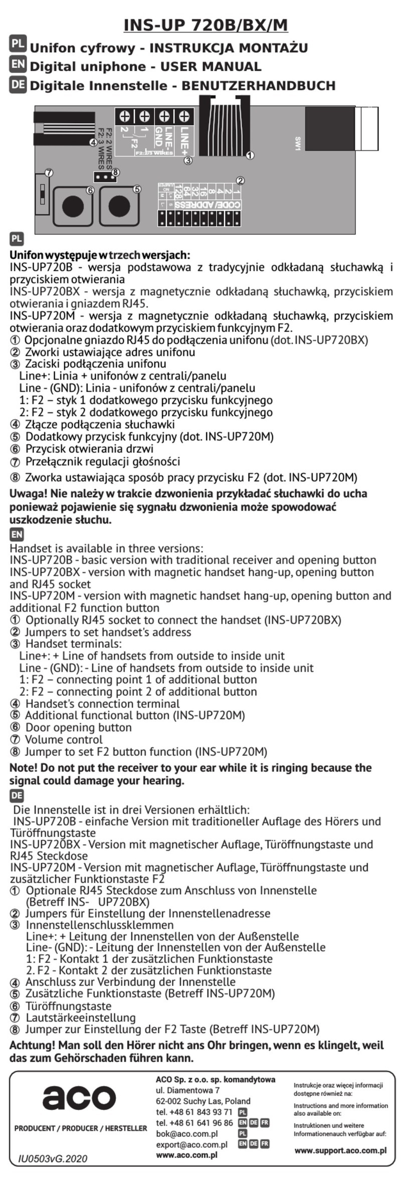
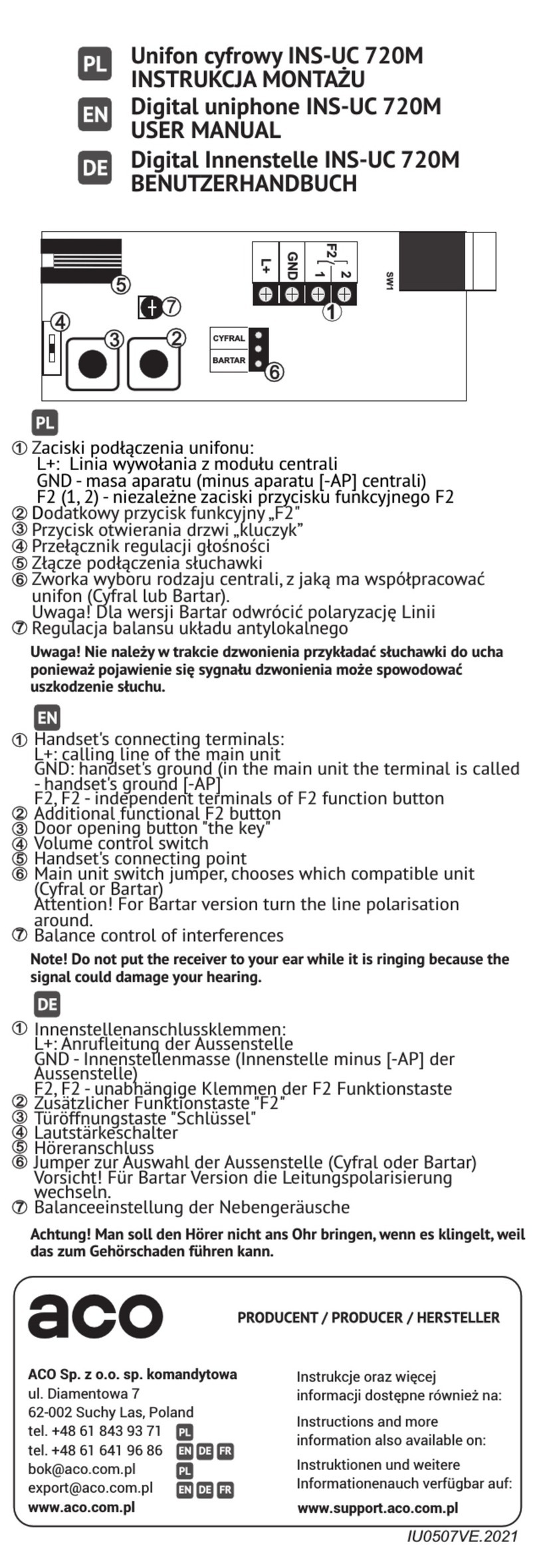
MOUNTING AND CONNECTING UNIPHONES
Uniphones should be connected according to the installation manual. The connections should be made with
paying particular attention to the settings numbers in the uniphone decoder and proper (polarisation)
connection to the “ INE”terminals of the panel.
ADJUSTING SOUND VOLUME
The volume level settings shall be made after obtaining the connection with the uniphonein the following
way:
- the ”MIC” knob, adjusts the panel's microphone sound volume
- the ”SPK” knob, adjusts the speaker's microphone sound volume
- the ”SOUNDS” knob, adjusts the panel's sound volume
After setting these values, establish the position of points in which the excitation (beeping)in the
loudspeaker takes place by turning the ”BA ANCE” with the potentiometer, and set the potentiometer
halfway between these points.
OPERATION
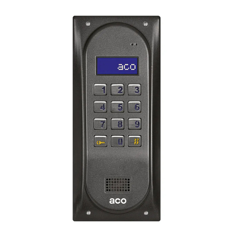
When idle, "Intro" is displayed on the screen ("aco" by default). "Intro" can be changed as desired. By
default, we can call numbers from 1 to 255, which corresponds directly to the physical adresses set in the
receivers (we can switch dialing numbers from the keypad from 1 to 999, maintaining the continuity of
physical addresses from 1 to 255). Calling is by selecting the apartment number using the keypad buttons
or if the 230E module is present, you can select the entry with the "arrows" and press the "bell" button. After
approx. 3 seconds the receiver in the selected apartment will ring. If the call is answered in the ring mode,
you can talk and open the door. Opening the door with the user (tenant) code consists in using the
keyboard to select the apartment number to which the code is assigned, confirming with the "key" button
and selecting the four-digit code. In order to print the full table of user codes or ready business cards for
tenants together with the instructions for use, use the "ACO Code Generator" available at www.aco.com.pl
in the user area ("download"). For each "Master" control panel, the code table is factory-set on the back of
the device as a 4-digit number, and for "Slave" devices, enter the same table as in "Master". Opening the
administrator code consists in selecting the "key" button followed by a six-digit code. The administrator code
is intended for building’s administrators, e.g. technical services, postmen, house owners, etc. The door will
also be opened after shorting the additional INPUT to ground. For devices equipped with the ACC proximity
reader (CDNP6ACC), opening will occur after presenting the proximity card or proximity tag (tenant or
administrator / installer) stored in the device. If the card / key fob is not stored, you will hear a triple "beep"
in the speaker. When opening the door, the display shows "Enter!" Activation of the OUTPUT (only Master)
will take place after pressing the F2 button on the receiver (during the conversation) or after entering the
user code - press the "key" twice before entering the same code as for basic opening. When using ACC, the

second output will be activated by pressing the "key" button and presenting the proximity card or key fob
stored into the device. While the output is active, the display will show "Out-2".
PROGRAMMING
Entering the installer menu: press the "key" button and enter "1507xxxx" within 5 seconds, where "xxxx" is
the four-digit Installer Password, which is factory set to "0000" and must be changed to your own! (menu 7 -
the current password must be entered again first). Confirmation of entering the installer menu is a sound si-
gnal, the appearance of the software version on the display and then the program number 0: "Open". The
menu is changed with the buttons "2" up and "8" down. Enter the currently displayed menu and entering val-
ues is confirmed by pressing the "Key" button. In the installer mode, it is possible to reset (restart) the panel
by pressing simultaneously buttons 7 and 9. While exiting the installer menu (by pressing the "#" button),
the current temperature inside the control panel is displayed.
CDNP Panel programs:
SERVICE OPENING OF THE
ELECTRICAL DOOR STRIKE
CHANGE IN THE INDIVIDUAL
OPENING CODE OF THE
ADMINISTRATOR
SETTING QUIET OR LOUD CALL
SETTING THE NUMBER OF CALL
RINGS, PERMISSION TO CALL
THE PREMISES
SWITCHING ON –OFF THE BELL-
TINKLING TO A PEMISES AFTER
OPENING THE DOOR
SERVICE CALL OF THE
UNIPHONE FROM THE PREMISES
SETTING THE TIME FOR
CONTROL OF THE ELECTRICAL
DOOR STRIKE
CHANGING THE FITTER’S
PASSWORD
CHECKING THE CORRECTNESS
OF ASSIGNMENT OF THE CARD
TO THE PREMISES
CALL RANGE PARAMETERS
SETTING THE SELECTION OF
NUMBERS IN THE HOTEL
SYSTEM
ENTERING THE NEW TABLE OF
OPENING CODES
SELECTION OF THE ADDITIONAL
INPUT FUNCTION SETTING ONE
OF FOUR CALL SIGNALS
SEARCH FOR IMPROPERLY
HUNG UP OR DAMAGED
UNIPHONES
THE ADDITIONALLY SERVICED
NUMBERS
Bits1
SETTING THE PANEL
PARAMETERS
Bit1 - Activating opening after corridor
opening time-out
Bit2 - Input function in the slave panel
Bit3 - Activation an optional additional
electronic module
Bit4 - Activating corridor opening
impulse
Bit5 - Activating number dialling in the
hotel system
Bit6 - hanging the direction of calling
number diversion (from the P9
programme)
Bit7 - Activating code change function
for the user
Bit8 - Blocking factory reset function
Bits2
SETTING THE PANEL
PARAMETERS
Bit1 - hoosing the preview camera in
standby mode
Bit2 - Short (four digit) administrator's
opening code
Bit3 - Porter calling
Bit3 - Porter redirection
Bit5 - Only calling for additional
numbers
Bit6 - Disable premise number display in
230E module
(from software v4.1)
Bit7 - Activating reverse eletric door
strike
Bit8 – compatible with multi master
module
THE PARAMETERS OF AN
ADDITIONAL INPUT/OUTPUT
MODULE
PROGRAMMING THE 23 E
ELECTRONIC MODULE FOR
NAMES Beginning from the version
7.00 programming only via computer
PROGRAMMING THE ACC
PROXIMITY MODULE
PROGRAMING THE NAME
MODULE
2,6,1 NP WITH BUTTONS
PROGRAMMING INTRO ON THE
DISPLAY
PROGRAMMING THE TIME FOR
SWITCHING ON THE PHRASE
„CALL SERVICE”
PROGRAMMING THE
ADDITIONAL „FROM-TO” RANGE
LINE TEST – CHECKING
THE HEADSETS IN THESYSTEM
ATTENTION! Full control panel configuration is possible by means of computer software ("CDNP") for free download
from www.aco.com.pl. An optional CDN-USB cable is required to connect the control panel to a computer. You can
also download the extended CDNP operating instructions along with a description of common problems from the site.
IU0404enVE.1938
Open OpKey
Hi-Lo Rings
OpInf SfCal
LTime IPass
Cards Param
Hotel Table
Input Tones
Sr h AddNo
InOut M230E
M-ACC M-Xnp
INTRO CServ
Range LTest
Param
Other manuals for CDNP6ACC
2
This manual suits for next models
1
Other ACO Intercom System manuals

ACO
ACO acoGO! P User guide

ACO
ACO Familio PRO User manual

ACO
ACO GLASS-IP-7 User guide

ACO
ACO CDNP6ACC Installation instructions

ACO
ACO MOD-SPK-PRO User manual

ACO
ACO CDNP7ACC User manual

ACO
ACO INSPIRO+VIDEO User manual

ACO
ACO FAM-P Series User manual

ACO
ACO CDNP7ACC User manual

ACO
ACO COMO-PRO-POST-A1 Series User manual

ACO
ACO FAM-P Installation instructions

ACO
ACO INS-UA720M User manual

ACO
ACO INSPIRO 1 Series User manual

ACO
ACO COMO-PRO User manual

ACO
ACO INS-UC 720M User manual

ACO
ACO FAM-P Series User manual

ACO
ACO INSPIRO+audio User manual

ACO
ACO CDNP6ACC User manual

ACO
ACO COMO-PRO-V Series User manual

ACO
ACO FAM-PV Series Installation instructions