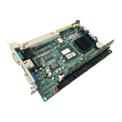
v AIMB-592 User Manual
Contents
Chapter 1 General Information ............................1
1.1 Introduction ............................................................................................... 2
1.2 Features.................................................................................................... 2
1.3 Specifications............................................................................................ 2
1.3.1 Processor...................................................................................... 2
1.3.2 Memory......................................................................................... 2
1.3.3 Input/Output .................................................................................. 2
1.3.4 Graphics........................................................................................ 2
1.3.5 Ethernet LAN ................................................................................ 2
1.3.6 Industrial Features ........................................................................ 3
1.3.7 Mechanical and Environmental Specifications.............................. 3
1.4 Jumpers and Connectors .......................................................................... 3
1.5 Board layout: Jumper and Connector Locations ....................................... 3
Figure 1.1 Board Layout .............................................................. 3
Figure 1.2 Rear I/O of the Two SKUs .......................................... 4
Table 1.1: Jumper Setting List..................................................... 4
Table 1.2: Connector / Header List:............................................. 4
1.6 AIMB-592 Board Diagram ......................................................................... 6
Figure 1.3 AIMB-592 Board Diagram .......................................... 6
1.7 Safety Precautions.................................................................................... 6
1.8 Jumper Settings ........................................................................................ 7
1.8.1 How to Set Jumpers...................................................................... 7
1.8.2 CMOS Clear (JCMOS1)................................................................ 7
Table 1.3: JCMOS1 ..................................................................... 7
1.9 System Memory ........................................................................................ 7
1.10 Memory Installation Procedures................................................................ 7
1.11 Processor Installation................................................................................ 8
Chapter 2 Connecting Peripherals ....................13
2.1 Introduction ............................................................................................. 14
2.2 LAN and USB Ports (LAN1_USB12/ LAN2_USB34/ LAN3_4/LAN5) ..... 14
2.3 VGA and Serial Ports (VGA1/COM1)...................................................... 15
2.4 BMC ROM socket (BMC_SKT1) ............................................................. 15
2.5 BIOS SPI ROM socket (BIOS_SKT1) ..................................................... 16
2.6 Battery Holder (BAT1)............................................................................. 16
2.7 LPC Connector (LPC1) ........................................................................... 17
2.8 PCIe Expansion Slot (PCIEX16_SLOT1/ PCIEX16_SLOT2/
PCIEX16_SLOT3/ PCIEX16_SLOT4)..................................................... 17
2.9 System Error LED wafer (BMC_SYSLED1)............................................ 18
2.10 PMBus wafer (PMBUS1)......................................................................... 19
2.11 Hardware SMBUS (SMBUS1)................................................................. 19
2.12 Front Panel3 (JFP3)................................................................................ 20
2.13 Graphics Card 12V slot (PCIE_SLOT12V1) ........................................... 20
2.14 System FAN Connector (SYSFAN1/SYSFAN2/SYSFAN3/SYSFAN4) .. 21
2.15 Serial General Purpose I/O Connector (SGPIO1)................................... 23
2.16 Serial ATA Interface Connector (SATA1~8)............................................ 23
2.17 CPU Fan Connector (CPUFAN1)............................................................ 24
2.18 NGFF M.2 M-Key (NGFF_M1)................................................................ 25
2.19 Slimline SAS 4i Connector (SAS1/SAS2) ............................................... 25
2.20 General purpose I/O Connector (GPIO1)................................................ 26
2.21 USB3.2 Gen1 vertical connector (USB5) ................................................ 26
2.22 DDR4 RDIMM slot (DIMME1/ DIMMH1/ DIMMG1/ DIMMA1/ DIMMD1/
DIMMC1)................................................................................................. 27


