manuals.online logo
Brands
  1. Home
  2. •
  3. Brands
  4. •
  5. Advantech
  6. •
  7. Computer Hardware
  8. •
  9. Advantech PCL-734 User manual

Advantech PCL-734 User manual

Other manuals for PCL-734

1

Other Advantech Computer Hardware manuals

Advantech APAX-5070 User manual

Advantech

Advantech APAX-5070 User manual

Advantech PCA-6154 Installation and operation manual

Advantech

Advantech PCA-6154 Installation and operation manual

Advantech UNO-238 V2 User manual

Advantech

Advantech UNO-238 V2 User manual

Advantech PCE-7B13-0AA1 Installation and operation manual

Advantech

Advantech PCE-7B13-0AA1 Installation and operation manual

Advantech PCE-3B06-02 Installation and operation manual

Advantech

Advantech PCE-3B06-02 Installation and operation manual

Advantech MIC-75G20-10A2 Installation and operation manual

Advantech

Advantech MIC-75G20-10A2 Installation and operation manual

Advantech PCIE-1753 User manual

Advantech

Advantech PCIE-1753 User manual

Advantech SKY-MXM-A1000 User manual

Advantech

Advantech SKY-MXM-A1000 User manual

Advantech MIC-3365 User manual

Advantech

Advantech MIC-3365 User manual

Advantech PCM-26R1EC User manual

Advantech

Advantech PCM-26R1EC User manual

Advantech ASMB-935 Series User manual

Advantech

Advantech ASMB-935 Series User manual

Advantech MIC-3820 Installation and operation manual

Advantech

Advantech MIC-3820 Installation and operation manual

Advantech PCIe-1674 User manual

Advantech

Advantech PCIe-1674 User manual

Advantech PCM-3718H User manual

Advantech

Advantech PCM-3718H User manual

Advantech PCE-5B05V-30B1E Installation and operation manual

Advantech

Advantech PCE-5B05V-30B1E Installation and operation manual

Advantech MIO-5376 User manual

Advantech

Advantech MIO-5376 User manual

Advantech PCL-818L User manual

Advantech

Advantech PCL-818L User manual

Advantech MIO-9290 User manual

Advantech

Advantech MIO-9290 User manual

Advantech PCIE-1158 Installation and operation manual

Advantech

Advantech PCIE-1158 Installation and operation manual

Advantech UNO-238 V2 Installation and operation manual

Advantech

Advantech UNO-238 V2 Installation and operation manual

Advantech ASMB-830 Series User manual

Advantech

Advantech ASMB-830 Series User manual

Advantech PCA-6190 User manual

Advantech

Advantech PCA-6190 User manual

Advantech PCL-818 Series User manual

Advantech

Advantech PCL-818 Series User manual

Advantech VEGA-2002 User manual

Advantech

Advantech VEGA-2002 User manual

Popular Computer Hardware manuals by other brands

Toshiba TOSVERT VF-MB1/S15 IPE002Z Function manual

Toshiba

Toshiba TOSVERT VF-MB1/S15 IPE002Z Function manual

Shenzhen MEITRACK MVT380 user guide

Shenzhen

Shenzhen MEITRACK MVT380 user guide

TRENDnet TEW-601PC - SUPER G MIMO WRLS PC CARD user guide

TRENDnet

TRENDnet TEW-601PC - SUPER G MIMO WRLS PC CARD user guide

StarTech.com CF2IDE18 instruction manual

StarTech.com

StarTech.com CF2IDE18 instruction manual

Texas Instruments LMH0318 Programmer's guide

Texas Instruments

Texas Instruments LMH0318 Programmer's guide

Gateway 8510946 user guide

Gateway

Gateway 8510946 user guide

Devon IT TC2D Quick setup guide

Devon IT

Devon IT TC2D Quick setup guide

Krüger & Matz Air Shair2 owner's manual

Krüger & Matz

Krüger & Matz Air Shair2 owner's manual

Crystalio VPS-2300 quick guide

Crystalio

Crystalio VPS-2300 quick guide

MYiR FZ3 user manual

MYiR

MYiR FZ3 user manual

Protech Systems BC-K200 Quick reference guide

Protech Systems

Protech Systems BC-K200 Quick reference guide

Miranda DENSITE series DAP-1781 Guide to installation and operation

Miranda

Miranda DENSITE series DAP-1781 Guide to installation and operation

Sierra Wireless Sierra Wireless AirCard 890 quick start guide

Sierra Wireless

Sierra Wireless Sierra Wireless AirCard 890 quick start guide

Leadtek Killer Xeno Pro Quick installation guide

Leadtek

Leadtek Killer Xeno Pro Quick installation guide

Star Cooperation FlexTiny 3 Series Instructions for use

Star Cooperation

Star Cooperation FlexTiny 3 Series Instructions for use

Hotone Ampero user manual

Hotone

Hotone Ampero user manual

Connect Tech Xtreme/104-Express user manual

Connect Tech

Connect Tech Xtreme/104-Express user manual

Yealink WF50 user guide

Yealink

Yealink WF50 user guide

manuals.online logo
manuals.online logoBrands
  • About & Mission
  • Contact us
  • Privacy Policy
  • Terms and Conditions

Copyright 2025 Manuals.Online. All Rights Reserved.

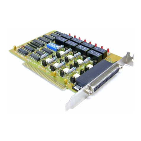
PCL-734
32-channel Isolated
Digital Output Card
Copyright
This documentation is copyrighted 1996 by Advantech Co., Ltd. All
rights are reserved. Advantech Co., Ltd. reserves the right to make
improvements in the products described in this manual at any time
without notice.
No part of this manual may be reproduced, copied, translated or
transmitted in any form or by any means without the prior written
permission of Advantech Co., Ltd. Information provided in this
manual is intended to be accurate and reliable. However, Advantech
Co., Ltd. assumes no responsibility for its use, nor for any infringe-
ments of the rights of third parties which may result from its use.
Acknowledgments
PC-LabCard is a trademark of Advantech Co., Ltd. IBM and PC are
trademarks of International Business Machines Corporation. MS-
DOS, Microsoft C and Quick BASIC are trademarks of Microsoft
Corporation. BASIC is a trademark of Dartmouth College. Intel is a
trademark of Intel Corporation. TURBO C is a trademark of Borland
International.
Part No. 2003734000 1st Edition
Printed in Taiwan April 1996
Contents
Chapter 1 General information ........................................ 1
IntroductionIntroduction
Introduction ..............................................................
..............................................................
............................... 22
22
2
FeaturesFeatures
FeaturesFeatures
Features ....................................................................
....................................................................
.................................. 22
22
2
ApplicationsApplications
Applications ..............................................................
..............................................................
............................... 22
22
2
SpecificationsSpecifications
Specifications ............................................................
............................................................
.............................. 33
33
3
Digital output ................................. 3
Register format ................................ 3
Dimensions ................................... 3
Connectors ................................... 3
Power consumption ............................. 3
DaughterboardsDaughterboards
Daughterboards ........................................................
........................................................
............................ 33
33
3
Chapter 2 Installation........................................................ 5
Initial inspectionInitial inspection
Initial inspection ........................................................
........................................................
............................ 66
66
6
Switch and jumper settingsSwitch and jumper settings
Switch and jumper settings ........................................
........................................
.................... 66
66
6
Base address selection (SW1) ...................... 6
Hardware installationHardware installation
Hardware installation ................................................
................................................
........................ 99
99
9
Installing the card in your computer ................... 9
Chapter 3 Signal connections ........................................ 11
Connector pin assignmentsConnector pin assignments
Connector pin assignments ........................................
........................................
.................... 1212
1212
12
Isolated OutputIsolated Output
Isolated Output ........................................................
........................................................
............................ 1313
1313
13
Chapter 4 Register format ............................................. 15
Appendix A PC I/O port address map ............................ 17
Chapter 1 General information 11
11
1
1
General information
CHAPTER
22
22
2 PCL-734 User's Manual
Introduction
The PCL-734 offers 32 isolated digital output channels on a PC add-
on card. Its isolated output channels provide 1,000 V of protection.
Each I/O channel corresponds to a bit in a PC I/O port. This makes the
PCL-734 very easy to program.
Features
• 32 isolated digital output channels
• High output driving capacity
• High-voltage isolation on isolated output channels (1,000 VDC)
• Open collector outputs (up to 40 VDC)
• D-type connectors for isolated output channels
• High sink current on isolated output channels (200 mA/channel)
• Suppression diode for inductive loads
Applications
• Industrial ON/OFF control
• Contact closure monitoring
• Switch status sensing
• BCD interfacing
• Digital I/O control
• Industrial and lab automation
Chapter 1 General information 33
33
3
Specifications
Digital output
32 optically-isolated outputs
••
••
•Output voltageOutput voltage
Output voltageOutput voltage
Output voltage: Open collector 5 to 40 VDC
••
••
•Sink currentSink current
Sink currentSink current
Sink current: 200 mA max.
••
••
•Isolation voltageIsolation voltage
Isolation voltageIsolation voltage
Isolation voltage: 1,000 VDC
Register format
BASE+0 Isolated DO0~DO7
BASE+1 Isolated DO8~DO15
BASE+2 Isolated DO16~DO23
BASE+3 Isolated DO24~DO31
Dimensions
185 mm x 100 mm
Connectors
DB-37 connector for isolated Digital Output
Power consumption
+5 V: 330 mA typical, 500 mA maximum
Daughterboards
PCLD-880
The PCLD-880 is a universal screw terminal board for industrial
wiring. It can be used with the analog or digital ports of various PC-
LabCards via 20-pin flat cables or shielded round cables with DB-37
connectors.
Chapter 2 Installation 55
55
5
CHAPTER
2
Installation
66
66
6 PCL-734 User's Manual
Initial inspection
We carefully inspected the PCL-734 both mechanically and electrical-
ly before shipment. It should be free of marks and in perfect order on
receipt.
As you unpack the PCL-734, check it for signs of shipping damage
(damaged box, scratches, dents, etc.). If it is damaged or fails to meet
specifications, notify our service department or your local sales
representative immediately. Also, call the carrier immediately and
retain the shipping carton and packing material for inspection by the
carrier. We will then make arrangements to repair or replace the unit.
Discharge any static electricity on your body before you touch the
board by touching the back of the system unit (grounded metal).
Remove the PCL-734 card from its protective packaging by grasping
the rear metal panel. Handle the card only by its edges to avoid static
electric discharge which could damage its integrated circuits. Keep the
antistatic package. Whenever you remove the card from the PC, please
store the card in this package for protection.
You should also avoid contact with materials that hold static electricity
such as plastic, vinyl and styrofoam.
Switch and jumper settings
The PCL-734 card has one function switch and three jumper settings.
The following sections tell how to configure the card. You may want
to refer to the opposite page for help identifying card components.
Base address selection (SW1)
You control the PCL-734's operation by writing data to the PC's I/O
(input/output) port addresses. The PCL-734 requires four consecutive
address locations. Switch SW1 sets the card's base (beginning)
address. Valid base addresses range from Hex 200 to Hex 3F0.
However, other devices in your system may be using some of these
addresses.
Chapter 2 Installation 77
77
7
LabelLabel
LabelLabel
Label FunctionFunction
FunctionFunction
Function
CN1CN1
CN1CN1
CN1 Isolated output
CN2CN2
CN2CN2
CN2 E.GND (external ground)
SW1SW1
SW1SW1
S W 1 Card base address
Card connector, jumper and switch locationsCard connector, jumper and switch locations
Card connector, jumper and switch locations
88
88
8 PCL-734 User's Manual
We set the PCL-734 for a base address of Hex 300 at the factory. If
you need to adjust it to some other address range, set switch SW1 as
shown in the following table:
Card I/O addresses (SW1)
Range (hex)Range (hex)
Range (hex) Switch positionSwitch position
Switch positionSwitch position
Switch position
12345678
200 - 203 ¡lllllll
204 - 207 ¡llllll¡
´
*300 - 303 ¡¡llllll
´
3F0 - 3F3 ¡¡¡¡¡¡l l
¡= Off l= On *= default
Note:Note:
Note:Note:
Note: Switches 1-8 control the PC bus address lines as shown
below:
SwitchSwitch
SwitchSwitch
Switch 1 2 3 45678
LineLine
LineLine
Line A 9 A 8 A 7 A 6 A 5 A 4 A 3 A 2
Appendix A provides a PC I/O port address map to help you avoid the
I/O addresses for standard PC devices.