ix iDAQ-817_821 User Manual
Contents
Chapter 1 Start Using iDAQ-817/821 ...................1
1.1 Overview ................................................................................................... 2
1.2 Product Overview...................................................................................... 2
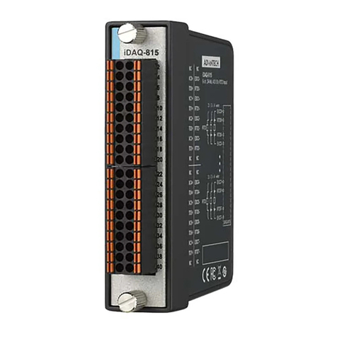
Figure 1.1 Overview of iDAQ-817................................................ 2
Figure 1.2 Overview of iDAQ-821................................................ 2
1.3 Product Features....................................................................................... 3
1.3.1 Power Input................................................................................... 3
1.3.2 BoardID......................................................................................... 3
1.3.3 Plug and Play Device.................................................................... 3
1.4 Driver Installation ...................................................................................... 3
Figure 1.3 XNavi Installation Interface......................................... 3
1.5 Software Utility .......................................................................................... 4
1.6 Software Development Using DAQNavi SDK ........................................... 4
1.7 Application Software DAQNavi MCM........................................................ 4
1.8 FPGA Code Update .................................................................................. 4
1.9 Ordering Information ................................................................................. 4
Chapter 2 Installation Guide ................................5
2.1 Initial Unpacking Check............................................................................. 6
2.2 Installation ................................................................................................. 6
Figure 2.1 iDAQ Module Install into iDAQ Chassis...................... 6
2.3 Signal Connection and Pin Assignment.................................................... 7
2.3.1 Analog Input Connection............................................................... 7
Figure 2.2 Analog input signal connection................................... 7
Figure 2.3 Common-mode input voltage. .................................... 7
2.3.2 Analog Output Connection............................................................ 8
Figure 2.4 Analog output signal connection................................. 8
2.3.3 Pin Assignment............................................................................. 9
Figure 2.5 Pin Assignment for iDAQ-817..................................... 9
Table 2.1: Pin Assignment for iDAQ-817..................................... 9
Figure 2.6 Pin Assignment for iDAQ-821..................................... 9
Table 2.2: Pin Assignment for iDAQ-821..................................... 9
Chapter 3 Function Details.................................11
3.1 Function Details ...................................................................................... 12
3.2 Analog Input............................................................................................ 12
3.2.1 Instant Analog Input Acquisition.................................................. 12
Figure 3.1 Instant analog input acquisition. ............................... 12
3.2.2 Buffered Analog Input Acquisition............................................... 12
Figure 3.2 Buffered analog input acquisition. ............................ 13
Figure 3.3 Start and stop triggers of the analog input acquisition..
13
Figure 3.4 Start and stop of the analog input acquisition with de-
lay. ............................................................................ 14
3.2.3 High Common-Mode Amplifier.................................................... 14
Figure 3.5 Common-mode input voltage. .................................. 14
3.2.4 Analog Input Low-pass Filter ...................................................... 14
3.2.5 Analog Multiplexer ...................................................................... 15
3.2.6 Analog Input Isolation ................................................................. 15
3.3 Analog Output ......................................................................................... 15
3.3.1 Static Analog Output Update ...................................................... 15
