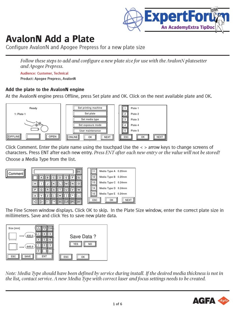
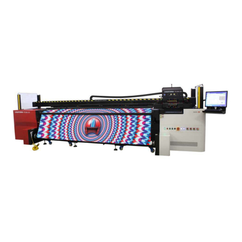
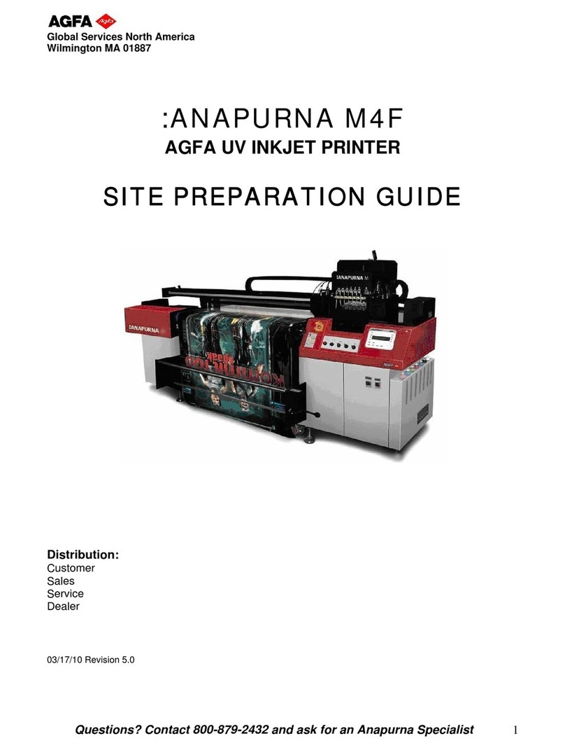
AGFA ANAPURNA M4F User manual

ab
Operator Manual
:Anapurna M4F
(FW version 1.979)
Stay ahead with Agfa Global Services. Operator Manual

:Anapurna M4F Operator Manual
(FW version 1.979 rev. 20080808)
Any remarks and/or suggestions on the content of this
operator manual can be send to:
©Agfa Graphics NV. - Belgium

Stay ahead. With Agfa Global Services. :Anapurna M4F - Operator Manual
Index 3
Index
A. INFORMATION.
1. Safety instructions. .............................................................................................................. 5
1.1 Warning labels............................................................................................................ 5
1.2 Emergency switches. ................................................................................................. 6
1.3 Optical safety sensors. .............................................................................................. 6
1.4 U.V. light....................................................................................................................... 7
a. Detail of the UV light......................................................................................... 7
1.5 U.V. inks........................................................................................................................ 8
a. Curing Process..................................................................................................... 8
1.6 Extra information........................................................................................................ 8
2. Printer overview.................................................................................................................... 9
2.1 Front view, parts & locations. .................................................................................. 9
2.2 Home view, parts & locations.................................................................................. 9
2.3 Capping station view, parts & locations.............................................................. 10
2.4 Head carriage view, parts & locations.................................................................. 10
2.5 Rearside view, parts & locations........................................................................... 10
B. OPERATIONS.
1. Makingyourrstprint....................................................................................................... 11
1.1 Wasatch SoftRIP: setting up your image............................................................. 11
1.2 Starting up the :Anapurna M4F.............................................................................. 11
1.3 Makingyourrstprint............................................................................................. 12
2. The Wasatch SoftRIP 6.4 AE............................................................................................. 13
2.1 Main Window - overview........................................................................................ 13
a. Menu items........................................................................................................ 13
b. Universal Controls. ........................................................................................... 14
c. Top tabs............................................................................................................... 14
d. Left tabs.............................................................................................................. 14
2.2 Open an image.......................................................................................................... 15
2.3 Cropping, resizing an image................................................................................... 15
a. Resizing. ............................................................................................................. 15
b. Cropping. ............................................................................................................ 15
c. Restore Original View. ..................................................................................... 16
d. Rotating. ............................................................................................................. 16
e. Mirroring. ............................................................................................................ 17
2.4 Choosinganimagingconguration...................................................................... 17
2.5 Ripping and printing the image............................................................................. 17
3. The operator panel. (general overview) ......................................................................... 19
4. Start up & Shutdown Procedures. ................................................................................... 20
4.1 Start up Procedure ................................................................................................... 20
4.2 Making the engine ready for Printing. ................................................................. 20
4.3 Shutdown Procedures.............................................................................................. 21
a. Dialy Shut Down Procedure............................................................................ 21
b. Weekly Shut Down Procedure........................................................................ 21
c. Long Stand Still Shut Down Procedure (More than 14 days) ................... 21
5. Setting up the :Anapurna M4F. (the calibration menu)............................................... 23
5.1 Feed Adjust (F1)........................................................................................................ 23
5.2 Carriage Release (F2). .............................................................................................. 23
5.3 Factory setting (F3). ................................................................................................. 23
5.4 Hori. Adjust (F4). ....................................................................................................... 23
5.5 Dir. Adjust (F4)........................................................................................................... 24
5.6 Head Gap (F6). ........................................................................................................... 24
5.7 Importance of the bi-directional alignment........................................................ 26
6. Changing the parameters. (the main menu).................................................................. 28
6.1 Information bar. ........................................................................................................ 28
6.2 Function keys (parameters). ................................................................................... 29
6.3 Media setup. (rigids and roll to roll) ..................................................................... 33
a. Rigid media........................................................................................................ 33
b. Roll media. ......................................................................................................... 34
c. Vacuum system................................................................................................. 36
:Anapurna M4F - Operator Manual Stay ahead. With Agfa Global Services.
4 Index
C. MAINTENANCE.
1. Test Menu. ......................................................................................................................... 37
1.1 Prime (F1)................................................................................................................... 37
1.2 Prime2 (F2)................................................................................................................. 37
1.3 Belt test (F4).............................................................................................................. 37
1.4 Dir test (F5). ............................................................................................................... 38
2. Alignment of the conveyor belt....................................................................................... 39
3. Maintenance Routines....................................................................................................... 41
3.1 Purging, Flushing, Bleeding. .................................................................................. 41
3.2 Capping. ..................................................................................................................... 43
3.3 The ink circuit. .......................................................................................................... 43
3.4 Changing the temperature settings...................................................................... 44
3.5 Print heads and negative pressure........................................................................ 45
a. The print heads.................................................................................................. 45
b. The negative pressure system........................................................................ 45
3.6 Ink waste.................................................................................................................... 46
3.7 Maintenance on Sub Air tank (Over Flow Tank).7.............................................. 46
3.8 Cleaning the Encoder Strip..................................................................................... 47
3.9 Maintenance on input Air Filter............................................................................. 47
3.10 Lubricating the Carriage Rails................................................................................ 48
3.11 Greasing the Carriage Bearing Blocks.................................................................. 48
3.12 Checking the UV Lamps. ......................................................................................... 49
3.13 Replacing the UV Lamps......................................................................................... 49
3.14 Cleaning the UV Lamps Crystal Glass .................................................................. 50
3.15 Power Shut Down or Compressor Break-Down Procedures............................. 51
3.16 Bleedingtheinklters............................................................................................ 51
3.17 Replacingtheairlters........................................................................................... 52
4. Periodic Maintenance........................................................................................................... 53
4.1 Daily Maintenance ................................................................................................... 53
4.2 Weekly Maintenance............................................................................................... 53
4.3 Monthly Maintenance ............................................................................................. 53
4.4 Six Monthly Maintenance....................................................................................... 53
4.5 Weekend Maintenance ........................................................................................... 54
4.6 Long Stand Still Preparation / Maintenance ...................................................... 54
APPENDIX 1. Operator training checklist. .................................................................................... 56
APPENDIX 2. Key operator training checklist.............................................................................. 58
APPENDIX 3. Substrate list.............................................................................................................. 61
APPENDIX 4. Tips & Tricks............................................................................................................... 62

Stay ahead. With Agfa Global Services. :Anapurna M4F - Operator Manual
Information - Safety instructions 5
A. INFORMATION.
1. Safety instructions.
Be sure that you follow and understand all the instructions and warnings that are described in
this manual when you are using the :Anapurna M4F4F. Working with an U.V. printer always im-
plies that you must be aware of the harm that the U.V. radiation and the U.V. inks can cause.
1.1 Warning labels.
The printer has labels that give simple explanations of operations that require particu-
lar care. Read and understand the contents of these labels thouroughly before
performing your work.
Moving parts can crush and cut.
Keep guards in place. Lock out power before servicing.
UV Light.
Do Not look directly at light.
BURN HAZARD. Do Not Touch.
TURN OFF POWER and allow to cool before servicing.

:Anapurna M4F - Operator Manual Stay ahead. With Agfa Global Services.
6 Information - Safety instructions
1.2 Emergency switches.
The :Anapurna M4F4F is equiped with two emergency switches: one
in the front and one in the back, both situated on the right side
(home position) of the engine. In case of emergency, pushing one
of these switches will automatically shut down the printer. The
electrical circuit is turned off (lamps are switched off) and any
movement of the shuttle will immediately cease.
1.3 Optical safety sensors.
The :Anapurna M4F4F is an industrial inkjet printer with fast
moving parts and you must be aware of the risk involved. The
shuttle is not provided with security sensors and therefore
will not stop when it runs into an obstacle like media or body
parts.
The :Anapurna M4F4F is equiped with optical sensors around
the working path of the shuttle. On each of the four corners of
the engine, you will see a metal tower construction containing
two optical sensor assemblies each. If the optical light path
gets obstructed, the shuttle will stop at its current position
and the lamps will switch off. On the control panel an error
message will appear: “<<SYSTEM ERROR>> Safety Sensor”.
HAZARDOUS VOLTAGE.
Contact may cause Electric shock or burn. Turn off
and lock out System before servicing.
Avoid injury.
Do Not operate with doors open.
Close all doors before operating machine.
Read and understand operator’s manual before using
this machine. Failure to follow operating instructions
could result in personal injury or damage to equipment.
rear, right side

Stay ahead. With Agfa Global Services. :Anapurna M4F - Operator Manual
Information - Safety instructions 7
The sensors must always be activitated
when the engine is powered on!
!
In order to reset the Anapurna M4F you have to press the enter button. This will cause
a system restart where the shuttle raises to its highest point and returns to its home
position.
When the safety sensor is activated, the
print will be canceled and the actual job
cannot be restored. You have to re-spool
the le by choosing print in the Wasatch
print queue.
Agfa strongly advises against disabling the
safety sensor since this increases the risk
of getting your hands or other body parts
caught between the moving parts of the
engine. So, you should always make sure
that the sensors are activated
The safety sensors can be disabled by go-
ingintoofinemode(pressescape)andby
pressing CLEANING / IP SET (F4). The F2
function will now show the SAFETY SEN-
SOR funtion and by hitting F2, you can use
the up button to toggle the value on or off
and press enter.
1.4 U.V. light.
Working with U.V. light, you must keep following safety warning in mind:
Avoid direct skin contact
Wear protective glasses when looking in the direction of the U.V. light.
The U.V. radiation that is generated when the U.V. lamps are on, can be harmful. Make
sure that no body parts are directly exposed to the radiation. Skin burn and irritation
will be the consequence when e.g. your hands have direct contact with the radiation.
Don’t look directly into the U.V. light, this will damage your eye sight. If you need to
look in the direction of the U.V. light, make sure that you wear protective glasses.
a. Detail of the UV light
UV lamps emit not only ultraviolet light, but also visible light, and wavelengths in
the infrared spectrum.
In fact, all lamps emit approximately
20% ultraviolet light (the part that creates curing is not visible; cold light);
20% visible light (the inactive part that we see coming out of the lamphouses);
60% infrared light (also an inactive part that is invisible and generates heat).
Short wavelength UV light exhibits more quantum properties than its visible and
infrared counterparts. Ultraviolet light is arbitrarily broken down into three bands,
according to its anecdotal effects.
UV-A is the least harmful and most commonly found type of UV light, because
it has the least energy. UV-A light is often called black light. Most phototherapy
and tanning booths use UV-A lamps.
UV-B is typically the most destructive form of UV light, because it has enough
energy to damage biological tissues, yet not quite enough to be completely ab-
sorbed by the atmosphere. UV-B is known to cause skin cancer.
Short wavelength UV-C is almost completely absorbed in air within a few hun-
dred meters. When UV-C photons collide with oxygen atoms, the energy ex-
change causes the formation of ozone. Germicidal UV-C lamps are often used to
purify air and water, because of their ability to kill bacteria.

:Anapurna M4F - Operator Manual Stay ahead. With Agfa Global Services.
8 Information - Safety instructions
1.5 U.V. inks.
Make sure that you always use following safety measures when working with U.V.
inks:
Wear protective gloves (single-use)
When contacted with skin, wash off immediately
Dispose uncured ink as chemical waste
U.V. inks are chemical products which contain some additives that can cause dermati-
tis. Dermatitis is a skin desase that can become irreversible when left untreated. It oc-
curs when a substance penetrates the surface layer of the skin and provokes a reaction
from the vulnerable skin beneath. Common symptoms include:
skin redness or soreness;
itching;
rash;
cracking or peeling.
Themostcommonlyaffectedpartsofthebodyarethengersandthewebsbetween
thengers,closelyfollowedbythebackofthehands.
It is very important to avoid skin contact with the U.V.
inks. Use splash-resistant gloves when there is a risk
of skin contact. Single-use nitrile gloves 0,2mm thick
are acceptable. None the less, they only will give a
short-term protection. Make sure that you dispose of
single-use gloves every time you take them off. If you
have skin contact, wash the ink off and rinse the skin
with water and soap.
Dispose uncured ink as chemical waste and never mix
solvent with U.V. ink waste. Cured U.V. ink don’t con-
tain any harmfull products and can be disposed off as
normal waste. If you spill a big puddle of ink, use an absorbant product like saw dust to
clean. Little amounts of spilled ink can be cleaned using a cloth. Don’t forget to treat
the saw dust and cloths as chemical waste (uncured inks).
The shelf life of the :Anapurna M4F
inks is 12 months (the expiry date is
mentioned on each bottle). Ideal stor-
age of inks is between 4°-10° C; the
temperature should not exceed 25°C
at any time.
a. Curing Process.
Water based and solvent based inks will dry by evaporation and/or penetration,
leaving the colorants into the media. UV Curable ink will only harden out if UV light
is exposed to the ink layer on the media. The heat that is generated by the U.V.
lampsdonotinuencethecuringprocess.Onnon-absorbingmedia,thisinklayer
will lay on top of the substrate. On absorbing media the ink layer will partly pen-
etrate the media, explaining the better adhesion on porous media.
The pigmented particles are dispersed in a monomer. This monomer will stay liquid
and sits in a solution together with a photo initiator and synergist.
How does it work?
When UV light is added, the photo initiator will be activated and will create a
free radical;
This free radical will be passed onto the synergist;
From then the synergist will be active and will bind with the monomer;
Now a chain reaction is started and the monomers will crosslink to each oth-
er,causingtheinklmtogetpolymerized.Thepigmentsarecapturedinthis
chain.
1.6 Extra information.
SDS-sheets (Safety Data Sheets) about Agfa U.V. inks and the pre-site survey
document, explaining the re-commended working and installation conditions, are
available through your local reseller.
Uncured U.V. inks = chemical waste
Cured U.V. inks = normal waste
!

Stay ahead. With Agfa Global Services. :Anapurna M4F - Operator Manual
Information - Printer overview 9
2. Printer overview.
2.1 Front view, parts & locations.
The roll to roll system is optional for the :Anapurna M4f
and is not delivered with a standard system.
2.2 Home view, parts & locations.
EMERGENCY Stop UV LAMP R-L Switch LCD Operation Panel
Start Button
Sub Ink Tank Temp. Head Base Temp.
Vacuum Switch
Capping Cover Switch
Media Set

:Anapurna M4F - Operator Manual Stay ahead. With Agfa Global Services.
10 Information - Printer overview
2.3 Capping station view, parts & locations.
2.4 Head carriage view, parts & locations.
2.5 Rearside view, parts & locations.
Main power switch
Emergency stop
Vacuum switch
Media Set
Vacuum valves
UV Lamps
Print heads Ink solution valves
Purge switch

Stay ahead. With Agfa Global Services. :Anapurna M4F - Operator Manual
Operations-Makingyourrstprint 11
B. OPERATIONS.
1.Makingyourrstprint.
1.1 Wasatch SoftRIP: setting up your image.
Start up the WasatchRIP by double clicking the shortcut icon on the desktop or
by choosing: start, programs, Wasatch SoftRIP on the Windows RIP pc.
Open your image via the le menu and the command ‘open’ or via the le
browsertabontheleftsideofthemainwindow.Ifyouusethelebrowsertab,
you can easily drag and drop the selected image onto the preview part of the
main window.
Makesurethattheoutputsizets
on your media. You can check and
alter the dimensions of your print,
using the “size” tab on the left side
of the main window.
Select the resolution of the print
in the Setup window. You can ac-
cess this via the print menu or via
the setup icon behind the print unit
on top right side of the main win-
dow. Agfa is suporting two quality
modes: 720x720 dpi or 720x1440
dpi.
Close the setup window and choose
the rip icon on the main window or
via “rip only” in the print menu.
The image will be ripped and it will
be placed in the print queue.
1.2 Starting up the :Anapurna M4F.
When the :Anapurna M4F is in a normal shutdown mode (overnight standstill), the
shuttle will be stationed on the right side (home position).
Unlocktheemergencyswitches:youndthee-switchesontherightsideofthe
engine. One at the back and one in the front, release by turning them.
Push the start button;While the shuttle starts rising to its most upwards posi-
tion, the display will show you some information about the :Anapurna M4F (soft-
ware version,etc.).
When the shuttle is lifted, it checks its
home position and lowers itself to a
default height. The engine goes to the
ofinemode.
Selecting a print quality
in the setup menu.
Opening an image via:
- menu / open
-lebrowser.
Resize the image
using the size tab. Select one of the imaging
congurations.

:Anapurna M4F - Operator Manual Stay ahead. With Agfa Global Services.
12 Operations-Makingyourrstprint
Adjust the negative pressure by turning the valve on the top of the shutlle. Make
sure that you reach a value of -.036. The value is displayed on the left side of
the shuttle;
Switch the ink valves back to the “I” position;
Lower the media set bar by turning the media set button;
Position the left side guide, using the scale
on the inside of the media set bar;
Load your media onto the conveyor belt and
position it against the media set bar;
Turn the vacuum on and raise the media set
bar (switch the media set button);
Press “Calibration” button and choose F6
“Head Gap” to set the shuttle to the correct
reference height as for the media. Press the
left arrow to move the shuttle to the de-
sired position. Make sure that you position
the shuttle so the height calibration will
be done between the two red dots on the
beam;
When the shuttle is in position, press “En-
ter” and the shuttle will lower itself to the
reference height. This is a default value and
is not the same as the actual head height.
Press “Enter” a second time to lower the
shuttle to the head gap distance;
Move the shuttle back to the home position
by pressing “Enter”. The “head gap” proce-
dure is now completed and the shuttle is
set to the desired distance;
Check the state of the print heads by performing a prime print. Turn on the U.V.
lamps and press “F1” in the main menu. The lamps start warming up and after
90 sec. the :Anapurna M4F will print a jet test;
Close the capping station by turning the switch to “close”;
The :Anapurna M4F is ready to print when the temperature of the head base
plate and the inks have reached the desired values;
Pressthe“Online”buttonandmakesurethatthegreenLEDis‘ON’.
1.3 Making your rst print.
If the :Anapurna M4F is online
and all nozzles are clear, the en-
gine is ready to print. Make sure
that your media is loaded and the
vacuum is on. Set the U.V. lamps
to the desired strength (half or
full power).
Choose the queue tab in Wa-
satch. You nd it at the top of
the preview window. Select the
job that you want to print in
the print queue and click on the
print icon in the top of the print
queue.
Astheenigeisin‘online’-mode,
the :Anapurna M4F will start
printing the job if the uv lamps
are ready.
Select the queue tab.
Select your print job and
click on the print icon.

Stay ahead. With Agfa Global Services. :Anapurna M4F - Operator Manual
Operations - The Wasatch SoftRIP 13
2. The Wasatch SoftRIP AE.
2.1 Main Window - overview.
SoftRIP’s Main Screen is briey described below. These menus and controls are co-
vered in more detail in the wasatch manual.
a. Menu items.
File: Use the File menu for opening les
saved on disk or network. Files opened
here are automatically displayed as
screen previews when the Job tab is
active, or imported to the current layout when the Layout tab is active.
This menu also provides access to the Print Archive tool, and the Prefer-
ences window for changing optional settings.
Image: The Image menu contains tools for modifying the image currently open
in the Job tab, or currently selected in the Layout tab.
Color: The Color menu contains key SoftRIP color tools for managing spot col-
ors, color gamut, correction curves etc.
Print: AccesstoprinterandImagingCongurationsetup,RIP/processingop-
tions and job queues.
Page: When active, enables switching among different pages of a multi-page
PostScriptle.
Layout: The Layout menu accesses automated Smart NestingTM tools, and other
featurestospeedtheprocessofcreatingefcientlayouts.
Server: Set up and activation for Hot Folders and Wasatch ImageNET.
Language: When enabled, the Language menu selects among non-English lan-
guages.
Help: Accesses online Help, program info, Service Data Uploader and online
product registration.

:Anapurna M4F - Operator Manual Stay ahead. With Agfa Global Services.
14 Operations - The Wasatch SoftRIP
b. Universal Controls.
Unit Window: Selects the printer to use for current job or layout processes. SoftRIP
drives up to four printers.
Queue Processing Active: Unchecking this checkbox will completely shut down all
new jobs from processing in the queues! Under normal conditions, this
box is checked. When unchecked it ashes red. All processing stops
when Queue Processing Active is unchecked. Uncheck the box to stop
all printing in order to change system congurations or re-prioritize
jobs.
Tool Bar: Buttons on the tool bar are active or grayed-out depending on various
selections of the tabs found below them on the main window. All tool
bar operations can also be accessed from menu selections within the
program, and all are documented with tool tips.
c. Top tabs.
The tabs along the left and upper edges
of the main window include many of the
keylepreparationandworkowtoolsin
SoftRIP. Based on your top tab selections,
tabs along the left of the screen may ap-
pear, disappear, or modify.
JobTab: WhentheJobtabisselected,youcanopenanindividualinputle,or
job, to be prepared for printing. With the Job tab selected, a full set of
options for sizing, cropping, scaling, and tiling appear.
Layout Tab: When the Layout tab is selected, you use the full width of your media
as a digital canvas upon which you can prepare images to print as part
of your complete production run. With this workow, you can easily
drag and drop images into the layout, manipulate them, and nest them
totefcientlyaspartofyouroverallprintrun.TheentireLayoutcan
then be submitted to RIP and print.
Queues Tab: When the Queues tab is selected the view becomes the master pro-
duction control station of the RIP. On the Queues tab, all RIP and Print
queues are displayed with the status of each job updated in real time.
d. Left tabs.
System Tab: Displays the status of all printers and job
queues.
Unit Options Tab: Includes settings for immediate
or delayed nesting printing, annotations,
crop marks, and registration marks.
FileBrowserTab:Letsyouquicklydraganddroples
into the Job, Layout, or Queues windows.
Info Tab: Displays information about an open job,
including real-time values for input and
output color at any point on the previewed
image.
Size Tab: Controls sizing, cropping, rotation, and
mirroring for the current image on the Job
tab.
Tile Tab: Provides controls for “paneling” or “tiling”
print jobs that are too wide for the current
printer.

Stay ahead. With Agfa Global Services. :Anapurna M4F - Operator Manual
Operations - The Wasatch SoftRIP 15
2.2 Open an image.
YoucanopenimageinWasatchviathe‘le’menuandthecom-
mand‘open’orviaoneofthelefttabs:thelebrowser.
Usingthelebrowsertab,youcanquicklysearchandopenim-
ages.Youcansimplyselectanimageinthelebrowsertaband
drag onto the preview window. If an image does not require any
le preparation, you can drag and drop it directly from the le
browser tab to a RIP Queue. You will be asked whether or not you
would like to generate a preview. If you select not to generate a
preview, the image will display as “Preview not available” when
added to a layout.
Wasatachsupportsdifferentkindsofletypes:
ps, prn, pdf, eps, tif, jpg, gif, png, psd, bmp, csf.
2.3 Cropping, resizing an image.
The Size tab contains several key features that scale and other-
wise transform images prior to printing. The Size tab automatical-
lyappearsontheMainScreenwheneveraleisopened.These
utilities are found on the Size tab: Sizing (or scaling), cropping,
rotating and mirroring.
a. Resizing.
To enlarge or reduce an image, enter a new value in the win-
dow next to the Scale Percent heading. Your ENTER or TAB
key activates the change. The new dimensions are displayed
in the Width and Height windows in the Output area, while the
original dimensions are displayed next to Width and Height in
the Crop area. If your scaling percentage will produce an im-
age larger than the printer’s maximum output format, SoftRIP
alerts you by marking the surplus area with a red and black
ashingcrosshatch.Youmusteitherreducethescalingper-
centage, or use the Tiling feature.
Computing Scaling Percentage Automatically: SoftRIP will
size an image if you enter the desired width or length of the
nalprintineithertheWidthorHeightwindowsintheOutput
area. For example, you can enter the printable width of your
print media or one dimension of a light box or display hard-
ware. Make sure the Constrain Proportions box to the left of
the Width and Height boxes is checked, then press ENTER or
TAB to activate the change.
The new percentage appears in the Scale Percent window, while the other dimen-
sion (either Width or Height) is displayed in the appropriate window. A cropping
marquee also appears around the entire image (see Cropping, below). You only need
to enter one dimension in an Output window (Width or Height); if you attempt to
enter a value in the other, SoftRIP activates the automatic scaling process. For au-
tomatic scaling to work, the Constrain Proportions box next to the Output windows
must be checked.
b. Cropping.
Thistooldenesasmallerareaoftheoriginalimageandprintsonlythatarea.This
is true cropping, because only the selected area will be RIP’d. This saves RIPing
time and is an excellent tool for printing test strips for color evaluation. The crop-
ping tool can also be used to magnify selected areas of the image (see below under
Zoom into Crop Box).
Adjustment modes: There are two options for adjusting marquee borders: free or
proportional. Free means that the marquee edge you select moves independently
of other edges. Proportional means the width and length stay proportional to the
original dimensions of the marquee. The mode of marquee adjustments is selected
in the Constrain Proportions boxes, the same way that image width and height are
locked during scaling. Check the Constrain Proportions boxes to select a propor-
tional mode; uncheck them for free mode. You may also right-click inside of the

:Anapurna M4F - Operator Manual Stay ahead. With Agfa Global Services.
16 Operations - The Wasatch SoftRIP
marquee, which will open a popup menu (the other selections on this menu are de-
scribed below). Selecting Constrain Proportions On corresponds to the proportional
mode, and automatically places check marks in the boxes.
Left-click on the preview image: activate crop area.
Activate the crop area by left-clicking anywhere in the image and
dragging your mouse to create a dotted line “marquee” box. The mar-
queedenestheareatoprint,oranareatozoominto.Re-position
the borders of the cropping marquee by holding down the left mouse
key and dragging. The Width and Height windows in the Crop area
display the size of the marquee dimensions on the original image.
The Width and Height windows in the Output area display the size
of the crop marquee dimensions. Only the area inside the marquee
will print.
Matchingspecicdisplaydimensionrequirements:Formoreprecise
adjustments, enter new dimensions in either the Width or Height
windows in the Output area. This must be done in the Free mode
(Constrain Proportions turned off). The dimensions of the marquee
will not change until you press ENTER or TAB.
Changing marquee position manually and numerically: The entire
marquee area can be re-positioned by clicking in the centre of the
marquee and dragging the marquee box. The position of the marquee’s left and
bottom edges are displayed in the windows labeled Left and Bottom in the Crop
area. The numbers shown represent the distance in inches or centimeters, mea-
sured from the respective edge of the original image to the outside border of the
marquee.
Change the marquee position more precisely by hand-entering new values in
these windows. When you enter new numbers to position the marquee, the mar-
quee will not move until the ENTER or TAB key is pressed.
When a crop marquee is “live” on an image preview, right clicking within the
marquee launches the popup menu.
Right-click on the preview image: pop up menu.
Right-clicking on the image, will open a pop up menu which offers you the next
options:
Zoom Into Crop Box: eliminates areas outside the
marqueeandallowsyouto zeroinonspecicele-
ments of the image. Especially useful for color cor-
rection and spot color replacement.
Delete Crop Box: makes the marquee go away and
resets the Crop and Output dimensions.
Constrain Proportions On or Constrain Proportions
Off: toggles between free and proportional reposi-
tioning of the marquee borders.
Expand Page: places a white border around the edg-
es of the image.
Replace Spot Color: launches the Special Colors
menu and spot color management features.
Correction Curves: launches the Correction Curves
menu.
ProleView:launchestheProleViewUtility.
c. Restore Original View.
This option takes you back to the original view of the im-
age.
d. Rotating.
Rotating a landscape image 90° into a portrait format may
allow you to print the image in a larger size without tiling.
The other rotation degrees allow you to re-position an im-
age that is upside down or otherwise incorrectly oriented.

Stay ahead. With Agfa Global Services. :Anapurna M4F - Operator Manual
Operations - The Wasatch SoftRIP 17
To select a rotation value, click the corresponding radio button. The effect is imme-
diate (does not require pressing the ENTER or TAB key). Rotation in SoftRIP always
works counter-clockwise and is not cumulative. Whatever value you select will be
applied based on the original position of the image.
e. Mirroring.
Thisfeatureipstheimageover.Itisusedprimarilyforprintingbacklittransparen-
cies or other second surface applications. It is also used for images to be transferred
to another substrate, such as fabric.
2.4 Choosing an imaging conguration.
Once your image has been adapted to the right output size, you only have to select an
imagingcongurationbeforeyoucanstartprinting.Thisimagingcongurationisthe
print strategy which will determine the output resolution and the possible use of color
management.
Youcanselecttheimagingcongurationinthesetupscreen.LaunchtheSetupscreen
from the Print menu at the top of the Main Screen.
Inthedropdownboxoftheimagingconguration,yound8differentprintstrategies:
AnapurnaM4F_Q4p_PSS_Absorbent
AnapurnaM4F_Q4p_PSS_Absorbent_bi
AnapurnaM4F_Q4p_PSS_NonAbsorbent
AnapurnaM4F_Q4p_PSS_NonAbsorbent_bi
AnapurnaM4F_Q8p_ED
AnapurnaM4F_Q8p_ED_bi
AnapurnaM4F_Q8p_ED_WideGamut
AnapurnaM4F_Q8p_ED_WideGamut_bi
(PSS : Precision Stochastic Screen, ED : Error Diffused Screen)
Afterselectingoneofthesecongurations,clickokandtheimageisreadytoberipped
and printed.
2.5 Ripping and printing the image.
You can select one of the rip/print icons or use the print menu on top of the main win-
dow. You can choose between:
RIP AND PRINT.
A PostScript Interpreter bar launches on your task bar during RIPing, then a
Print Spooler bar. Clicking on these bars opens windows that provide informa-
tion regarding the progress of the job. Once your image is completed ripped, the
Anapurna M4F will start printing when it is online.

:Anapurna M4F - Operator Manual Stay ahead. With Agfa Global Services.
18 Operations - The Wasatch SoftRIP
RIP ONLY.
To RIP a job without printing it, select RIP ONLY
from the Print menu. The job will be RIP’d and
added to both the RIP and Print Queue listings
on the Master Queues screen (more below). If
you want to print, you have to select the job in
the print queue and hit the print button.
ADD TO RIP QUEUE.
To add a job to the RIP Queue to be RIP’d later,
select ADD TO RIP QUEUE from the Print menu.
It will be added to the RIP Queue but not RIP’d.

Stay ahead. With Agfa Global Services. :Anapurna M4F - Operator Manual
Operations - The operator panel 19
3. The operator panel. (general overview)
The operator panel on the right side of the :Anapurna M4F, gives you access to all the different
settings of the printer. It allows you to perform cleaning routines, to determine working proce-
dures and to enable safety and quality settings.
(1) ON-LINE : When the LED (2) is on, the system is On-line and is ready to
print. Pressing the ESC (3) button will change the status to Off-
line, the LED will go out. If you send a job when the engine is in
the Off-line status, the LED will start blinking. the job waits until
you push the On-line button.
(2) LED : Indicates On-Line or Off-Line status.
(3) ESC : Use this button to CANCEL a print and to RETURN from a menu.
(4) F1~F6 : Function keys to access different menu’s and settings.
(5) TEST : Printing test, F1: Prime, F2: Vert. Alignment, F3: Hor. Alignment.
(6) PURGE : Similar functions to capping.
(7) CALIB : Nozzle alignment, head gap.
(8) CAPPING : To position the head over the capping station.
(9) PAUSE : To temporarily stop printing, press again to resume.
(10) ENTER : To save any settings you’ve changed in a menu.
(11) Dir. Key : Navigate through the different menu’s.
3
7
11
4
1
2
5
6
8 9 10

:Anapurna M4F - Operator Manual Stay ahead. With Agfa Global Services.
20 Operations - Start up & Shutdown Procedures
4. Start up & Shutdown Procedures.
4.1 Start up Procedure
Turn the compressorON.Waitforthecompressortanktollupandcompressor
motor to cut-off.
Turn the Air Drier ON (Air drier is used to take the moisture out of the com-
pressed air).
Check the input air pressure on the rear right side of the engine (the gauge
should read 0.6 MPa/6 Bar/87 PSI).
Clear the table of the Anapurna Engine.
Check if the Mains are ON (electrical circuit at the premises).
TurntheMainpowerSwitch‘ON’fromtheAnapurnaEngine(RearSide-Left).
MakesurethattheEmergencySwitchesare‘OUT’.
Push the ON/OFF Switch; the engine will start booting up
At this moment, the carriage will start moving up. The carriage will then
move towards the Home Side & move down
If the Safety Sensors were not activated; you will get a message on the Con-
trolPanelinformingthat‘TheSafetyisOFF’(thesafetysensorsareOFF).You
will have two options, Press F2 & the sensors will stay OFF or Press F5 & the
Sensors will activate.
Press F5 (the sensors will get activated) & the carriage will start moving up.
The carriage will then move towards the Home Side & move down
Agfa recommends that Safety Sensors should stay ‘ON’
Afterthebootup,theenginewillgointo‘OFF-LINE’Mode.
Press F3 to push the Home Cover in.
Clean the Capping Station (if required) & close the Capping Cover.
Check:
The Vacuum : Should be around: – .036
The Sub Ink Tank & Head Base Temperature: Approx. 45 degrees & 49 de-
grees respect.
4.2 Making the engine ready for Printing.
Turnallthe(ink)2-wayvalvesback to ‘I’ Position (ink position); (the extreme
right hand side valve should already be at ‘I’ position). Make sure the Home
Cover is in (open).
Press the PURGE button 2 – 3 times and check the ink coming out of the print
heads. If you see any Air Bubbles or Cleaning Solution, do some more purges
(Quick Purge or Long Purge).
Take anewlint-freeclothand ‘Tap’ theprintheads(NoWipingorScratching)
making sure :
There are no ink drops left on the print heads.
Do not clean with dirty lint free cloth.
Put some media on the bed and turn the Vacuum ON (make sure the media sits
atonthebed.
Do a Head Gap:
Press‘Calib’andthenpressF6(forHeadGap).
Press the Left Cursor Key (the carriage will move UP and then left wards).
Press 1 or 2 times the left arrow to position the carriage above your media.
Press Enter 3 times (with intervals) to complete the Head Gap
WhenEnterispressedthersttime,doavisualcheckiftheHeadGapSen-
sor has come down.
Also make sure that the media is under the Head Gap Sensor (otherwise the
media height will be recorded incorrectly).
Press ESC to go back to OFF LINE MODE screen.
Check & adjust the Parameters (margins):
Put the Media Set Bar to down position.
Press F6 (for Parameters).
Godownto‘Margins’&putinthecorrectvalues(speciallyforLeftMargin)
AlsoadjustN-pointto‘N’&TopMarginto‘zero’
Press‘Enter’&movetheMediaSetBarbackto‘up’position
Table of contents
Other AGFA Printer manuals

AGFA
AGFA Drystar 5500 User manual

AGFA
AGFA W Class User manual

AGFA
AGFA Drystar 5301 User manual

AGFA
AGFA JETSPEED RTR JETI 5024 User manual

AGFA
AGFA Dry 2.4M User manual

AGFA
AGFA Crystal Imager User manual

AGFA
AGFA Anapurna H3200i LED User manual

AGFA
AGFA Drystar AXYS XL User manual

AGFA
AGFA DRYSTAR AXYS User manual

AGFA
AGFA Crystal-M Imager User manual

AGFA
AGFA Drystar AXYS XL User manual

AGFA
AGFA MSC 100 Guide

AGFA
AGFA DRY 1.4 User manual

AGFA
AGFA Drystar 4500 User manual

AGFA
AGFA Printer User manual

AGFA
AGFA Drystar 5302 User manual

AGFA
AGFA Drystar 5500 User manual

AGFA
AGFA Drystar 5301 XL User manual

AGFA
AGFA Avantra 36/44 User manual

AGFA
AGFA Crystal-M Imager User manual