7
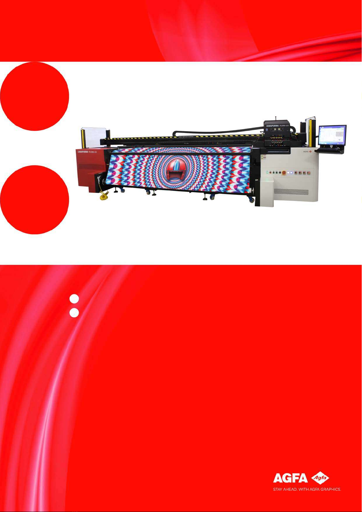
:Anapurna H3200i LED Advanced Operator Manual (v1.0)
Automatic Tension Compensation ........................................................................ 61
Using the Tension Compensation..................................................................... 62
Tips and tricks ...................................................................................................... 64
Chapter 7 Image quality procedures ............................................................................................. 67
Setting the Head Gap............................................................................................... 67
Head Gap Procedures.......................................................................................... 67
Automatic Head Gap setting ............................................................................. 67
Setting Media Thickness Manually .................................................................. 68
Checking and clearing inkjet nozzles................................................................... 69
Prime (nozzle) check print................................................................................. 69
Dripping the Heads.............................................................................................. 71
Purging the print heads with ink...................................................................... 72
Checking and draining color heads ....................................................................... 73
Checking an Ink Circuit for Air.......................................................................... 73
Draining a color head.......................................................................................... 74
Image Quality levels ................................................................................................ 76
High Definition Quality....................................................................................... 76
High Quality.......................................................................................................... 76
Standard Quality .................................................................................................. 76
Production Quality............................................................................................... 76
Express Quality..................................................................................................... 76
Draft ....................................................................................................................... 76
Calibration.................................................................................................................. 77
Ink dot placement ............................................................................................... 77
Calibration............................................................................................................. 77
Calibration zone................................................................................................... 78
Horizontal Calibration......................................................................................... 78
Bidirectional Calibration .................................................................................... 81
Feed calibration ................................................................................................... 84
White ink circuit ....................................................................................................... 87
Automatic filling of the white ink circuit with storage flush or ink.......... 87
Improved auditive alarm indication................................................................. 88
Improved visual alarm indication..................................................................... 89
Alarm warning...................................................................................................... 90
Activate the alarm reading ................................................................................ 90
Alarm indications and meaning........................................................................ 91
Purge time limitation.......................................................................................... 92
Vacuum switch off signal................................................................................... 92
Chapter 8 Printing............................................................................................................................. 93
Configurations overview.......................................................................................... 94
Chapter 9 Curing procedure ............................................................................................................ 95
Set UV light intensity............................................................................................... 95
UV Controls in the Printing Panel ......................................................................... 96
LED Combinations of the UV Modes................................................................ 96
Chapter 10 Maintenance procedure .............................................................................................. 101
Maintenance Schedule .......................................................................................... 101
Daily Maintenance ............................................................................................101
Weekly Maintenance........................................................................................101
Monthly Maintenance.......................................................................................101