manuals.online logo
Brands
  1. Home
  2. •
  3. Brands
  4. •
  5. AJAX
  6. •
  7. Security Sensor
  8. •
  9. AJAX DoorProtect User manual

AJAX DoorProtect User manual

1. FEATURES
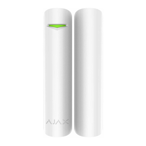
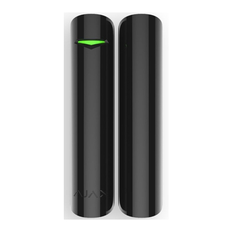
Wireless sensor Ajax DoorProtect is designated for doors and windows opening detection.
It functions as a part of Ajax security system.
SPECIFICATION MEANING
Sensor type wireless
Assembling type removable
Operating level 1 cm (0.4 in) (small magnet), 2 cm (0.8 in)
(big magnet)
Uses indoors
Socket to plug in the wire sensors available
Tamper protection button available
Radio signal power 20 mW
Radio-frequency range 868 MHz (Europe); 915 MHz (USA)
Maximum distance between sensor
and central unit 2000 m (6562 ft) (open area)
Power supply CR123A battery
Power supply voltage 3V
Battery life Up to 7 years
Operation temperatures range from 0°С (+32°F) to +50°С(+122°F)
Operation humidity up to 80%
Dimensions Ø20х90 mm (0.78x3.54 in)
3. COMPONENTS
4. SETTING-UP PROCEDURES
4.1 Before installing the sensor, it is required to register it with the Ajax security system. In
order to register the sensor, it is necessary to switch the Ajax security system’s receiver to
«Add Device» mode (the receiver’s manual explains how to accomplish it) and to put the
switch «2» (PICTURE 3) on the sensor to the «ON» position. Sensor’s light must blink at the
moment of switching on. The registration request is transmitted at the moment the sensor
is switched on only! In case the registration was not successful, switch off the sensor, wait for
5 seconds and switch it on again. If the sensor’s light blinks constantly (each second during
one minute), it means that the sensor is not registered. The light blinks in the same way if the
sensor is deleted from the registration list. Non-registered sensor blinks also throughout 3
seconds during each activation.
4.2 Having registered the sensor successfully, select an appropriate location to install it.
2. SPECIFICATIONS
ATTENTION!
Make sure that in the installation location sensor has a stable radio contact with
the receiver! A maximum distance of 2000 m (6562 ft) between the sensor and the
central unit is mentioned as a comparison with other devices. This distance was found
as a result of open area tests. Connection quality and distance between the sensor
and the receiver can vary depending on installation location, walls, compartments,
bridgings, as well as the thickness and constructional material. Signal coming through
obstacles, loses power. For example, distance range between the sensor and receiver,
divided with two reinforced concrete bearing walls, constitutes approximately 30 m
(98.4 ft). Please note that moving the sensor alongside the doors even 10 cm (4 in), it is
possible to improve the signal reception considerably.
DoorProtect
Make sure to check the signal strength! It is possible to launch a signal level test on the
receiver’s side. Test launching is described in the receiver’s manual.
ATTENTION!
Signal level test and detection zone test for sensors take some time to start. A certain
period of time is necessary for the receiver to send a test request to the sensor, and for
the sensor to send a test response.
RECEIVER SENSOR'S LIGHT EMITTING DIODE DESCRIPTION
3 indication bars lights almost permanently, with short
breaks each 1.5 seconds excellent signal
2 indication bars blinks 5 times per second medium signal
1 indication bar blinks twice per second low signal
0 bars short flashes each 1.5 seconds no signal
5. INSTALLATION
5.1 In order to assemble the sensor and the big magnet, lift up the plastic SmartBracket
panel with your finger (PICTURE 1), move it alongside the frame and remove it.
In order to assemble the small magnet, take its fastening clip out of the frame lifting it up
with a screwdriver (PICTURE 2).
DoorProtect opening detection sensor, magnet, external contact, battery CR123A,
installation set, manual
QR
QR
PICTURE 1. The sensor’s
and the big magnet’s
fastening clip
Move down
and
lift up
PICTURE 2.
Small magnet
assembling
5.2 Install the fastening clip SmartBracket on the door frame and door or window frame
and window with a help of the expansion bolts and self-tapping screws included in the set.
5.3 Put the sensor on the SmartBracket. Once the sensor is fixed on the SmartBracket, its
light must blink. It means that the tamper on the sensor is shut. In case the sensor does not
blink, the tamper status must be checked at the receiver configuration software!
ATTENTION!
Small magnet fits better for the installing when the door shut and the door jamb are
perpendicular. Big magnet fits better for the installing with the door shut and the
door jamb to be in a single plane. Be careful while installing the assembling clip.
Overexertion while installing can cause deformation and, as a result, impossibility to
install the sensor or to its unreliable fastening. The main body of the sensor is to be
installed on the fixed part of door frame or window frame, and the magnet is to be
installed on the moving part of the door or window. The magnet is to be located in
parallel with the sensor’s main body and opposite to the special sign (triangle) on it
(PICTURE 4). Fix the SmartBracket with the set’s assembling units only! Other fixing
system use, for example, self-tapping screws of big diameter, can damage fastening
clip. Together with self-tapping screws, there is a double stick tape in the set. It can be
used for temporary sensor fixing only. It is recommended not to use the tape for the
permanent fixing, as the tape is drying up over a time and the sensor may fall down
which can cause alarm actuation.
5.4 The opening detection sensor is installed!
5.5 In order to connect an additional wire sensor, plug in its wire to the socket “4” (PICTURE
3) on the sensor, and pass the wire through the sensor’s opening having removed the
cover “5” (PICTURE 3) from the sensor.
1 – Front cover trigger
2 – Cut-off switch
3 – Tamper button
4 – Socket for wire sensors
5 – Cover on the sensor for the wire
sensors’ wires
1
2
ON
OFF
5 5
4
3
PICTURE 3.
The sensor’s back cover
5.6 The longer the wire of the removable sensor is, the bigger are the risks of its accidental
damage and the lower is the coverage quality. The distance suggested between the
removable sensor and the wireless sensor Ajax is no more than 1 m.
PICTURE 4.
Triangle detecting the sealed contact
6. MAINTENANCE
6.1 Maintenance is done once every 6 months. The sensor’s board must be cleared of dust,
spider web, and other impurities.
6.2 Never rub the sensor with substances containing alcohol, acetone, petrol and other
active solvents.
6.3 Replace the batteries up to date. If the battery level is low, the sensor sends an
appropriate signal to the alarm system receiver unit. When the battery has run down, with
detection, including the tamper triggering, the sensor together with a usual indication turns
on its light and turns it off placidly. In order to replace the battery, lift up the trigger “1”
(PICTURE 3) and remove the sensor’s front cover. Replace the «battery» (PICTURE 5) with
a new one, type CR123A.
PICTURE 5. The sensor with the back cover removed.
battery –+
ATTENTION!
The sensor’s autonomous work duration depends on the sensor’s triggering frequency
and the battery quality. With door opening 10 times per day and the 60 seconds of
sampling time, the battery life is 7 years. With door opening 60 times per hour and 12
seconds of polling period, the battery life of the new battery is approximately 2 years.
7. WARRANTY
7.1 The sensor’s warranty period is 24 months. The warranty does not cover the battery!
8. VIDEO GUIDE
8.1 A detailed video guide for Ajax DoorProtect sensor assembling and assessing is available
online on our website.
AJAX Systems Inc., www.ajax.systems, [email protected]

Other manuals for DoorProtect

6

Other AJAX Security Sensor manuals

AJAX FireProtect 2 User manual

AJAX

AJAX FireProtect 2 User manual

AJAX FireProtect User manual

AJAX

AJAX FireProtect User manual

AJAX FireProtect User manual

AJAX

AJAX FireProtect User manual

AJAX DoorProtect Plus User manual

AJAX

AJAX DoorProtect Plus User manual

AJAX DoorProtect Plus User manual

AJAX

AJAX DoorProtect Plus User manual

AJAX FireProtect 2 (Heat) Jeweller User manual

AJAX

AJAX FireProtect 2 (Heat) Jeweller User manual

AJAX MotionProtect Jeweller User manual

AJAX

AJAX MotionProtect Jeweller User manual

AJAX GlassProtect User manual

AJAX

AJAX GlassProtect User manual

AJAX GlassProtect User manual

AJAX

AJAX GlassProtect User manual

AJAX MotionProtect User manual

AJAX

AJAX MotionProtect User manual

AJAX HomeSiren User manual

AJAX

AJAX HomeSiren User manual

AJAX FireProtect 2 Jeweller User manual

AJAX

AJAX FireProtect 2 Jeweller User manual

AJAX MotionProtect User manual

AJAX

AJAX MotionProtect User manual

AJAX FireProtect 2 Jeweller User manual

AJAX

AJAX FireProtect 2 Jeweller User manual

AJAX MotionProtect Fibra User manual

AJAX

AJAX MotionProtect Fibra User manual

AJAX FireProtect User manual

AJAX

AJAX FireProtect User manual

AJAX CombiProtect User manual

AJAX

AJAX CombiProtect User manual

AJAX MotionProtect User manual

AJAX

AJAX MotionProtect User manual

AJAX DoorProtect Plus Jeweller User manual

AJAX

AJAX DoorProtect Plus Jeweller User manual

AJAX DoorProtect User manual

AJAX

AJAX DoorProtect User manual

AJAX FireProtect 2 Jeweller User manual

AJAX

AJAX FireProtect 2 Jeweller User manual

AJAX MotionProtect User manual

AJAX

AJAX MotionProtect User manual

AJAX DualCurtain Outdoor User manual

AJAX

AJAX DualCurtain Outdoor User manual

AJAX MotionProtect User manual

AJAX

AJAX MotionProtect User manual

Popular Security Sensor manuals by other brands

Emerson Dixell GDS41M Installing and operating instructions

Emerson

Emerson Dixell GDS41M Installing and operating instructions

Maxell MSS-MO1 user manual

Maxell

Maxell MSS-MO1 user manual

Visonic MCM-140 brochure

Visonic

Visonic MCM-140 brochure

brennenstuhl BDI-S 30 3210 Directions for use

brennenstuhl

brennenstuhl BDI-S 30 3210 Directions for use

Airmar TRIDUCER P58 Owner's guide and installation instructions

Airmar

Airmar TRIDUCER P58 Owner's guide and installation instructions

Samsung S-1 URX-P01 user manual

Samsung

Samsung S-1 URX-P01 user manual

ETC Echoflex Elaho Dual Tech Wall-mount Vacancy... installation guide

ETC

ETC Echoflex Elaho Dual Tech Wall-mount Vacancy... installation guide

BUCKINGHAM MFG 355 T Instructions & warnings

BUCKINGHAM MFG

BUCKINGHAM MFG 355 T Instructions & warnings

Isotronic 60068 operating manual

Isotronic

Isotronic 60068 operating manual

B.E.G. LUXOMAT LC-Mini 120 Installation and operation instruction

B.E.G.

B.E.G. LUXOMAT LC-Mini 120 Installation and operation instruction

Guardian Velocity Harness instruction manual

Guardian

Guardian Velocity Harness instruction manual

Apollo XP95A Series installation instructions

Apollo

Apollo XP95A Series installation instructions

Agilent Technologies G1314B VWD user manual

Agilent Technologies

Agilent Technologies G1314B VWD user manual

Honeywell FS24X user guide

Honeywell

Honeywell FS24X user guide

QUARTA RADEX RD1212 user guide

QUARTA

QUARTA RADEX RD1212 user guide

Essence CareHome ES700PIR user guide

Essence

Essence CareHome ES700PIR user guide

Gas Clip Technologies Multi Gas Clip user manual

Gas Clip Technologies

Gas Clip Technologies Multi Gas Clip user manual

Lince Sigma 1946-BOBBY180-24-AM-V Installation, operation and maintenance manual

Lince

Lince Sigma 1946-BOBBY180-24-AM-V Installation, operation and maintenance manual

manuals.online logo
manuals.online logoBrands
  • About & Mission
  • Contact us
  • Privacy Policy
  • Terms and Conditions

Copyright 2025 Manuals.Online. All Rights Reserved.