manuals.online logo
Brands
  1. Home
  2. •
  3. Brands
  4. •
  5. Alarmtech
  6. •
  7. Security Sensor
  8. •
  9. Alarmtech CD 400 User manual

Alarmtech CD 400 User manual

CD 400 Instruction Manual 4-CD400-01
© 2018 Alarmtech www.alarmtech.se Rev. CD 400_1845en
Detectors
Shock detector
Instruction Manual CD 400
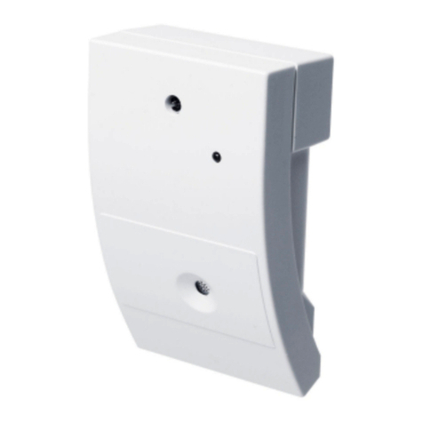
DESCRIPTION
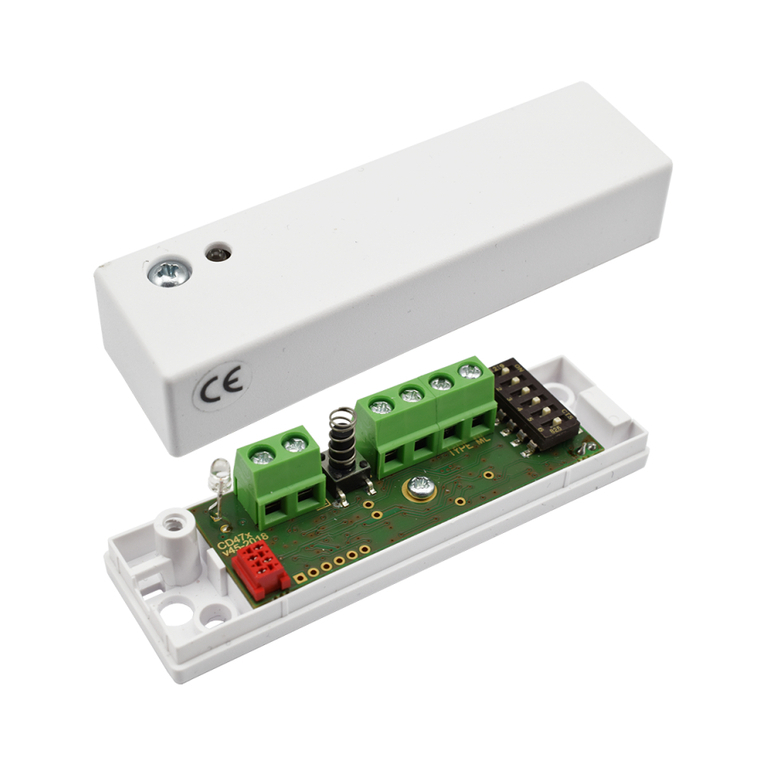
The CD 400 is a selectively sensing piezoelectric sensor that
detects and analyses the vibrations generated by the
attempts of an intruder to penetrate the protected area. The
highly sophisticated signal processing evaluates the
amplitude, frequency and duration of the vibrations
generated. The unit can be mounted on any stable surface
where an intrusion attempt might occur. However, the
following must be taken in to account:
1. The design and construction of the protected surface and
its material.
2. The detector location in relation to studs, joints,
door/windows hinges etc.
3. Background disturbances that can influence the detector.
COVERAGE
The typical coverage in various materials is shown in the
table below. The ranges are only presented as guidelines,
practical tests must always be conducted.
Material Steel/Wood/Glass Brick/Plaster Concrete
Range r = 3 m r = 2 m r =1 m
MOUNTING
1. Loosen the cover screws and remove it.
2. Select a suitable mounting position.
3. Use the bottom part as a template and mark the foxing
holes.
4. Use a 2-2.5 mm drill for the self-tapping screws provided.
Note! A clean and even surface under the detector will give
the beat coverage.
CONNECTION
The detector has 10 screw terminals with wire guard as
shown in Figure 1. The figure also shows the position of the
programming jumpers. A connection and programming
diagram is also filled inside the cover.
Note! Open inputs 3 & 4 are interpreted as low.
Figure 1. Connections to CD 400
PROGRAMMING JUMPERS
The four jumpers are used to programme the operational
modes of the detector. The functions are shown in Figure 2.
and also inside the cover.
S1 and S2 control the number of pulses to activate the alarm
relay.
S3 controls the alarm relay according to the following:
A) latched after activation, requiring a remote reset or
B) automatic reset after 2 seconds.
S4 controls the remote control and "DAY/NIGHT" functions.
On delivery all 4 jumpers are closed resulting in the
following:
S1, 2 - Reacts to a single impact (pulse).
S3 - The alarm relay is automatically reset after 2 seconds.
S4 - LED indicating an alarm activation.
Figure 2. Jumper functions
CD 400 Instruction Manual 4-CD400-01
© 2018 Alarmtech www.alarmtech.se Rev. CD 400_1845en
REMOTE DAY/NIGHT CONTROL
See Figures 3 and 4. Max 15 detectors.
NOTE! Jumper 4 must be open (removed)
Figure 4A shows DAY/NIGHT control with terminal 4, an
additional cable is required.
DAY = 0 V (open), LED indications active.
NIGHT = +12 V, no LED indications.
When changing from DAY to NIGHT, alarm memory is reset.
When the system is turned off, i.e. switched from NIGHT to
DAY, the LED lights up if the detector has been in alarm
mode. No other indications are displayed when activated
whether day or night time.
4B shows DAY/NIGHT control via terminal 4 with a second
control cable between detectors.
First / follow-up alarm storage is obtained by connecting the
terminals 3 to each other.
First alarm indicator - LED flashes
Follow-up alarm indicator - LED lights up
4C shows DAY/NIGHT control via terminal 4 with a second
Control cable together with first/follow-up alarm storage via
terminal 3 and TEST function.
First alarm indicator - LED flashes
Follow-up alarm indicator - LED lights up
Test with controller at terminal 3:
0 V (open) - no test and no indications
+12 V - TEST with LED indications.
Figure 3. Remote control functions
Figur 4. Remote controls
ADJUSTMENT AND SETTING-UP
Adjusting and setting is quite simple. Check that jumper 4 is
closed. The LED will then indicate an activation and the
alarm relay will reset two seconds after activation. If
programmed for multiple pulses each registered impact will
be shown by a short flash, the alarm will result in a longer
flash.
1. With jumper 4 closed turn the potentiometer clockwise to
the max. position.
2. Tap lightly close to the detector and check that each tap is
indicated and that the alarm relay is working properly after
the set number of pulses.
3. Turn the potentiometer anti-clockwise to the min.
position.
4. Use the test tool CT 400 at the most distant point to be
protected and gradually increase the sensitivity until the LED
indicates a received pulse.
5. Now make all connections permanent. Check that the
activation and tamper alarm are received at the control
panel.
TECHNICAL DATA
Supply voltage (norm 12V DC)
8-15 V DC
Max ripple
2 Vpp (at 12 V)
Current consumption (quiescent)
7mA
Current consumption (alarm)
11 mA
Alarm output
Relay, NC, 33 ohm
in series
Max. load
25V / 100mA
Alarm duration
2 seconds
Low voltage level projection
<8V
Alarm i
ndication
LED
Tamper (opening) protection
Micro switch, max.
25V / 100mA
Control voltage
for TEST LOW<3V, HIGH>6V
for Day/Night LOW<3V, HIGH>6V
Sensitivity adjustment
Potentiometer
Environmental conditions
Temperature (storage/functional) -20 - +50°C
Humidity max. 95% RH
Housing IP40 IEC
Interference prot
ection
-
RFI
15V/m, 0,1
-
1 GHz
Dimensions (LxWxH) 91 x 31 x 23 mm
Weight 40 g.
Approval VdS G197537

Other Alarmtech Security Sensor manuals

Alarmtech CD 470-I User manual

Alarmtech

Alarmtech CD 470-I User manual

Alarmtech MC 740-E User manual

Alarmtech

Alarmtech MC 740-E User manual

Alarmtech AD 800 Manual

Alarmtech

Alarmtech AD 800 Manual

Alarmtech AD 700 User manual

Alarmtech

Alarmtech AD 700 User manual

Alarmtech CD 470 User manual

Alarmtech

Alarmtech CD 470 User manual

Alarmtech MC 472 User manual

Alarmtech

Alarmtech MC 472 User manual

Alarmtech GD 370 User guide

Alarmtech

Alarmtech GD 370 User guide

Alarmtech MC 740-E User manual

Alarmtech

Alarmtech MC 740-E User manual

Alarmtech GD 335 User manual

Alarmtech

Alarmtech GD 335 User manual

Alarmtech MC 140 User manual

Alarmtech

Alarmtech MC 140 User manual

Alarmtech GD 375 Instruction Manual

Alarmtech

Alarmtech GD 375 Instruction Manual

Alarmtech MC 346 User manual

Alarmtech

Alarmtech MC 346 User manual

Alarmtech CD 470 User manual

Alarmtech

Alarmtech CD 470 User manual

Alarmtech AD 800-AM Manual

Alarmtech

Alarmtech AD 800-AM Manual

Alarmtech MC 340 2x4,7k User manual

Alarmtech

Alarmtech MC 340 2x4,7k User manual

Alarmtech MC 746-E User manual

Alarmtech

Alarmtech MC 746-E User manual

Alarmtech MC 740-E-M14 User manual

Alarmtech

Alarmtech MC 740-E-M14 User manual

Alarmtech MC 470 User manual

Alarmtech

Alarmtech MC 470 User manual

Popular Security Sensor manuals by other brands

YATO YT-73138 Original instruction

YATO

YATO YT-73138 Original instruction

Honeywell C7076A operating instructions

Honeywell

Honeywell C7076A operating instructions

AJAX MotionProtect quick start guide

AJAX

AJAX MotionProtect quick start guide

Toshiba TCB-LD1UPE Installation & operation manual

Toshiba

Toshiba TCB-LD1UPE Installation & operation manual

Powerfix Profi PMDL 5 A1 operating instructions

Powerfix Profi

Powerfix Profi PMDL 5 A1 operating instructions

Assa Abloy Yale SR-PIR Installation

Assa Abloy

Assa Abloy Yale SR-PIR Installation

Pyronix KX15DC-WE manual

Pyronix

Pyronix KX15DC-WE manual

CRESTO 1121 user guide

CRESTO

CRESTO 1121 user guide

Agilent Technologies 1260 Infinity user manual

Agilent Technologies

Agilent Technologies 1260 Infinity user manual

Larson Electronics MS-AT-7A-HV-WP instruction manual

Larson Electronics

Larson Electronics MS-AT-7A-HV-WP instruction manual

Better Water PB2 instructions

Better Water

Better Water PB2 instructions

Bluetech LD Series operating instructions

Bluetech

Bluetech LD Series operating instructions

Herz clever&smart narrow It Room Sensor installation manual

Herz

Herz clever&smart narrow It Room Sensor installation manual

3M DBI-SALA Nano-Lok XL Series instruction manual

3M

3M DBI-SALA Nano-Lok XL Series instruction manual

Bornack Stripe Comfort Click user manual

Bornack

Bornack Stripe Comfort Click user manual

NA-DE 10431 quick start guide

NA-DE

NA-DE 10431 quick start guide

YOSensi YO Pure Pro user guide

YOSensi

YOSensi YO Pure Pro user guide

Powerfix Profi 288019 Operation and safety notes

Powerfix Profi

Powerfix Profi 288019 Operation and safety notes

manuals.online logo
manuals.online logoBrands
  • About & Mission
  • Contact us
  • Privacy Policy
  • Terms and Conditions

Copyright 2025 Manuals.Online. All Rights Reserved.