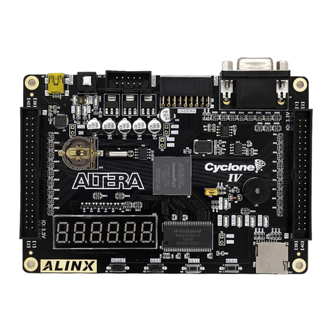
Alinx Cyclone IV FPGA User manual

Cyclone IV FPGA
Development Board
AX515
User Manual

2 / 52
Cyclone IV FPGA Development Board AX515 User Manual
Version Record
Version
Date
Release By
Description
Rev 1.0
2019-04-30
Rachel Zhou
First Release

3 / 52
Cyclone IV FPGA Development Board AX515 User Manual
Table of Contents
Part 1: FPGA Development Board Introduction.......................................... 5
Part 2: Structure Diagram........................................................................... 8
Part 3: Power.............................................................................................. 9
Part 4: FPGA Chip.....................................................................................11
Part 4.1: FPGA resources ..............................................12
Part 4.2: JTAG Interface.................................................12
Part 4.3: FPGA Power Supply........................................13
Part 5: 50Mhz Clock ................................................................................. 14
Part 6: SPI Flash Configuration chip ........................................................ 15
Part 7: QSPI Flash.................................................................................... 17
Part 8: DDR2 DRAM................................................................................. 19
Part 9: EEPROM 24LC04......................................................................... 23
Part 10:Real-Time Clock........................................................................... 24
Part 11: Gigabit Ethernet Interface ........................................................... 26
Part 12: USB to Serial Port....................................................................... 29
Part 13: VGA Port..................................................................................... 31
Part 14: USB 2.0 interface........................................................................ 33
Part 15: Audio Interface............................................................................ 36
Part 16: SD Card Slot............................................................................... 37
Part 17: Expansion Header ...................................................................... 39
Part 17.1: Expansion header J1.....................................40
Part 17.2: Expansion header J2.....................................42
Part 17.3: Expansion header J3.....................................46
Part 18: LED............................................................................................. 47
Part 19: Buttons........................................................................................ 48
4 / 52
Cyclone IV FPGA Development Board AX515 User Manual
Part 20: 7-segment displays..................................................................... 50

5 / 52
Cyclone IV FPGA Development Board AX515 User Manual
The FPGA development board (AX515) is an entry-level product, mainly for
FPGA beginners. The FPGA development board uses the ALTERA CYCLONE
IV family chips, model EP4CE15F23C8, in a 484-pin FBGA package. The
AX515 FPGA development board has a wealth of hardware resources and
peripheral interfaces. In the design, adhere to the "exquisite, practical, simple"
design concept, it is very suitable for software radio, industrial control,
multimedia applications, IC verification, parallel computing and other project
development, and it can also be applied to college teaching, FPGA training,
personal research learning and DIY etc.
Part 1: FPGA Development Board Introduction
This development board uses ALTERA CYCLONE IV series FPGA, model
EP4CE15F23C8, 484-pin FBGA package. The resources of this FPGA are
shown below:

6 / 52
Cyclone IV FPGA Development Board AX515 User Manual
Table 1-1: The Feature Summary of FPGA Device
The main resources and features are listed (see Table 1-2):
Parameter
Value
Logic elements (LEs)
15408
Embedded memory (Kbits)
504
Embedded 18 x18 multipliers
56
General-purpose PLLs
4
Global Clock Networks
20
User I/O Banks
8
Maximum User I/O
343
Table 1-1: The Main Resources and Feature of ALTERA EP4CE15F23C8
The layout of the board that indicates the location of the connector and key
components, provide a quickly overview of AX515 board (see Figure 1-2)

7 / 52
Cyclone IV FPGA Development Board AX515 User Manual
FPGA
EP4CE15F23C8
1Gbit
DDR2
50M
晶振
EEPROM
24LC04
实时时钟
128Mbit
FLASH
千兆以太
网芯片
USB2.0
芯片
USB转
串口
按键1
按键2
按键3
按键4
40针扩展口
6位数码管
复位键
千兆
网口
65535色
VGA接口 音频接口
40针扩展口
USB接
口
+5V
电源
接口
电源
开关
JTAG口
40针扩展口
3.3V电源
1.2V电源
1.8V电源
DDR电源
4个用户LED灯
电源
指示灯
64Mbit
配置芯片 音频芯片
Figure 1-2: The Layout of the AX 515
Through this diagram, we can see the functions that the development
platform can achieve.
+5V power input, maximum 2A current protection
A large-capacity 1Gbit high-speed DDR2 SDRAM can be used as a data
cache or as a memory for NIOS II operation;
A 64Mbit configuration chip EPCS64 (actually soldered to M25P64,
select EPCS64 when building project selection), can be used as
storage for FPGA configuration files
A 128Mbit QSPI FLASH that can be used as a storage for FPGA user
data
One-way 10/100M/1000M Ethernet RJ-45 interface for Ethernet data
exchange with computers or other network devices;
One-way high-speed USB2.0 interface, can be used for USB2.0
high-speed communication between FPGA development board and PC;

8 / 52
Cyclone IV FPGA Development Board AX515 User Manual
One USB Uart interface for serial communication with PC or external
devices
One-port VGA interface, VGA interface is 16bit, can display 65,536
colors, can display color pictures, etc
A high-quality audio interface that enables audio capture and output
functions;
A piece of RTC real time clock with battery holder, battery model CR1220
One piece of IIC interface EEPROM 24LC04
4 red user LEDs
4 independent user buttons
On-board 50M active crystal oscillator provides stable clock source for
FPGA development board
3-Way 40-pin ALINX expansion port (0.1 inch), each expansion port with
34 IO ports, one 5V power supply, two 3.3V power supplies, three GND.
Two expansion modules can be connected at the same time, such as
expansion modules such as 4.3-inch TFT module and AD/DA module.
Reserved JTAG port for FPGA debugging and program curing
One way Micro SD card slot, Support SD mode and SPI mode
Reserve a 2.5V power supply, which is Optional FPGA IO voltage 3.3V
and 2.5V
Part 2: Structure Diagram
The size of the development board is a compact 130mm x 90mm, and the
PCB is designed with a 6-layer board. There are 4 screw positioning holes
around the FPGA board for fixing the development board. The hole diameter of
the positioning hole are 3.3mm (diameter)

9 / 52
Cyclone IV FPGA Development Board AX515 User Manual
Figure 2-1: Structure Diagram
Part 3: Power
The power supply voltage of the AX515 FPGA development board is DC5V,
and Figure 3-1 is the power supply schematic:
5V 电源
输入
保险丝
MP1482
MP1482
TPS51200
3.3V/2A
1.2V/2A
VTT
VREF
MP1482
电源开关
1.8V/2A
CN1
F1
SW1
U6
U4
U5
U9
LT1117 2.5V/0.8A
LT1117 VCCIO(预留)
FPGA/GPHY
/FLASH/USB
FPGA Core
FPGA/DDR2
DDR2
FPGA analog
FPGA Bank7
IO
Figure 3-1: Block Diagram of Power Design

10 / 52
Cyclone IV FPGA Development Board AX515 User Manual
The FPGA development board is powered by +5V, and is converted into
+3.3V, +1.2V, +1.8V three-way power supply through three-way DC/DC power
supply chip MP1482, and generates +2.5V power supply and VCCIO (2.5V)
through two LDO LT1117. The 1.8V generates the VTT and VREF voltages
required by DDR2 through TPS51200 of TI. The functions of each power
distribution are shown in the following table:
Power Supply
Function
+3.3V
FPGA, Gigabit Ethernet, Serial Port, RTC, Flash, EEPROM,
USB 2.0, SD Card
+1.2V
FPGA Core
+1.8
DDR2, FPGA Bank3 Bank4
+2.5V
FPGAAnalog Power
VREF, VTT
0.9V, DDR2 reference voltage and termination voltage
VCCIO
2.5V, FPGA Bank7 optional
The IO voltage of FPGA BANK7 can be selected by two 0 ohm resistors
(R158, R159) on the FPGA development board. When R158 is installed and
R159 is not installed, the IO level of Bank7 is 3.3V. When R158 is not installed,
R159 is installed. At the time, the IO level of Bank 7 is 2.5V.
FPGA BANK voltage distribution:
BANK
Function
Voltage
Description
BANK1
1000M Ethernet
3.3V
BANK2
Expansion header J1
3.3V
BANK3
DDR2
1.8V
BANK4
DDR2
1.8V
BANK5
Digital tube, Expansion header J3
3.3V
BANK6
USB、SD card slot
3.3V
BANK7
LED,Expansion header J2
3.3V/2.5V
IO voltage is
adjustable
BANK8
Audio、EEPROM、VGA、RTC、UART
3.3V

11 / 52
Cyclone IV FPGA Development Board AX515 User Manual
In the PCB design, the 6-layer PCB is used, and a separate power supply
layer and GND layer are reserved, so that the power supply of the entire
development board has very good stability. Test points for each power supply
are reserved on the PCB so that the user can confirm the voltage on the board.
Part 4: FPGA Chip
As mentioned earlier, the FPGA model we use is EP4CE15F23C8, which
belongs to ALTERA CYCLONE IV. This model is a FBGA package with 484 pins.
Again, explain the definition of the FPGA pin. Many people use FPGAs that are
not BGA-packaged, such as 144-pin, 208-pin FPGA chips. Their pin definitions
are made up of numbers, such as 1 to 144, 1 to 208, etc., and when we use
BGA packages. After the chip, the pin name becomes in the form of letters +
numbers, such as E3, G3, etc., so when we look at the schematic, we see the
letters + numbers, which represent the pins of the FPGA. Having said this, let's
look at the functions of the various parts of the FPGA.
Figure 4-1: FPGA Chipset

12 / 52
Cyclone IV FPGA Development Board AX515 User Manual
Part 4.1: FPGA Resources
The EP4CE15F23C8 chip contains logic resources, built-in RAM, multiplier,
phase-locked loop, global clock network and IO port. The resources between
different types of FPGAs will be different. The resources of the FPGA model on
the AX515 development board are shown in Figure 3-2 below
Figure 4-2:FPGA internal resources
Part 4.2: JTAG Interface
First let's talk about the FPGA configuration and debugging interface: JTAG
interface. The function of the JTAG interface is to download the compiled
program (.sof) to the FPGA or download the configuration file (.jic) to the
configuration chip EPCS64. After the sof file is downloaded to the FPGA, it will
be lost after power-off. Re-download it. However, the JIC file that is solidified
into the configuration chip will not be lost after power-off. After power-on, the
FPGA will read the configuration file in the configuration chip EPCS64 and run it.
Figure 3-3 is the schematic part of the JTAG port, which involves the four

13 / 52
Cyclone IV FPGA Development Board AX515 User Manual
signals TCK, TDO, TMS, TDI.
Figure 4-3:JTAGE Schematic
The JTAG interface uses a 10-pin 2.54mm standard connector, and Figure
3-4 shows the JTAG interface on the FPGA development board.
Figure 4-4: JTAG Connector on the FPGA board
Part 4.3: FPGA Power Supply
Next, let's talk about the power supply pin part of the FPGA, where VCCIO
is the power supply pin of the Bank, which determines the level of the IO port
corresponding to each BANK. As shown in Figure 3-5, Bank1, Bank2, Bank5,
Bank6, Bank8 is connected to VCC3V3. The corresponding IO level of these
banks is 3.3V. Bank3 and Bank4 are connected to DDR2. The required IO is
1.8V, so we are connected to VCC1V8. Bank7 we set it to VCCIO7, where we

14 / 52
Cyclone IV FPGA Development Board AX515 User Manual
can choose the voltage according to our own needs, the default is 3.3V. Change
the resistance of R158 to R159 and change the BANK7 voltage to 2.5V. If there
are other requirements, different voltages can be achieved by replacing the
power supply chip U19.
Figure 4-5: FPGA Power Supply
Part 5: 50Mhz Clock
Figure 5-1 is the 50M active crystal oscillator circuit mentioned above that
provides the clock source for the FPGA development board. The crystal output
is connected to the global clock (GCLK Pin T21) of the FPGA, which can be
used to drive the user logic within the FPGA. The user can configure the internal
PLLs of FPGA to achieve a higher clock.

15 / 52
Cyclone IV FPGA Development Board AX515 User Manual
Figure 5-1: 50Mhz Crystal Oscillator
Figure 5-2: 50Mhz crystal oscillator on the FPGA Development Board
Clock Pin Assignment
Net Name
FPGA PIN
CLK
T21
Part 6: SPI Flash Configuration chip
A 64Mbit configuration chip is used on the development board, the model is
M25P64. This chip is fully compatible with the configuration chip EPCS64.
When we make the configuration chip selection, we can directly select EPCS64.

16 / 52
Cyclone IV FPGA Development Board AX515 User Manual
Due to its non-volatile nature, the configuration chip can be used as a storage
device for storing configuration information of the FPGA system during use, and
can also save information content when power is off. When power is restored,
the configuration chip EPCS64 transfers the configuration information to the
FPGA and then runs.
The specific models and related parameters of SPI FLASH are shown in
Table 6-1
Part
Device
Size
Manufacturer
U7
M25P16VMF
64M bit
ST
Table 6-1: The model of SPI Flash and Parameters
Figure 6-1: The Hardware Design of SPI FLASH

17 / 52
Cyclone IV FPGA Development Board AX515 User Manual
Figure 6-2: EPCS64(M25P64) on the FPGA board
Configure chip pin assignments:
Pin Name
FPGA Pin
ASDO
D1
DCLK
K2
nCSO
E2
DATA0
K1
Part 7: QSPI Flash
The AX515 FPGA development board is equipped with a 128MBit
Quad-SPI FLASH chip, model W25Q128, which uses the 3.3V CMOS voltage
standard. Due to the non-volatile nature of QSPI FLASH, In use, QSPI FLASH
can be used as power-down storage for user data. It mainly includes user data,
image information and system files, and so on. The specific models and related

18 / 52
Cyclone IV FPGA Development Board AX515 User Manual
parameters of QSPI FLASH are shown in Table 7-1.
Position
Model
Capacity
Factory
U17
W25Q128BV
128M Bit
Winbond
Table 7-1: QSPI FLASH Specification
Figure 7-1: QSPI Flash Schematic

19 / 52
Cyclone IV FPGA Development Board AX515 User Manual
Figure 7-2: QSPI Flash chip on the FPGA board
Configure chip pin assignments:
Pin Name
FPGA Pin
QSPI_CLK
A7
QSPI_CS
A6
QSPI_MISO0
B7
QSPI_MISO1
B6
QSPI_MISO2
E9
QSPI_MISO3
B8
Part 8: DDR2 DRAM
The development board contains a high-speed DDR2 DRAM, model:
MT47H64M16HR-3IT, capacity: 1Gbit (64M*16bit), 16bit bus. The FPGA and
DDR2 DRAM on the development board are connected to the IO of BANK3 and
BANK4, and the level is 1.8V. The clock frequency between the FPGA and

20 / 52
Cyclone IV FPGA Development Board AX515 User Manual
DDR2 is up to 166.7MHz, and the data frequency is up to 333MHz. The
hardware design of DDR2 requires strict consideration of signal integrity. In the
circuit design and PCB design, the matching resistor/terminal resistor, trace
impedance control, and trace length control have been fully considered to
ensure the high-speed stability of DDR2.
Figure 8-1: DDR2 DRAM Schematic
This manual suits for next models
1
Table of contents
Other Alinx Motherboard manuals

Alinx
Alinx AC7Z035B User manual

Alinx
Alinx KINTEX-7 FPGA User manual

Alinx
Alinx AX301 User manual

Alinx
Alinx ZYNQ UltraScale+ AXU2CG-E User manual

Alinx
Alinx AX7102 User manual

Alinx
Alinx AXU4EV-E User manual

Alinx
Alinx ZYNQ7000 FPGA User manual

Alinx
Alinx AC7Z100 User manual

Alinx
Alinx AXU2CGA User manual

Alinx
Alinx ARTIX-7 FPGA User manual

Alinx
Alinx ZYNQ UltraScale+ User manual

Alinx
Alinx AV4040 User manual

Alinx
Alinx ACU15EG User manual

Alinx
Alinx AXKU041 User manual

Alinx
Alinx ARTIX-7 FPGA User manual

Alinx
Alinx Zynq UltraScale+MPSoC User manual

Alinx
Alinx AX7A200 User manual

Alinx
Alinx ARTIX-7FPGA User manual

Alinx
Alinx AX7050 User manual

Alinx
Alinx AC7015 User manual