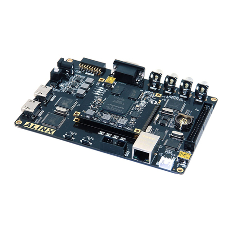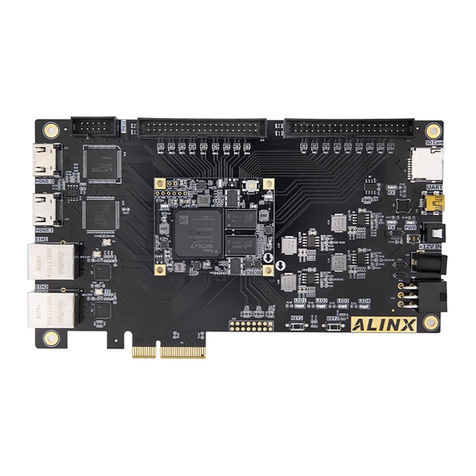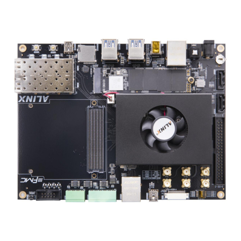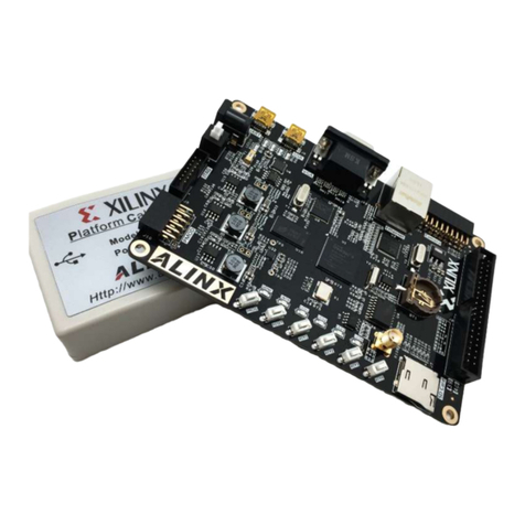
Spartan-7 FPGA Development Board AX7050 User Manual
Amazon Store: https://www.amazon.com/alinx
Table of Contents
Version Record.......................................................................................... 2
Part 1: FPGA Development Board Introduction......................................... 6
Part 2: AC7050 core board...................................................................... 10
Part 2.1: AC7050 Core Board Introduction........................................10
Part 2.2: FPGA Chip..........................................................................12
Part 2.3: Active Differential Crystal....................................................13
Part 2.4: DDR3 DRAM ......................................................................15
Part 2.5: QSPI Flash .........................................................................19
Part 2.6: LED Light on Core Board....................................................20
Part 2.7: JTAG Interface....................................................................21
Part 2.8: Power Interface on the Core Board ....................................22
Part 2.9: Board to Board Connectors pin assignment .......................23
Part 2.10: Power Supply....................................................................27
Part 2.12: Structure Diagram.............................................................30
Part 3: Carrier Board ............................................................................... 32
Part 3.1: Carrier Board Introduction ..................................................32
Part 3.2: Gigabit Ethernet Interface...................................................33
Part 3.3: HDMI Output Interface........................................................35
Part 3.4: USB2.0 Interface ................................................................37
Part 3.5: SD Card Slot.......................................................................39
Part 3.6: USB to Serial Port...............................................................40
Part 3.7: EEPROM 24LC04...............................................................42
Part 3.8 : Real time clock DS1302 ....................................................43
Part 3.9: Expansion Header ..............................................................44
Part 3.10: JTAG Interface..................................................................46
Part 3.11: Camera Module Interface .................................................47
Part 3.12: Buttons..............................................................................48
