IVA-D100/IVA-D100E
DC/DC Converter
•Do not install the converter at a location subjected to water
such as under the floor mat or air conditioner. This may cause a
malfunction.
•Do not bundle the DC/DC converter cable with other audio
cables. Also, do not install the cables directly next to the unit.
Doing so may induce noise into your system.
•Keep the DC/DC converter away from the Antenna cables and
the rear side of the unit, otherwise noise may be generated when
receiving radio broadcast.
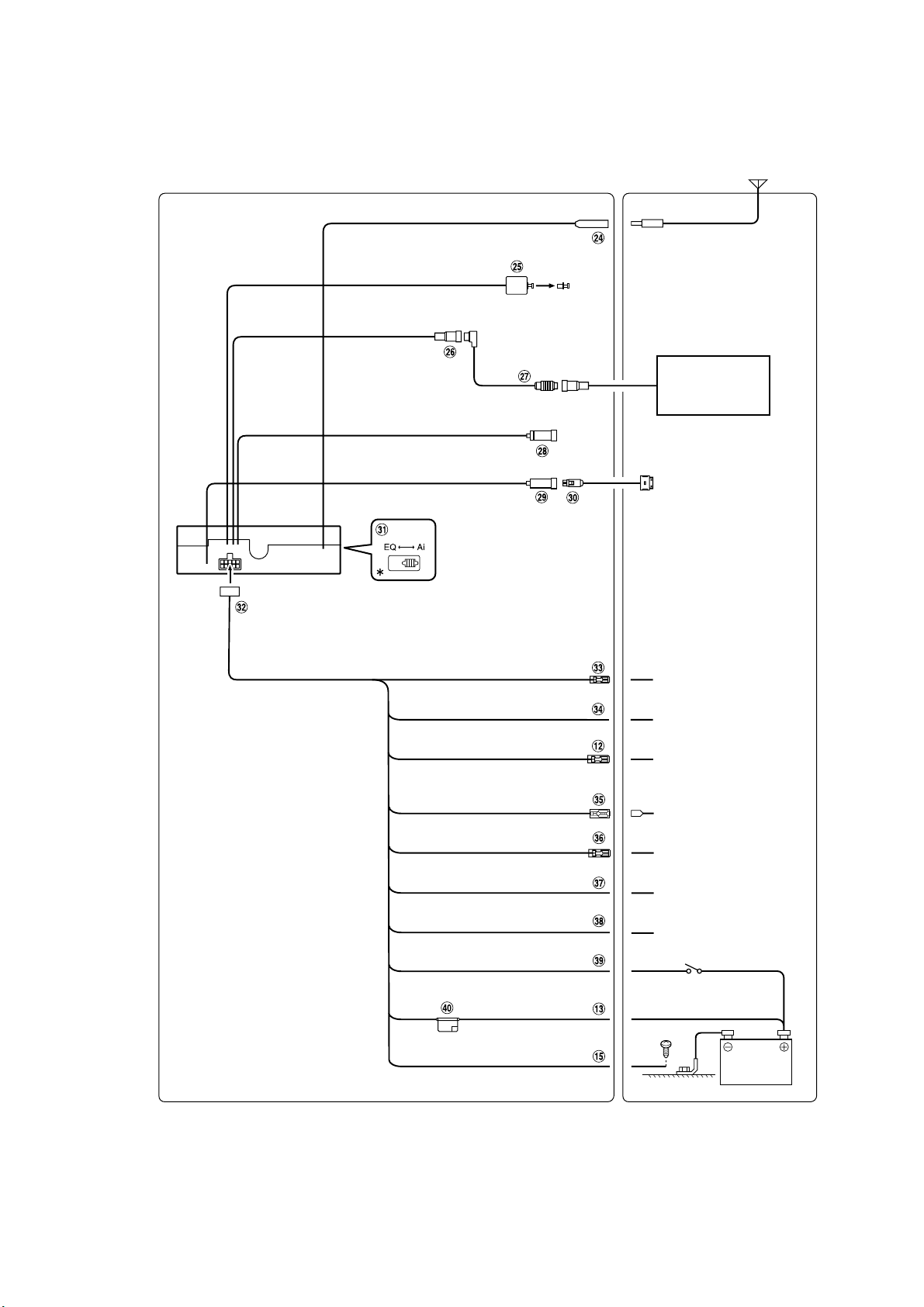
Video Input Connector (AUX INPUT) (Yellow)
Input the video.
Audio Input Connectors (AUX INPUT)
RED is right and WHITE is left input the audio.
Video Output Connector (Yellow)
Output the video.
Subwoofer RCA Connectors
Connect the input lead of an amplifier for the subwoofer to
this terminal.
Front Output RCA Connectors
RED is right and WHITE is left.
Rear Output RCA Connectors
RED is right and WHITE is left.
RCA Extension Cable (sold separately)
RCA Extension Cable (Included)
Rear Input Terminals
Front Input Terminals
Remote Turn-On Lead (Blue/White)
Connect this lead to the remote turn-on lead of your
amplifier or signal processor.
Battery Lead (Yellow)
Connect this lead to the positive (+) post of the vehicle’s
battery.
Fuse Holder (15A)
Ground Lead (Black)
Connect this lead to a good chassis ground on the vehicle.
Make sure the connection is made to bare metal and is
securely fastened using the sheet metal screw provided.
Right Front (+) Speaker Output Lead (Gray)
Right Front (–) Speaker Output Lead (Gray/Black)
Right Rear (–) Speaker Output Lead (Violet/Black)
Right Rear (+) Speaker Output Lead (Violet)
Left Rear (+) Speaker Output Lead (Green)
Left Rear (–) Speaker Output Lead (Green/Black)
Left Front (–) Speaker Output Lead (White/Black)
Left Front (+) Speaker Output Lead (White)
Antenna Receptacle
Digital Output Terminal (Optical)
Use when combining fiber digital input compatible
products.
Ai-NET Connector
Connect this to the output or input connector of another
device (CD Changer, Equalizer, HD Radio™ TUNER
MODULE, etc.) equipped with Ai-NET.
•Interface adapter (KCA-420i) is not recommended for use with this
product.
•You can input TV/video sound by connecting an optional Ai-NET/
RCA Interface cable (KCA-121B) to this component.
Ai-NET Cable (Included with CD Changer)
RGB Input Terminal
Connect this to the RGB output terminal of the Navigation
System.
iPod Direct Connector
Control iPod signals.
Connect this to an iPod, using the (sold separately) FULL
SPEED™ Connection Cable (KCE-422i).
FULL SPEED™ Connection Cable (KCE-422i) (sold
separately)
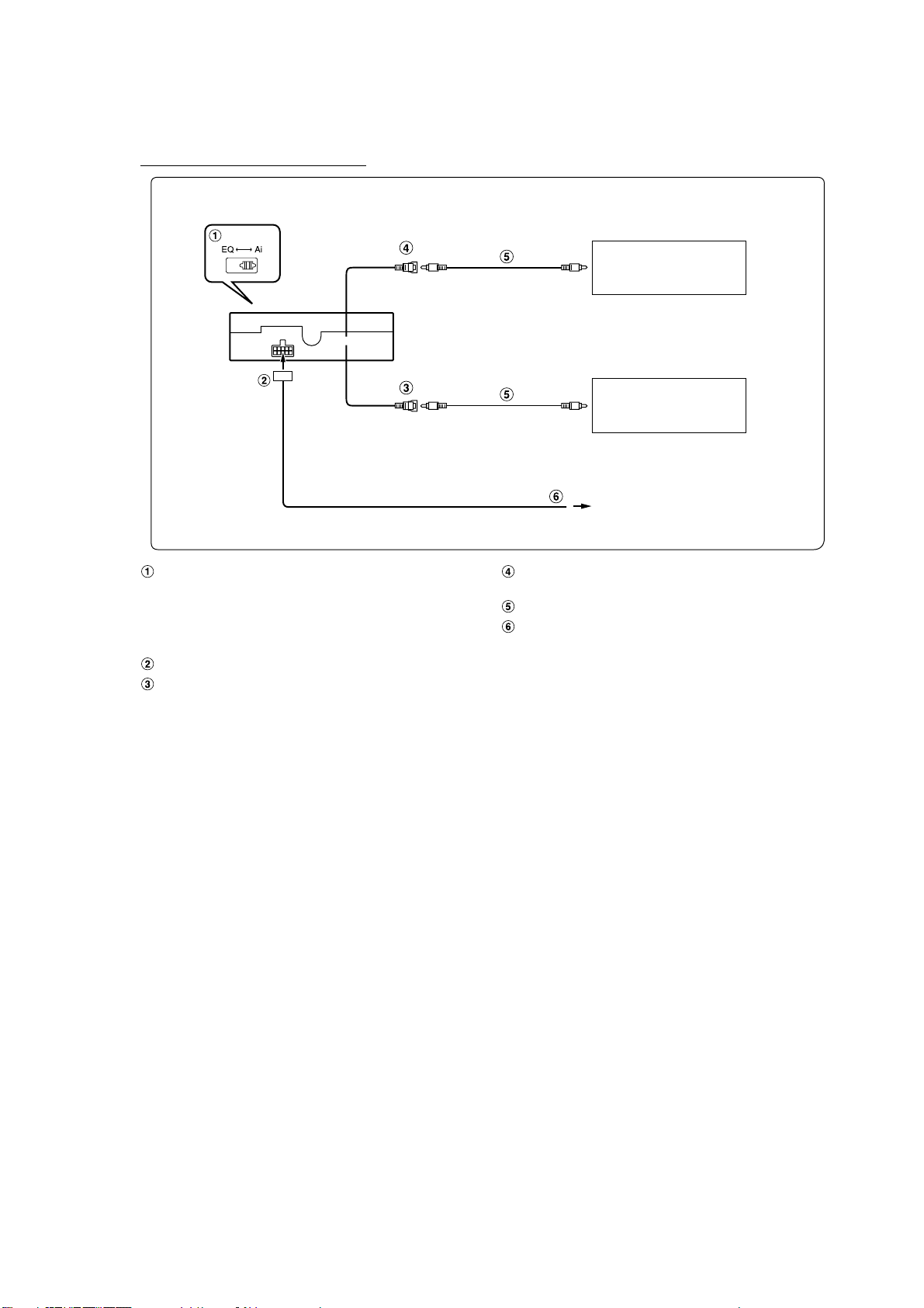
System Switch
When connecting a processor or divider using Ai-NET,
place this switch in the EQ position. When no device is
connected, leave the switch in the Ai position.
•Be sure to turn the power off to the unit before changing the switch
position.
Power Supply Connector
Remote Control Output Lead (White/Brown)
Connect this lead to the remote control input lead. This lead
outputs the controlling signals from the remote control.
Reverse Lead (Orange/White)
Use only when a back-up camera is connected. Connect to
the plus side of the car's reverse lamp that lights when the
transmission is shifted into reverse (R).
Switches the video picture to the back-up camera. This is
linked with putting the car into reverse (R).
Power Antenna Lead (Blue)
Connect this lead to the +B terminal of your power antenna,
if applicable.
Audio Interrupt In Lead (Pink/Black)
Parking Brake Lead (Yellow/Blue)
Connect this lead to the power supply side of the parking
brake switch to transmit the parking brake status signals to
the IVA-D100.
Foot Brake Lead (Yellow/Black)
Connect to the vehicle's foot brake lead or brake lamp lead.
Switched Power Lead (Ignition) (Red)
Connect this lead to an open terminal on the vehicle’s fuse
box or another unused power source which provides (+)
12V only when the ignition is turned on or in the accessory
position.
Fuse Holder (7.5A)