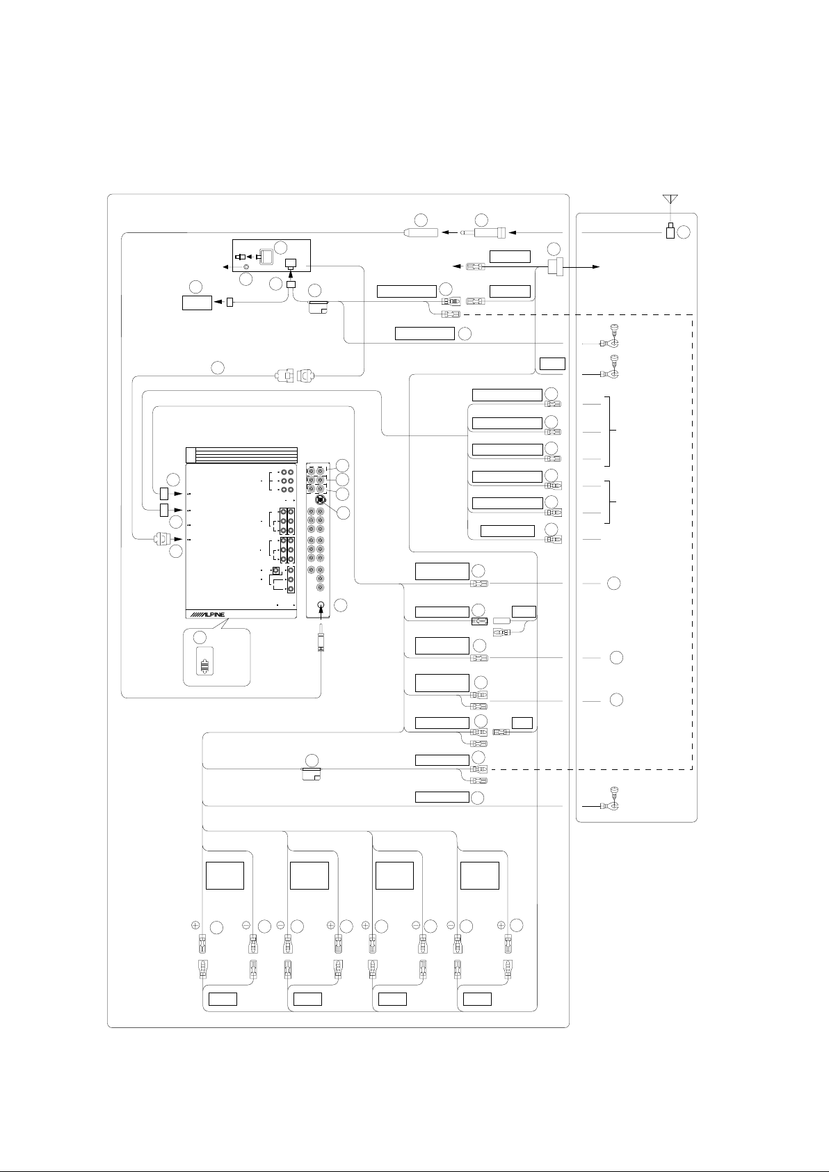
Alpine IVA-D900R User manual

IVA-D900R
SERVICE MANUAL
Mobile Multimedia Station
DIGITAL VIDEO
4/03-A
68E35542S01
Caution : The part marked with !is generating a high Voltage, so care will be
necessary when working.
* The model is component system unit of Monitor Unit, Tuner Unit and DC/DC Converter Unit.
* DVD region number (playable region number) : Region Number 2 or ALL
TO ALPINE Home Page

<Cautions for Safe Repair Work>
The following cautions will prevent accidents in the workplace and will ensure safe products.
*The symbols indicate caution is needed to prevent injuries and damage to property.
The symbols and their meanings follow.
*The following symbols indicate two levels of cautions.
When you see this symbol, you have to be very careful.
When you see this symbol, you have to follow the instructions there.
Do not look squarely into the laser light
Fuse Caution
coming from the pickup. Always use a designated fuse.
You may loose you sight. Use of an incorrect fuse may result in a fire.
Do not allow wiring to be caught in the Battery Caution
screw/chassis. Use the designated battery.
If wiring is caught in the screw/chassis, it may Confirm the correct polarity and seat of the battery.
cause a short circuit, resulting in a fire. An incorrect battery or an improperly connected or
seated battery may result in a fire.
High Temperature Caution Designated Parts Caution
Touching the heat sink may cause severe burns. Look up the part list and ensure that only
designated parts are used to prevent problems or
accidents.
Reverse Power Supply Connections o
r
Wiring Caution
Misconnections Caution Ensure that the wiring is correct when rewiring to
Reverse power supply connections or prevent problems with ignition/breakdown.
misconnections may cause ignition problems and
smoke may result.
Soldering Caution Wear Glove
s
Hot solder from solder splash may cause severe Wear gloves to prevent electrical shocks or injury
burns. from the end face of the metal.
For the FDA laser standard, the following CAUTION label is stuck on each product
.
Please be careful for repair.
If you ignore this symbol and handle the product incorrectly or unsafely,
injury or only material damage may result.
If you ignore this symbol and handle the product incorrectly or unsafely,
serious injury or death may result.
Warning
Caution
Warning
Caution
CAUTION-Laser radiation when open, DO NOT STARE INTO BEAM

Packing Assembly Parts List
Packing Method View
System Connections
Adjustment Procedures
Extension Cable
* Monitor Unit Block
* Tuner Unit Block
* DC/DC Converter Unit Block
NOTE : Due to continuing product improvement, specifications and designs are subject to
change without notice.
Contents
Cabinet Assembly Parts List (Monitor Unit)
DVD Deck Mechanism Assembly Parts List
Electrical Parts List (Monitor Unit)
Cabinet Assembly Parts List (Tuner Unit)
Electrical Parts List (Tuner Unit)
Cabinet Assembly Parts List
(DC/DC Converter Unit)
Electrical Parts List
(DC/DC Converter Unit)

402
401
405 416
417
403
DC/DC Converter Unit
to
405
408
412 411 413
415
409
407
416
Tuner Unit
Monitor Unit
404
X4
X1
X1
X4
X6
404
402
415 -1 415 -2
415 -3
X1
401
410
406
414
X1
X1
415 -6
415 -5
X1
415 -4
Symbol
No.
Part No.
Description
401
402
403
404
405
406
407
408
409
410
411
412
15D61379Y01
33C60496Y01
15B41543Y01
01T55446Y02
01T95334W02
01T95205W13
01T35047Y04
01T65556Y01
01T65563Y01
07T75070W01
07B50413W05
07B50413W06
CASE,INNER
FACE,PLATE
CARRING,BAG
ASSY,REMOCON RUE4191
ASSY,ANT WIRE MAIN
ASSY,WIRE PWR D900JR
ASSY,WIRE REMOTE 900
ASSY,POWER WIRE RAD
ASSY,DIN CABLE 3M
BKT,STOPPER ASSY
BKT,SIDE(L)
BKT,SIDE(R)
Symbol
No.
Part No.
Description
413
414
415-1
415-2
415-3
415-4
415-5
415-6
416
417
75T58346F16
01T15087Y01
03S60820Y15
03S60828Y03
03A31982Y01
36A11113W01
03A60836Y01
60T55630W01
01A31635Y02
68P50520Y88
PAD,MAGIC TAPE
ASSY,CVA-1000R ISO
SCR,MCH 4X8 ZN A
SCR,TPG 4X14 ZN A
SCR,M4X5 FLAT
CAP,RUBBER(A)
SCR,CUS 5X7 ZN A
BAT,MGN R03(NB)UM-4
ASSY,KIT REMOCON
O/M AOEU
Packing Assembly Parts List
Packing Method View
TO CONTENTS

SUB W.
REAR
FRONT
Ai-NET
L
R
VIDEO
CAMERA IN
(MONO)
L
AUX IN 3
R
RADIO ANTENNA IN
REMOTE IN/OUT
NAVIGATIONIN
DISPLAYOUT
POWER SUPPLY
VIDEO
AUDIO
(MONO)
L
AUX IN 1/2
R
AUDIO
VIDEO
L
AUX OUT
R
PREOUT
AUDIO
1
2
1
2
3
6
Antenna
To the instrument cluster
illumination lead
SPEAKER
LEFT
FRONT
(White) (White/
Black)
(Green/
Black)
(Green) (Violet) (Violet/
Black)
(Grey/Black) (Grey)
SPEAKER
LEFT
REAR
GND
R-Lch
5
(Yellow)
BATTERY
ACC
(Pink/Black)
(Yellow/Blue)
(Red)
ACC
(Red)
P.ANT
(Blue)
(Yellow)
(Black)
AUDIO
INTERRUPT IN
PARKING
BRAKE
REMOTE
TURN-ON
POWER ANT
BATTERY BATT
ILLM
SPEAKER
RIGHT
REAR
SPEAKER
RIGHT
FRONT
2
3
1
GND
(Black)
5
4
(Yellow)
(Orange)
(Blue)
(Blue/White)
F-Lch R-Rch F-Rch
*Note: Be sure to connect the leads
correctly after identifying the ISO
connector terminals for the Battery
and Ignition (ACC).
IVA-D900R
Tuner BOX
8
9
10
GND 6
7
REVERSE
REMOTE OUT AUX2
NORM
EQ/DIV
REMOTE OUT AUX1
REMOTE OUT AUX3
REMOTE IN AUX1
REMOTE IN AUX2
IVA-D900R
<Monitor>
(Black)
To remote
input lead.
*Set the system switch to "NORM" when only a changer is connected (when the Ai-NET
compatible equalizer is not used).
To remote
output lead.
To plus side of the
back lamp signal
lead of the car
(White/Brown)
(White/Brown)
(Orange/White)
(White/Brown)
(White/Brown)
(White/Brown)
Nothing connects
with this line.
To remote control
interface box
System Connections
11
21
24
26
*
17
17
17
18
18
19
20
22
23
25
27*
28
38
39
40
14
15
37
10
12
13
16
36 35 34 33 32 31 30 29
TO CONTENTS

1ISO Antenna Plug
2ISO Antenna Converter Plug (Included)
3Antenna Extension Cable
4ISO Connector (Included)
5Battery Lead (Yellow)
Connect this lead to the positive (+) post of the vehicle's
battery.
6Ground Lead (Black)
Connect this lead to a good chassis ground on the
vehicle. Make sure the connection is made to bare metal
and is securely fastened using the sheet metal screw
provided.
7Fuse Holder (10A)
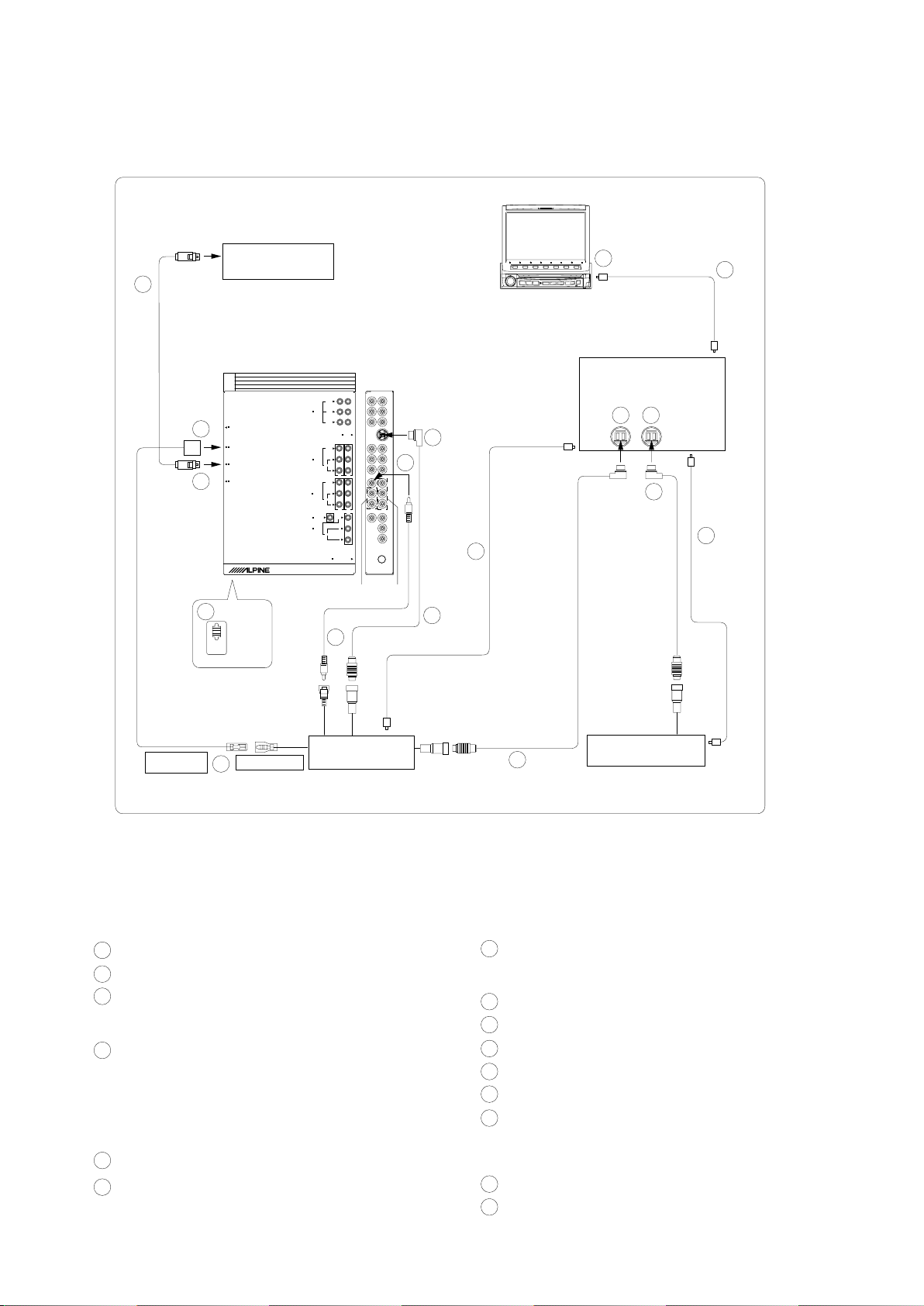
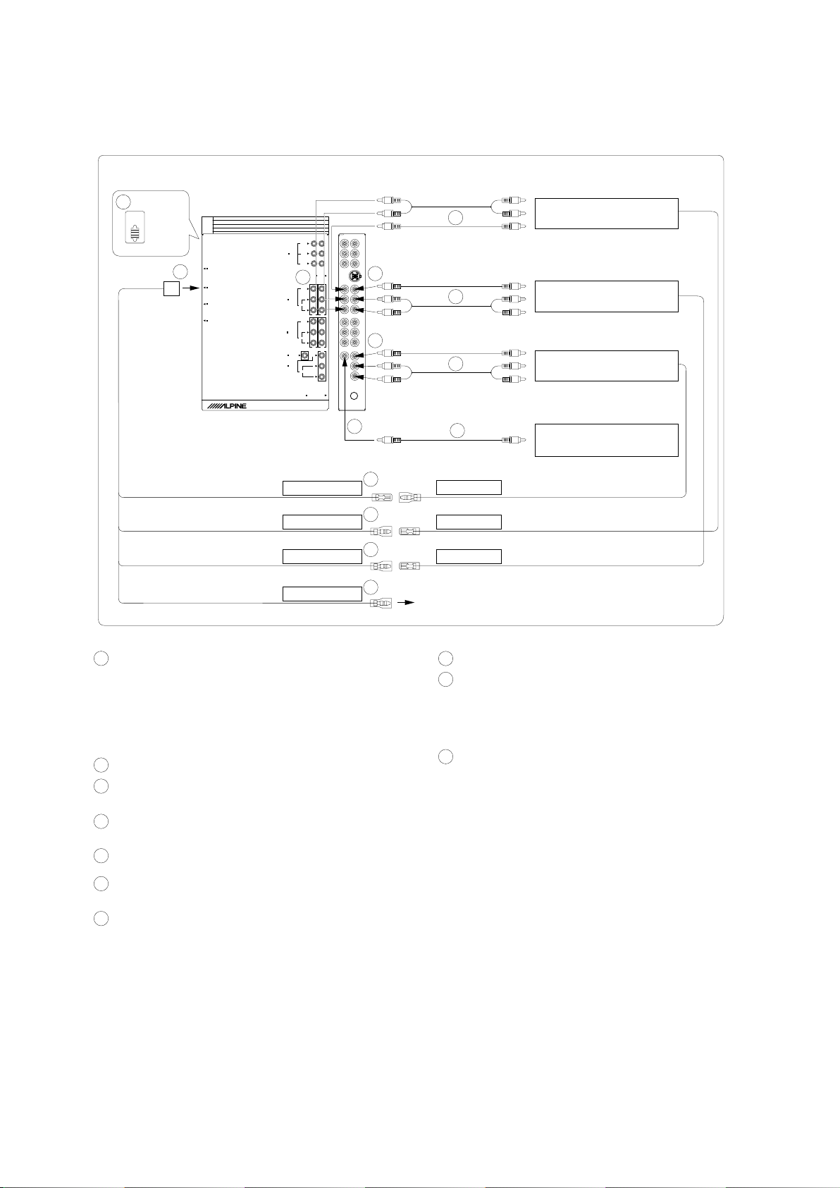
8Digital Output Terminal (Optical)
Use when combining fiber digital input compatible
products.
9Remote Control Interface Connector
Connect to the remote control interface box.
Power Supply Connector
DC/DC Converter
*Do not install the converter at a location subjected to water
such as under the floor mat or air conditioner. This may cause
a malfunction.
*Do not bundle the DC/DC converter cable with other audio
cables. Doing so may induce noise into your system.
*Keep the DC/DC converter away from the Antenna cables and
the rear side of the unit, otherwise noise may be generated
when receiving radio broadcast.
Remote IN/OUT Terminal
Display Output Terminal
Ai-NET Connector
Connect this to the output or input connector of other
product (CD changer, Equalizer, etc.) equipped with Ai-
NET.
Antenna Receptacle
System Switch
When connecting an equalizer or divider using Ai-NET
feature, place this switch in the EQ/DIV position. When no
device is connected, leave the switch in the NORM
position.
*Be sure to turn the power off to the unit before changing the
switch position.
Remote Control Output Lead (White/Brown)
Connect this lead to the remote control input lead. This
lead outputs the controlling signals from the remote
contro l.
Remote Control Input Lead (White/Brown)
Connect the external Alpine product to the remote contro l
output lead.
Reverse Lead (Orange/White)
Use only when a back-up camera is connected. Connect
to the plus side of the car's reverse lamp that lights when
the transmission is shifted into reverse (R).
Switches the video picture to the back-up camera. This is
linked with putting the car into reverse (R).
RemoteTurn-On Lead (Blue/White)
Connect this lead to the remote turn-on lead of your
amplifier or signal processor.
To amplifier or equalizer
Power Antenna Lead (Blue)
Connect this lead to the +B terminal of your power
antenna, if applicable.
Audio Interrupt In Lead (Pink/Black)
To vehicle phone
Parking Brake Lead (Yellow/Blue)
Connect this lead to the power supply side of the parking
brake switch to transmit the parking brake status signals
to the IVA-D900R.
Connect this lead to the parking brake lead
powered when parking brake is engaged.
Switched Power Lead (Ignition) (Red)
Connect this lead to an open terminal on the vehicle's fuse
box or another unused power source which provides (+)
12V only when the ignition is turned on or in the accessor y
position.
Fuse Holder (15A)
Right Front (+) Speaker Output Lead (Grey)
Right Front (–) Speaker Output Lead (Grey/Black)
Right Rear (–) Speaker Output Lead (Violet/Black)
Right Rear (+) Speaker Output Lead (Violet)
Left Rear (+) Speaker Output Lead (Green)
Left Rear (–) Speaker Output Lead (Green/Black)
Left Front (–) Speaker Output Lead (White/Black)
Left Front (+) Speaker Output Lead (White)
Monitor Extension Cable (Included)
Subwoofer output Terminal
Connect the input lead of an amplifier for the subwoofer to
this terminal.
Rear output Terminal
Use when connecting an amplifier.
Front output Terminal
Use when connecting an amplifier.
*Locate the unit and route the leads at least 10 cm away from the car harness.
Keep the battery power leads as far away from other leads as possible.
Connect the ground lead securely to a bare metal spot (remove any paint, dir t or grease if necessary) of the car chassis.
If you add an optional noise suppressor, connect it as far away from the unit as possible. Your Alpine dealer carries various
noise suppressors, contact them for further infor mation.
Your Alpine dealer knows best about noise prevention measures so consult your dealer for fur ther infor mation.
10
11
12
13
14
15
16
17
18
19
20
21
22
23
24
25
26
27
28
29
30
31
32
33
34
35
36
37
38
39
40
To prevent external noise from entering the audio system.
TO CONTENTS

NORM
EQ/DIV
4
REMOTE IN
REMOTE OUT
(AUX 1)
IVA-D900R
Tuner BOX
66
1
2
3
5
6
7
8
9
SUB W.
REAR
FRONT
Ai-NET
L
R
VIDEO
CAMERA IN
(MONO)
L
AUX IN 3
R
RADIO ANTENNA IN
REMOTE IN/OUT
NAVIGATION IN
DISPLAYOUT
POWER SUPPLY
VIDEO
AUDIO
(MONO)
L
AUX IN 1/2
R
AUDIO
VIDEO
L
AUX OUT
R
PREOUT
AUDIO
1
2
1
2
3
<System Example>
Connect the Ai-NET compatible audio processor (Fiber digital compatible), Navigation system, DVD player and changer.
Navigation system
(Sold Separately)
IVA-D900R Monitor
(Yellow)
NVE-N077PS
*Fiber digital Input terminal
(for head unit)
Audio Processor (Ai-NET)
(Fiber Digital compatible)
(Sold Separately)
DVD Video Player
(Sold Separately)
(White/Brown)
(White/Bro wn)
Fiber optic
cable
Fiber digital
Input terminal
(for Changer)
**
Fiber
optic cable
Ai-NET
cable
Ai-NET cable
Ai-NET
cable
Fiber optic cable
CD Changer (Ai-NET)
(Sold Separately)
**
Only connect fiber digital compatible CD Changer
Fiber digital
Input terminal
(for DVD Player)
*When connecting with PXA-H510 :
-
-
Connect the fiber digital input terminal to the DVD.
IVA-D900R and DVA-5205P cannot be connected
simultaneously when fiber digital is in use.
When the NVE-N055PS is connected for the Navigation System,
use the RGB conversion cable KCE-030N (Sold separately).
10
10
12
10
11
13
1RGB Cable (Included Navigation)
2Remote IN/OUT Terminal
3RGB Input Terminal
Connect this to the RGB output terminal of the Navigation
System.
4System Switch
When connecting an equalizer or divider using Ai-NET
feature, place this switch in the EQ/DIV position. When no
device is connected, leave the switch in the NORM
position.
*Be sureto turn the power off to the unit before changing the
switch position.
5Digital Output Terminal
6Ai-NET Connector
Connect this to the output or input connector of other
product equipped with Ai-NET.
7AUX Video Input (AUX1) Terminal
Connect the video output lead of a DVD video player or
DVD changer to this terminal.
8RCA Extension Cable (Included with DVD video player)
9Ai-NET Cable (Included with DVD video player)
Fiber optic Cable (Sold Separately)
Ai-NET Cable (Included with Equalizer)
Ai-NET Cable (Included with CD Changer)
Remote Control Output Lead (White/Brown)
Connect this lead to the remote control input lead. This
lead outputs the controlling signals from the remote
control.
AUX Audio/Video Input (AUX2) Terminals
AUX Audio Input (AUX1) Terminals
10
11
12
13
14
15
TO CONTENTS

<When Connecting External Equipment>
SUB W.
REAR
FRONT
Ai-NET
L
R
VIDEO
CAMERA IN
(MONO)
L
AUX IN 3
R
RADIO ANTENNA IN
REMOTE IN/OUT
NAVIGATION IN
DISPLAY OUT
POWER SUPPLY
VIDEO
AUDIO
(MONO)
L
AUX IN 1/2
R
AUDIO
VIDEO
L
AUX OUT
R
PREOUT
AUDIO
1
2
1
2
3
NORM
EQ/DIV
1
REMOTE IN(AUX1)
IVA-D900R
Tuner BOX
REMOTE IN(AUX2)
REMOTE OUT
REMOTE OUT
REVERSE
23
5
6
4
8
8
8
7
9
8
REMOTE OUT(AUX3)
REMOTE IN
To Audio Input terminal
Rear monitor 1
(Sold Separately)
To Video Input terminal
To Audio Input terminal
To Audio Output terminal
To Video Output terminal
Rear monitor 2
(Sold Separately)
TV Tuner or VCR
(Sold Separately)
Back-up camera
(Sold Separately)
(White/Brown)
(White/Brown)
(White/Brown)
(White/Brown)
(Orange/White)
Use only when back-up camera is connected.
1System Switch
When connecting an equalizer or divider using Ai-NET
feature, place this switch in the EQ/DIV position. When no
device is connected, leave the switch in the NORM
position.
*Be sure to turn the power off to the unit before changing the
switch position.
2Remote IN/OUT Terminal
3AUX Video/Audio Output (AUX2) Terminal
Use when connecting an optional monitor etc.
4AUX Video/Audio Output (AUX1) Terminal
Use when connecting an optional monitor etc.
5AUX Video/Audio Input (AUX3) Terminal
6CAMERA Input Terminal
Use when connecting a back-up camera.
7Remote Control Output Lead (White/Brown)
Connect this lead to the remote control input lead. This
lead outputs the controlling signals from the remote
control.
(White/Brown)
8RCA Extension Cable (Sold separately)
9Connect to the plus side of the car's reverse lamp
which lights when the transmission is shifted into
reverse (R).
Switches the video picture to the back-up camera.
This is linked to putting the car into reverse (R).
10 Remote Control Input Lead (White/Brown)
(White/Brown)
10
10
TO CONTENTS

Adjustment Procedures
1. VIDEO Adjustment
(1) Connections
AUX1 DISPLAY
VIDEO OUT Test Point
Test Point
POWER
DC14.4V
Only Step7-5
<Figure 1>
(2) Adjustment
-1
-2
(1)
-1
-2
-3
-4
(2)
(3)
7
2
3
6
4
Next, push "V.SEL" KEY.
Push OPEN/CLOSE KEY.
OPEN/CLOSE SW ON at lighting SLIDE
OPEN LED
5
Sub Contrast-R Adjustment
TP7121
( 1-E )
TP7120
( 1-E )
Contrast Adjustment
(G Level Adjustment)
-2
TP7121
( 1-E )
-1
Pattern
Tuner Unit
POWER ON by pushing any KEY
-2. Adjust to pushing "F1" UP KEY or "F2"
DOWN KEY so that wave-form of CH2(R)
may match wave-form of CH1(G).
(adjust to 0.7Vp-p.)
(Refer to Figure-2)
-1. Select channel 0Ech by pushing "F3"
NEXT KEY.
-2. Adjust to 0.7Vp-p by pushing "F1" UP KEY
or "F2" DOWN KEY.
(Refer to Figure-2)
Only Step 7-1, -2, -3 and 8
Select "VIDEO CHK" by pushing "F3"
KEY at DIAG Mode.
Select "F4" KEY at VIDEO CHK Mode. -1. Select channel 0Dch by pushing "F3"
NEXT KEY.
Digital
Monitor Unit
DC/DC Converter Unit
Adjustment
AC Mode
Oscilloscope
Start VIDEO Adjustment.
10 STEP-IN
Operations Process
Initialized setting up of products :
OPEN/CLOSE KEY=OFF
BATT ON
ACC ON
Step
1
Generator
Test Point/
P.W.Board
Coordinates
Next, push "LIST" KEY.
Next, push "Rotary Encoder SW".
Set up DIAG Mode (only RADIO Mode).
Push long "F7" KEY.
+
-
CH-1
CH-2
TO CONTENTS

-1
-2
NOTE : VIDEO Adjustment Channel
[02], 03, .............09, [0D], [0E], [0F], [10], 11.............14, 16
8
13
14
9
10
12
11
Adjustment
-3
-4
-1. Select channel 0Fch by pushing "F3"
NEXT KEY.
-2. Adjust to pushing "F1" UP KEY or "F2"
DOWN KEY so that wave-form of CH2(B)
may match wave-form of CH1(G).
(adjust to 0.7Vp-p.)
(Refer to Figure-2)
Step Operations Process Test Point/
P.W.Board
Coordinates
7
'-2. Adjust to 0.7Vp-p by pushing "F1" UP KEY
or "F2" DOWN KEY.
ACC OFF
BATT OFF Finish VIDEO Adjustment.
Finish DIAG Mode by pushing twice "F7"
RETURN KEY.
OPEN/CLOSE SW OFF at lighting TILT
CLOSE LED
POWER OFF by pushing long SOURCE
KEY
Push OPEN/CLOSE KEY.
Finish 2546ADJ Mode by pushing "F7"
RETURN KEY.
<at mistaking the channel setup>
Push 2546 RESET by pushing "F5" SW.
Y-GAIN Adjustment TP7121
( 1-E )
-1. Select channel 02ch by pushing "F3"
NEXT KEY.
Sub Contrast-B Adjustment
TP7121
( 1-E )
TP7122
( 1-E )
Figure 2
TO CONTENTS

(4) Adjustment Procedures
Step
Description
Connection
Signal Generator
Dial Control
Test Point /
P.W.Board
Coordinates
Adjustment
1
FM S-METER
Adjustment
Figure 5
87.5MHz
(Input 28dBu,
Mod. OFF)
87.5MHz
TP1102
(1-E)
TP1121
(1-F)
<Auto adjustment>
1. Select FM Mode.
2. Connect to TP1102 and GND for
2to 3sec.
(NOTE :Perform the auto adjustment
by decreasing input level between 3
and 5dBu, and then perform the
auto adjustment again with input level
28dBu.
In this as make sure output at TP1121
shows 1.5±0.1V.)
2. FM/AM Tuner Adjustment
(1) Dummy Antenna Circuit
45 ohm
10 ohm
60 ohm
Input Output
For 50 ohm FM Signal Generator
FM Signal Generator
For 50 ohm AM Signal Generator
15pF
30ohm
65pF
Input Output
AM Signal Generator AM Dummy Antenna
+
-
DC Volt Meter
FM Dummy Antenna Tuner Unit
Antenna Receptacle
TP1121
TP2511
GND
+
-
+
-
Monitor Unit +
DC/DC Converter Unit
* Connect to GND
for 2 to 3 sec.
<Figure 5>
<Figure 6>
<Figure 3> <Figure 4>
Antenna Receptacle
Monitor Unit +
DC/DC Converter Unit DC Volt Meter
Tuner Unit
TP1121
TP2511
GND
+
-
* Connect to GND
for 2 to 3 sec.
(2) Connections
(3) Control Settings
Power Switch ...................................................................... ON Band Switch ..................................... FM/MW/LW
Fader Control ................................................... Center Position MX Effect ...................................................... OFF
Balance Control ............................................... Center Position T-CORR Effect ............................................. OFF
Treble Control ................................................... Center Position Others .......................................................... OFF
Bass Control ..................................................... Center Position
TO CONTENTS

NOTE : For the Test Points and Ajustment parts, refer to the Parts Layout on P.W.Boards and Wiring Diagram.
Step
Description
Connection
Signal Generator
Dial Control
Test Point /
P.W.Board
Coordinates
Adjustment
2
MW S-METER
Adjustment
Figure 6
999kHz
(Input 34dBu,
Mod. OFF)
999kHz
TP1102
(1-E)
TP1121
(1-F)
<Auto adjustment>
1. Select MW Mode.
2. Connect to TP1102 and GND for
2to 3sec.
(NOTE :Perform the auto adjustment
by decreasing input level between 3
and 5dBu, and then perform the auto
adjustment again with input level
28dBu.
In this as make sure output at TP1121
shows 1.0±0.1V.)
3
LW S-METER
Adjustment
Figure 6
216kHz
(Input 34dBu,
Mod. OFF)
216kHz
TP1102
(1-E)
TP1121
(1-F)
<Auto adjustment>
1. Select LW Mode.
2. Connect to TP1102 and GND for
2to 3sec.
(NOTE :Perform the auto adjustment
by decreasing input level between 3
and 5dBu, and then perform the auto
adjustment again with input level
28dBu.
In this as make sure output at TP1121
shows 1.0±0.1V.)
TO CONTENTS

Extension Cable
* When repairing or measuring the voltage of this unit, connect with the Extension Cable as shown in below.
<Monitor Unit>
CH7501
POWER PWB
Monitor Ext. Cable 50P+15P
01E35218S01
E. Cable FFC 45P
01E34124S01
BE MAIN PWB
CB7009
CB7004
CB7011
CB7010
CB9501 CB9102
FRONT PWB
PWB Ext. Cable 26P
01E35219S01
Mech Ext. Cable FFC 50P SD
01E25217S01
DISPLAY Unit
FPC,MAIN RAD900 PWB
DVD-MECH
(DV33M010)
TO CONTENTS

* Monitor Unit Block
Specifications
Block Diagram
Parts Layout on P.W.Boards and Wiring Diagram
Schematic Diagram
Terminal Voltage of IC/TR
Description of IC Terminal
Exploded View (Cabinet)
Exploded View (DVD Deck Mechanism) (DV33M010)
NOTE : Due to continuing product improvement, specifications and designs are subject to
change without notice.
Contents
TO CONTENTS
Cabinet Assembly Parts List (Monitor Unit)
DVD Deck Mechanism Assembly Parts List
Electrical Parts List (Monitor Unit)

Specifications
<Monitor SECTION>
Screen Size ..................................................................................................................................................... "7" type
Display System ................................................................................................................... Transparent type TN LCD
Drive System ............................................................................................... Low-Temperature p-si TFT active matrix
Number of Picture Elements .......................................................................................... 1,152,000 pcs. (2,400 x 480)
Light Source ................................................................................................................. Cold cathode fluorescent tube
<CD/DVD SECTION>
System ..................................................................................................................................... Optical (DVD System)
(CD AUDIO)
Channel Balance (1kHz, TCD-782) ................................................................................................................... 0±3dB
Distortion (1kHz, TCD-782) ................................................................................................................................. 0.3%
Frequency Response (Ref. 1kHz, TCD-782) ........................................................................................ 17Hz : -2±4dB
127Hz : 0±2dB
10.007kHz : 0±2dB
19.997kHz : -2±4dB
S/N Ratio (TCD-782) ........................................................................................................................................... 80dB
Separation (1kHz, TCD-782) ............................................................................................................................... 65dB
De-Emphasis (Ref. 1kHz, TCD-782) .................................................................................................. 4kHz : -20±3dB
16kHz : -20±3dB
(MP-3 AUDIO)
Channel Balance (1kHz, SCD-4419 (FOLDER4-128kbps)) .............................................................................. 0±3dB
Distortion (1kHz, SCD-4419 (FOLDER4-128kbps)) ............................................................................................ 0.3%
Frequency Response (Ref. 1kHz, SCD-4419 (FOLDER4-128kbps)) ................................................... 17Hz : -2±4dB
127Hz : 0±2dB
10.007kHz : 0±2dB
19.997kHz : -2±4dB
S/N Ratio (SCD-4419 (FOLDER4-128kbps)) ...................................................................................................... 80dB
Separation (1kHz, SCD-4419 (FOLDER4-128kbps)) .......................................................................................... 65dB
(DVD-VIDEO)
*AUDIO PRE-OUT : Title Number 4/Audio Stream 2/LPCM 48k
Channel Balance (1kHz, TDV-540A(NTSC)) .................................................................................................... 0±3dB
Distortion (1kHz, TDV-540A(NTSC)) ................................................................................................................... 0.3%
Frequency Response (Ref. 1kHz, TDV-540A(NTSC)) ......................................................................... 17Hz : -2±4dB
127Hz : 0±2dB
10.007kHz : 0±2dB
19.997kHz : -2±4dB
S/N Ratio (TDV-540A(NTSC)) ............................................................................................................................. 80dB
Separation (1kHz, TDV-540A(NTSC)) ................................................................................................................ 65dB
*VIDEO AUX OUT1 or 2 : Terminating Resistance 75 ohm
Luminance Level (JVC V-509(PAL)) .............................................................................................................. 1±0.15V
Luminance Frequency Response (4.7MHz, JVC V-509(PAL)) ........................................................................ -3±2dB
Luminance Signal S/N Ratio (JVC V-509(PAL)) ................................................................................................. 50dB
TO CONTENTS (MONITOR UNIT)

*AUDIO AUX-OUT : 10K ohm Resistive Load, Audio Test/LPCM 96k
Output Level (1kHz, TDV-540A(NTSC)) ................................................................................................. 1.2±0.2Vrms
Channel Balance (1kHz, TDV-540A(NTSC)) .................................................................................................... 0±3dB
Distortion (1kHz, TDV-540A(NTSC)) ................................................................................................................... 0.3%
Frequency Response (Ref. 1kHz, TDV-540A(NTSC)) ......................................................................... 17Hz : -3±3dB
127Hz : 0±2dB
10.007kHz :0±2dB
19.997kHz :-2±4dB
S/N Ratio (TDV-540A(NTSC)) ............................................................................................................................. 80dB
Separation (1kHz, TDV-540A(NTSC)) ................................................................................................................ 65dB
(VIDEO-CD)
*AUDIO : MPEG Audio
Channel Balance (1kHz, TVD-581A(NTSC)) .................................................................................................... 0±3dB
Distortion (1kHz, TVD-581A(NTSC)) ................................................................................................................... 0.3%
Frequency Response (Ref. 1kHz, TVD-581A(NTSC)) ......................................................................... 20Hz : -2±4dB
100Hz : 0±2dB
10kHz : 0±2dB
20kHz : -2±4dB
S/N Ratio (TVD-581A(NTSC)) ............................................................................................................................ 80dB
Separation (1kHz, TVD-581A(NTSC)) ................................................................................................................ 65dB
*VIDEO : Terminating Resistance 75 ohm
Luminance Level (SONY HLV-402(PAL)) ...................................................................................................... 1±0.15V
Luminance Frequency Response (2MHz, SONY HLV-402(PAL)) ................................................................... -2±2dB
Luminance Signal S/N Ratio (SONY HLV-402(PAL)) ......................................................................................... 45dB
<Pickup>
Wave Length .................................................................................................................................................... 668nm
Laser Power .................................................................................................................................................. CLASS II
<GENERAL>
Signal System ............................................................................................................................................ NTSC/PAL
Power Supply ................................................................................................................................................ DC14.4V
Dimensions (W x H x D) ................................................................................................. Chassis : 178 x 50 x 165mm
Nose (Closed) : 170 x 47.3 x 39.7mm
Nose (Maximum Projected Position) : 170 x 47.3 x 176.5mm
Weight ................................................................................................................................................................. 1.7kg
NOTE : Due to Continuing product improvement, specifications and designs are subject to change without notice.
TO CONTENTS (MONITOR UNIT)

Block Diagram
A/D KEY
(TOP)
IS-BUS I/F
Tuner Unit
I/F CONN
YC VIDEO AMP
RGB
ISOLATOR
LCD I/F
FRONT u-COM
ROTARY
ENCODER
(ESC)
A/D KEY
(ESC)
A/D KEY
(DF) OPT SENSOR
REMOTE
CONTROL
SENSOR
BE-MAIN PWB
DVD-MECHA
(DV33M010)
MOTOR
DRIVER
MECHA I/F
BACKLIGHT
INVERTER
A/D KEY
(FNC)
ACTION-IND
LCD I/F and
SCALER
LOW-TEMPERATURE
p-si LCD
SHATTLE-MECHA
TO CONTENTS (MONITOR UNIT)

CB7000
53398-1090
CB7012
53398-1390
DIN7000
ASSY, DIN CABLE D900
R7000
1k-1/4
Q7000
UN9211J
BZ7000
PKM13EPP
R7001
10k
RA7001
1kx4
C7071
0.022
R7248
N.U.
R7247
N.U.
TP7103
RA7007
1kx4
C7001
1000p
TP7007 TP7006
R7008
100-1/4
R7009
100-1/4
C7003 1000p
R7005
68-1/4
ZD7001
RLZ7.5A
C7005 N.U.
ZD7003
RLZ7.5A
C7007
N.U.
TP7008
TP7009
TP7104
TP7105
TP7106
R7011
10k
R7010
10k
R7002
1k
R7003
1k
R7250
0
R7249
0
R7159
100
R7160
100
R7017
10k-F
R7018
22k-F
RA7011
1kx4
TH7000
22k
R7020
6.2k-F
C7061 1000p
C7062 1000p
C7063 1000p
C7064 1000p
TP7107
C7069
0.022
TP7018
TP7019
TP7020
TP7021
TP7077
TP7036
TP7115
TP7116
TP7117
TP7118
TP7119
RA7014
1kx4
R7031
N.U.
R7030
0
TP7022
TP7023
TP7024
TP7025
TP7026
TP7027
RA7013
1kx4
C7068
0.022
R7027
1K
R7026
1K
R7029
8.2k-F
R7023
8.2k-F
R7028
8.2k-F
TP7112
TP7114
C7067 1000p
C7066 1000p
C7065
1000p
TP7110
R7022
1k
R7025
1k
R7024
1k
C7011
N.U.
C7012
N.U.
TP7108
TP7109
TP7111
R7199
22k
R7200
1.5k
R7202
1.2k
Q7033
2SC408
C7078
1
R7201
1.8k
R7198
39k
Q7034
2SA1576A
TP7206
R7205
100
R7203
2k
R7204
1k
Q7035
2SC4081
TP7113
R7212
100k
R7243
100k
IC7004
TC7WH14FK
C7014
0.022-B1E ZD7006
RLZ5.6B R7259
560
R7260
560
IC7031
TC7W66FU
TP7038
R7251
47k
R7252
47k
TP7037
R7071
33
C7026
0.1
C7094
10
C7095
10
R7062
510k
TP7208
TP7209
CB7003
53398-0390 TP7129
TP7130
R7080
75
R7081
75
C7032
0.1
E7008
220/10
E7009
220/10
C7031
0.022
C7096
22
IC7024
NJM2268V
C7080
10
C7079
10
R7207
0
R7206
0
R7208
N.U.
R7209
N.U.
R7213
1M
TP7135
TP7134
TP7131
TP7132
TP7133
TP7145
TP7169
TP7144
TP7155
TP7157
TP7158
TP7156
TP7142
TP7151
TP7143
TP7170
TP7147
TP7148
TP7149
TP7167
TP7150
TP7163
TP7152
TP7153
TP7160
TP7138
TP7139
TP7140
TP7165
TP7166
TP7168
TP7137
TP7161
TP7159
TP7164
TP7171
TP7210
C7034 N.U.
R7161 0
R7098
0
C7036
N.U.
C7035 N.U.
R7099
0
TP7146
TP7154
TP7162
TP7172
TP7173
R7096
0
R7097
0
R7104
0-1/4
CB7004
54104-4592
R7093
0-1/4
R7094
1k
R7095
1k
TP7136
TP7141
CB7011
51374-1590
F7001
1.6A
Z7003
NFE61PT472C1H
Z7002
NFM21HC102R1H
Z7004
NFM21HC102R1H
Z7001
NFM21HC102R1H
C7111
47p
C7109
47p
C7108
47p
C7110 47p
CB7010
51374-5090
TP7062
TP7063
TP7064
TP7065
TP7066
TP7067
TP7069
TP7070
TP7071
TP7072
TP7068
R7032
470-1/4
CB7002
51374-1390
D7003
MA4S159
R7064
2.2-1/4
R7073
2.2-1/4
R7066
2.2-1/4
R7075
2.2-1/4
R7214
2.2-1/4
R7215
2.2-1/4
R7218
2.2-1/4
R7219
2.2-1/4
R7065
2.2-1/4
R7216
2.2-1/4
R7217
2.2-1/4
R7074
2.2-1/4
TP7043
TP7044
TP7042
TP7045
TP7080
D7005
N.U.
R7254
0
C7024
0.022
E7006
220/16
D7004
MA4S159
Q7036
2SC4081
D7006
N.U.
R7253
0
Q7004
UN9211J
R7239
150
C7081
0.022
ZD7005
MAZS0680L
IC7023
BA6285AFP IC7006
BA6285AFP
C7083
0.022
C7030
0.022
C7029
0.022
C7082
0.022
TP7082
TP7081
TP7046
TP7047
R7063
1k-1/4
TP7124
R7261
0
C7027
0.022
ZD7004
MAZS0560H
R7072
N.U. IC7007
TC74VHCT08AFT
TP7074
TP7073
TP7003
RA7004
1kx4
RA7005
1kx4
RA7003
1kx4
RA7002
1kx4
RA7006
1kx4
RA7000
47kx4
TP7075
TP7076
TP7102
TP7083
RA7008
1kx4
RA7010
100x4
XL7000
19.6608MHz
C7070
0.022
C7010
18p
C7008
18p
R7012
100 C7009
1
R7014
0
TP7014
TP7079
TP7016
TP7017
TP7013
RA7012
100x4
IC7000
70F3033BYGC
R7158
100
R7013
1k
RA7009
1kx4
TP7201
TP7004
TP7005
R7006
100-1/4
R7007
100-1/4
C7000
1000p
C7002 1000p
C7004 N.U.
C7006
N.U.
R7004
68-1/4
ZD7000
RLZ7.5A
ZD7002
RLZ7.5A
TP7212
TP7101
IC7001
HA12187FP
IC7002
HA12187FP
R7016
47k
R7210
1M
R7211
1M
R7015 0
R7021 0
TP7012
R7019
2.2k
IC7003
TC74VHC04FT
TP7015
R7173
100
R7185
100
R7197
100
R7169
180k
R7181
180k
R7193
180k
Q7025
2SA1576A
Q7028
2SA1576A
Q7031
2SA1576A
R7170
1.2k
R7183
1.2k
R7195
1.2k
C7073
18p
C7075
18p
C7077
18p
TP7203
TP7204
TP7205
Q7024
2SC4081
Q7027
2SC4081
Q7030
R7167
820
R7180
820
R7192
820
C7072
10
C7074
10
C7076
10
R7163
39-1/4
R7175
39-1/4
R7187
39-1/4
R7164
22k
R7178
22k
R7190
22k
R7162
36-1/4
R7174
36-1/4
R7186
36-1/4
R7166
18k
R7176
18k
R7188
18k R7165
10k
R7177
10k
R7189
10k
TP7120
TP7123
TP7121
TP7122
E7030
47/16
E7031
47/16
E7033
47/16
E7032
47/16
E7035
47/16
E7034
47/16
R7168
510
R7179
510
R7191
510
R7171
470
R7182
470
R7194
470
Q7026
2SC4081
Q7029
2SC4081
Q7032
2SC4081
TP7128
TP7127
TP7126
R7172
1.5k
R7184
1.5k
R7196
1.5k
C7107 47p
2SC4081
TO CONTENTS (MONITOR UNIT)
TO PARTS LIST
TO P. W. Board

E7019
3.3/25-T
IC7013
TDA360AT
R7103
1k-1/4
R7105
N.U.
R7256
N.U.
R7106
56k
R7101
120k-1/4
C7040
0.022
C7043
0.022
R7255
0
R7102
360k-1/4
C7112
0.1
E7024
330/6.3 C7060
0.47
R7242
1k
R7112
47k
TP7175
TP7177
Q7008
1MH1 Q7014
FMC2
R7122
47k
R7241
47k
R7257
0
R7245
3.9k
Q7015
UMC2N
TP7178
Q7009
FMC2
18k
IC7016
S-80935CNMC
Q7016
UN921LJ
C7114
0.1
TP7181
C7048
4700p
IC7018
S-81233SGUP
TP7186
C7051
0.33
C7053
0.022
C7106
22
IC7019
BA00BC0WFP
C7054
0.33
R7140
5.6k-F
R7139
820-F R7138
6.8k-F
C7055
0.022
C7100
22
IC7028
BA00ASFP
C7090
0.33
R7231
2.2k R7230
0
R7229
12k
C7091
0.022
C7101
22
IC7029
BA00ASFP
C7093
0.022
R7233
0
R7232
6.8k
R7234
2.2k
C7092
0.33
C7102
22
TP7180
TP7179
TP7176
IC7026
BA00ASFP
C7087
0.33
R7223
2.2k R7224
100
R7225
3.9k
C7086
0.022
C7104
22
IC7025
BA00ASFP
C7084
0.33
R7222
2.2k R7220
3.9k
R7221
100
C7103
22
C7085
0.022
TP7183
TP7190
TP7191 TP7211
TP7192
TP7193
TP7194
TP7195
TP7196
TP7197
TP7198
TP7215
TP7214
TP7189
IC7027
BA00ASFP
C7089
0.022
C7105
22
R7228
2.2k R7227
100
R7226
3.9k
C7088
0.33
C7113
22
TP7185
TP7182
TP7184
CB7009
IMSA-9856B-26Y
CB7008
52745-2090
TP7200
TP7188
TP7187
TP7213
TC7S08F
IC7030
C7059
0.022
R7151
470k
R7150
22k
R7147
3.3k
C7056
2200p
C7057
0.1
IC7020 TC4S01F
2SA1576A
Q7023
1k
R7148
Q7022
UN2211
D7001
DAN202U
C7058
0.01
R7149
2.2k
R7146
22k
R7143 N.U.
Q7020
2SA1735 R7244
1
TP7199
R7141
27k
R7142
750-1/4
R7144
750-1/4
R7145
750-1/4
Q7019
UN921FJ
R7258
0
TP7174
R7246
TO CONTENTS (MONITOR UNIT)
TO PARTS LIST
TO P. W. Board
Other manuals for IVA-D900R
1
Table of contents
Other Alpine Media Player manuals

Alpine
Alpine HDS-990 User manual

Alpine
Alpine IVA-D106E User manual

Alpine
Alpine UTX-A09 User manual

Alpine
Alpine IVA-D100 User manual

Alpine
Alpine INA-W910R User manual

Alpine
Alpine UTX-M08 User manual

Alpine
Alpine IVE-W530BT User manual

Alpine
Alpine HDS-990 User manual

Alpine
Alpine IVE-W560BT User manual

Alpine
Alpine iXA-W404R User manual