manuals.online logo
Brands
  1. Home
  2. •
  3. Brands
  4. •
  5. Amico
  6. •
  7. Medical Equipment
  8. •
  9. Amico Falcon IT Original operating instructions

Amico Falcon IT Original operating instructions

1
Falcon IT (FIT)
Quick Installation and Adjustment Instructions
Medical Facility Responsibility
Preventive maintenance checks must be performed regularly to maintain the quality and performance of this product. Any parts that
may be broken, missing, worn, distorted, or contaminated in any way should not be used and all affected parts should be replaced
immediately. Should the necessity of any repair be suspected; please contact your local Amico distributor.
!
WARNING: It is the responsibility of the end user to ensure all aspects of the installation are covered by following the full
manual at: https://www.amico.com/sites/default/files/product/downloads/amico-aa-wall-mounted-computer-
workstation-falcon-manual.pdf
Installation Reference andTools
Hex Key (1/8", 3/16", M3, M4) #2 Phillips Head Screwdriver
AdjustableWrench SocketWrench (12 mm, 1/2")
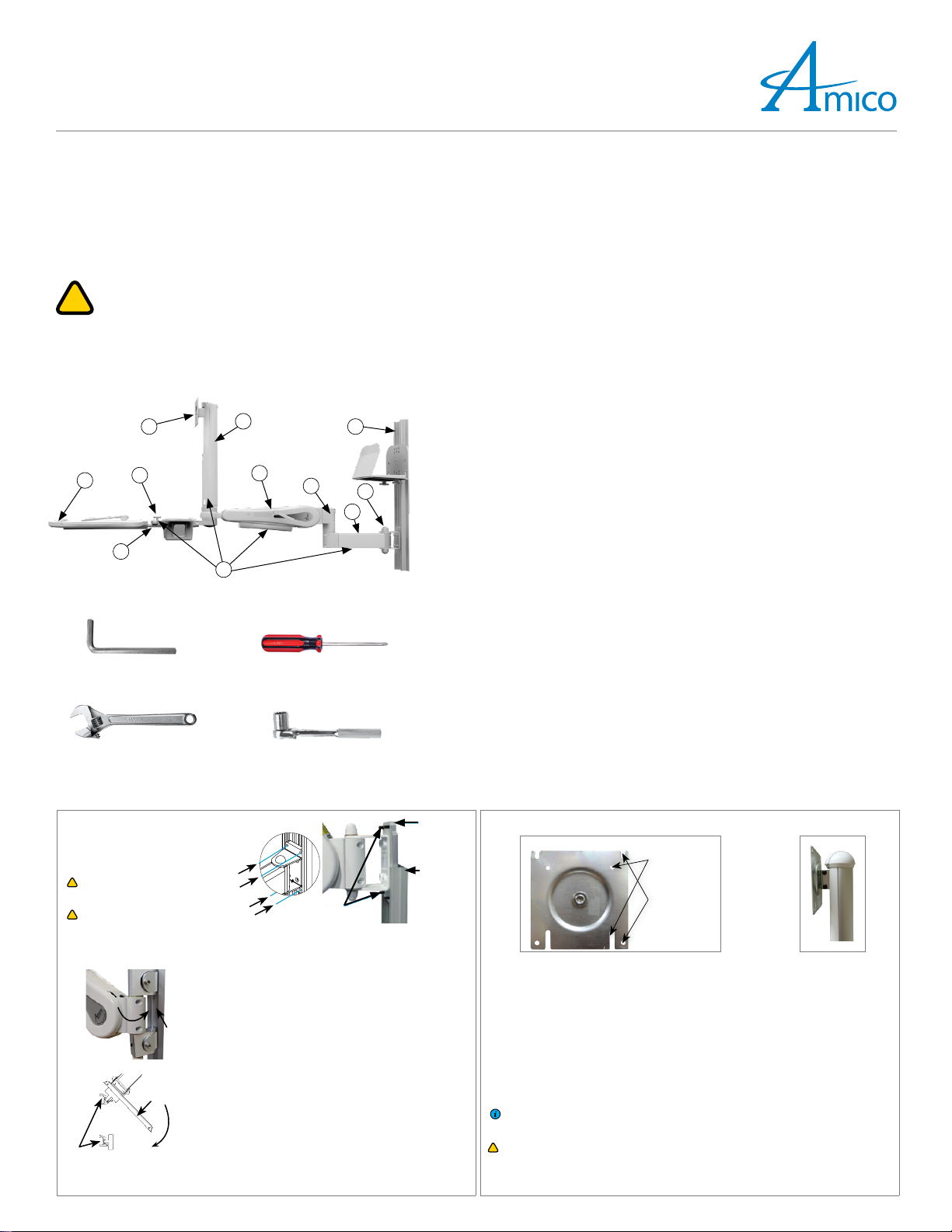
FIT
1. Swivel Post
For mounting and positioning of monitor.
2. Extension Arm
Extension arm to increase movement range of AHM ARM (if applicable).
3. Mounting Adapter
Different mounting adapters will be provided based on the rail system used.
4. Cable Management
Manage cables for the FIT station for a clutter-free environment.
5. Height-locking Lever
Locks arm at the desired height.
6. Counter-balance Bolt
Balance the weight of the monitor on the AHM ARM of the FIT.
7. Negative Tilt Knob
Tilts the keyboard tray’s back downwards for proper ergonomics in certain cases.
8. Keyboard Tray
Locationforkeyboard& mouse. (2x mousepads, 12x duallock coins provided; wrist restif purchased).
9. Rail System
For mounting the FIT station, varies depending on user’s selection. Rail is packed separately and must
be installed first.
10.VESA Head
For mounting the monitor.
11.Mouse/Scanner Holder
For storing mouse and hand-held scanners.
1
5
3
7
10
2
6
9
4
8
11
1. Installation to Structure 2. Installation to Monitor
Mounting on an MRS Rail
4x 1/4-20SET SCREWS. Use 1/8" (3 mm) Hex
Key to tighten.
!
WARNING: Never attempt to mount or
remove the AHMARM from the MRS RAIL
when a monitor is installed.
!
WARNING: Support AHM ARM until the SET
SCREWS are tightened, AHMARM can slide
down when SET SCREWS are not tightened.
VRS
RAIL
STANDARD
MONADAPTER
MRSRAIL
SETSCREWS
3 mm
ARSRAILS
MOUNTING
ADAPTER
CHANNEL
ARS
ADAPTERINSTALLED
Mounting on a VRS/Ohmeda Rail
Angle the AHM ARM from the left of the CHANNEL and guide the
ADAPTERS into the groove of the CHANNEL. Tighten SCREW with
a 3/16" Hex Key when V-ADAPTER is at the desired height. When
tightened, the SCREW will protrude from the other side. Fasten the
NUT to the SCREW to secure the V-ADAPTER. If the NUT cannot be
installed, the ADAPTER is not properly engaged. Check that all NUTS
and SCREWS are tightened to ensure the V-ADAPTER is locked.
Mounting on a Headwall
Pop out the cover from the MOUNTING ADAPTERCHANNEL to
access the SCREWS. Remove the 2x SCREWS and LOCK WASHERS to
free bottom MOUNTINGADAPTER. Install it into the bottom RAIL
by angling the upper lip into the inside lip of the ARSRAIL, pull the
lever back against the MOUNTINGADAPTER and push the ADAPTER
into the ARS RAIL. Once secure, release the lever.
Install the remaining MOUNTING ADAPTER into the top ARS RAIL
the same way as step 1, ensuring the 2xHOLES on the bottom
MOUNTING ADAPTER can be seen through the MOUNTINGADAPTER
CHANNEL. Secure the CHANNEL to the bottom MOUNTINGADAPTER
using the SCREWS and LOCKWASHERS you removed in step 1.
1. Determine the monitor mounting configuration. VESA75 (75 mm x 75 mm M4 thread) or VESA100
(100 mm x 100 mm M4 threads).
2. VESA 100 Configuration: 2x SCREWS are partially threaded into the top 2xHOLES in the back of the
monitor. The monitor can then be hung up on the VESAHEAD through the 2x slots at the top. Insert
2x more SCREWS through the VESA100MOUNTINGHOLESat bottom, tighten all SCREWS. (Figure 1)
3. VESA 75 Configuration: Rotate the VESAHEAD so the 2x slots for the VESA75 configuration are
located at the top. Partially thread 2x SCREWS into the top 2x HOLES in the back of the monitor.
The monitor can then be hung up on the VESAHEAD through the 2x slots at the top. Insert 2x more
SCREWS through the VESA 100 mounting holes at the bottom and tighten all SCREWS.
4. When removing the monitor, the monitor ARM and the monitor should be placed at the highest
position (Figure 2). Remove the 2x bottom SCREWS from the VESAPLATE, loosen the top 2x SCREWS,
and lift the monitor off the VESAPLATE.
NOTE: 4x M4SCREWS are provided for mounting the monitor to the VESAHEAD, different SCREWS
may be needed if the provided SCREWS are not the right size, standoffs may be needed
depending on the hole pattern on the monitor.
!
WARNING: Ensure that the AHM ARM is in the highest vertical position and locked before mounting
or removing devices from the FIT station.
FRONTOFTHE VESA75/100 M4MOUNTING
HOLEFORVESA75
M4MOUNTING
HOLEFOR
VESA100
Figure 1 Figure 2
Falcon IT (FIT)
Quick Installation and Adjustment Instructions
Amico Accessories Inc. | 85 Fulton Way, Richmond Hill, ON L4B 2N4, Canada | www.amico.com
Toll Free Tel: 1.877.264.2697 | Tel: 905.763.7778 | Fax: 905.763.8587 | Email: info@amico-accessories.com 2
3. Rotation (AHM Side-to-side) 4. HeadTilt and Rotation
SECOND ARM ROTATED
TO ROTATE AHM ARM:
ROTATE MID POINT
AHM ARM
EXTENSION ARM
BOLTAT EXTENSION ARM
EXTENSION ARM ROTATED
TO ROTATE AT FIRST ARM
ROTATE END POINT
BOLTATEXTENSION
!
WARNING: In AHMARM(s) with extensions, both armsw have a 180°rotation. Ensure proper clearance
around the arm(s) to avoid collision (if applicable).
Themonitorcan swivel 360° (clockwise/counter-clockwise,left/right), itcanalso tilt up/downby +/-15°.
Adjusting Tilt Tension: Tighten or loosen the LARGE SCREW on the MOUNTINGBRACKET and then
tighten or loosen the 2x SMALL SCREWS to fine tune the tension. (Figure 1)
Adjusting Swivel Tension: Slightly (one turn) loosen/tighten the COUNTER-BALANCEBOLT at the base
of the KEYBOARDTRAY, to adjust the rotational tension of both the monitor and the KEYBOARDTRAY,
slightly loosen/tighten the 3x PHILLIPSHEAD SCREWS at the base of the KEYBOARDTRAY. (Figure 2)
!
WARNING: Be sure to support the monitor if adjusting the tilt angle with the monitor mounted.
!
WARNING: After the monitor is installed, tighten large and small tilt adjustment SCREWS to the
tightest position possible with the weight of the monitor attached. Alternate between tightening
LARGE SCREWS and SMALL SCREWS until the appropriate tension is reached.
± 15°
SMALL
SCREWS
LARGE
SCREW
± 360°
Figure 1
KEYBOARDBASE
SCREWSFOR ADJUSTING
TENSION OF BOTH
KEYBOARD TRAY AND
SWIVELBLOCK
SCREWSFOR ADJUSTING
TENSIONOFSWIVEL
BLOCKONLY
Figure 2
5. FIT Post Cable Management 6. Height Locking Lever Adjustments
1. There are 2x FITCABLEGUIDE CHANNELS in the
SWIVELPOST, which is covered by the SWIVEL
POSTCABLE COVER.
2. Pop out the SWIVELPOSTCABLE COVER, take
your power cable for your all-in-one and place
the cable gently into the GUIDECHANNELS
towards your AHMARM (Figures 1 & 2).Take
your cables from the keyboard tray and place
the cables into the GUIDECHANNELS towards
your all-in-one.
!
WARNING: Do not bunch cables together in
one CABLEGUIDE CHANNEL. Use separate
CHANNELS for each cable.
CABLEGUIDE
CHANNEL CABLELAID SWIVEL POST
CABLECOVER
Figure 1 Figure 2 Figure 3 To adjust the AHMARM height, alwaysbesureto loosen the HEIGHT LOCKINGLEVERrst.
INSERT HEIGHTLOCKINGLEVER HEIGHTLOCKINGLEVER:
ROTATE COUNTER-CLOCKWISE
TO RELEASE, ROTATE CLOCKWISE TO LOCK.
7. Counter Balance
!
8. Cable Management
Loosening or tightening the COUNTER-BALANCE
BOLT will adjust the resistance of the arm. When properly counter-balanced, the arm should
remain in neutral position when unlocked.
OPENINGTOTHECOVER
HEIGHT LOCKING LEVER
COUNTER-BALANCE BOLT(1/2")
COUNTER-BALANCE BOLT(1/2”)
!
WARNING: Do not over rotate the COUNTER-BALANCEBOLT. Once you feel resistance, stop counter-balancing.
Forcing the COUNTER-BALANCE BOLT will damage the internals of the AHM ARM and void the warranty.
!
WARNING: KICK-BACK motion: when the AHMARM is locked and not in the highest position, it is capable of
rapidly lifting to the highest position once the HEIGHTLOCKINGLEVERis released.
R
A
P
I
D
L
I
F
T
I
N
G
(
K
I
C
K
-
B
A
C
K
)
Insert cables into CABLEGUIDE, then squeeze CABLEGUIDE and press onto the bottom of the AHMARM.
CABLE GUIDE
BOTTOM SIDE OFTHE AHMARM
CABLE COVER
CABLE GUIDE
CABLE GUIDE
BOTTOM SIDE OFTHE AHMARM
GROOVES
BOTTOM SIDE OF CABLECOVER
TOROTATE ATSECONDARM
AA-QG-WALL-MOUNTED-COMPUTER-WORKSTATION-FALCON 07.25.2012

Other manuals for Falcon IT

2

Other Amico Medical Equipment manuals

Amico ADULT 11 User manual

Amico

Amico ADULT 11 User manual

Amico Majestic Series User manual

Amico

Amico Majestic Series User manual

Amico Majestic Series User manual

Amico

Amico Majestic Series User manual

Amico ATA-8-32 User manual

Amico

Amico ATA-8-32 User manual

Amico AHM Guide

Amico

Amico AHM Guide

Amico Mira LED Exam Light Manual

Amico

Amico Mira LED Exam Light Manual

Amico Diagnostic Station User manual

Amico

Amico Diagnostic Station User manual

Amico ICE 25 Service manual

Amico

Amico ICE 25 Service manual

Amico S-H-300 Manual

Amico

Amico S-H-300 Manual

Amico LightMaster Multifunction Switch Manual

Amico

Amico LightMaster Multifunction Switch Manual

Amico Roll Stand INE-0909-12-12-F4-M User manual

Amico

Amico Roll Stand INE-0909-12-12-F4-M User manual

Amico GoLift User manual

Amico

Amico GoLift User manual

Amico Reflection Series User manual

Amico

Amico Reflection Series User manual

Amico HMA-WT-LEDMNT Technical specifications

Amico

Amico HMA-WT-LEDMNT Technical specifications

Amico Exergen 134201 Product manual

Amico

Amico Exergen 134201 Product manual

Amico ICU Series Manual

Amico

Amico ICU Series Manual

Amico Gamma LED Series Manual

Amico

Amico Gamma LED Series Manual

Amico CS-SLVP-ADA-00 Product manual

Amico

Amico CS-SLVP-ADA-00 Product manual

Amico ARM Instructions for use

Amico

Amico ARM Instructions for use

Amico S-M-100 Manual

Amico

Amico S-M-100 Manual

Amico Apollo MS-SC Manual

Amico

Amico Apollo MS-SC Manual

Amico S-AM1-300X Manual

Amico

Amico S-AM1-300X Manual

Amico AC-200C Installation and operation manual

Amico

Amico AC-200C Installation and operation manual

Amico Mira LED Exam Light Manual

Amico

Amico Mira LED Exam Light Manual

Popular Medical Equipment manuals by other brands

Alu Rehab Netti 4U comfort CED user manual

Alu Rehab

Alu Rehab Netti 4U comfort CED user manual

Pulmodyne Control-Cric quick start guide

Pulmodyne

Pulmodyne Control-Cric quick start guide

Gate Bure Rise & Go DB 56-309 Technical manual

Gate

Gate Bure Rise & Go DB 56-309 Technical manual

College Park Victor Technical instructions

College Park

College Park Victor Technical instructions

Breg NINJA Instructions for use

Breg

Breg NINJA Instructions for use

Ferno Kit 069-5796 manual

Ferno

Ferno Kit 069-5796 manual

Chattanooga Intelect Advanced Therapy System manual

Chattanooga

Chattanooga Intelect Advanced Therapy System manual

Ambu Mini Perfit ACE Instructions for use

Ambu

Ambu Mini Perfit ACE Instructions for use

iCoolsport iCool MiPod Series owner's manual

iCoolsport

iCoolsport iCool MiPod Series owner's manual

Inspired by drive Ultima Access BCUA-8626M instructions

Inspired by drive

Inspired by drive Ultima Access BCUA-8626M instructions

Otto Bock 50R20 Dorso Osteo Care Instructions for use

Otto Bock

Otto Bock 50R20 Dorso Osteo Care Instructions for use

ResMed Ultra Mirage II user guide

ResMed

ResMed Ultra Mirage II user guide

Huntleigh Smartsigns Compact SC1000 Instructions for use

Huntleigh

Huntleigh Smartsigns Compact SC1000 Instructions for use

Enraf Nonius ManuXelect manual

Enraf Nonius

Enraf Nonius ManuXelect manual

Guardian Guardian IC-5107 parts list

Guardian

Guardian Guardian IC-5107 parts list

Stryker 1188HD troubleshooting guide

Stryker

Stryker 1188HD troubleshooting guide

Brainlab CRANIAL/ENT OPTICAL TRACKING Instrument User Guide

Brainlab

Brainlab CRANIAL/ENT OPTICAL TRACKING Instrument User Guide

Air Techniques Rxonly ProVecta 3D Prime operating instructions

Air Techniques

Air Techniques Rxonly ProVecta 3D Prime operating instructions

manuals.online logo
manuals.online logoBrands
  • About & Mission
  • Contact us
  • Privacy Policy
  • Terms and Conditions

Copyright 2025 Manuals.Online. All Rights Reserved.