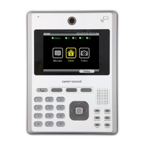
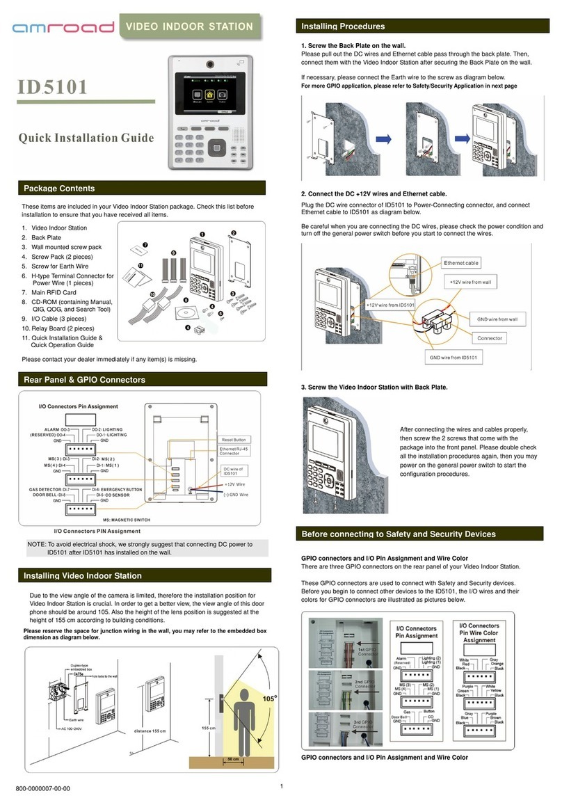
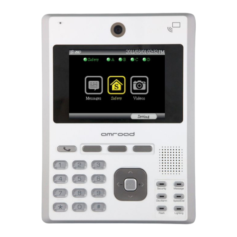
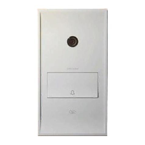
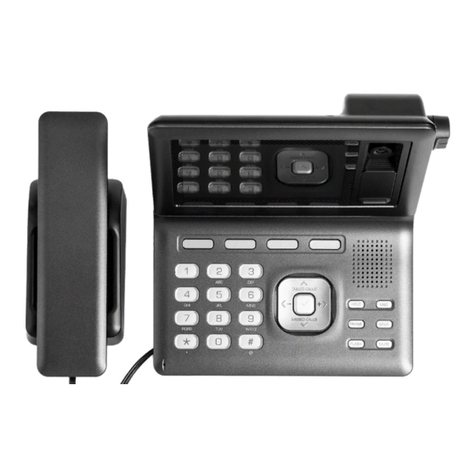
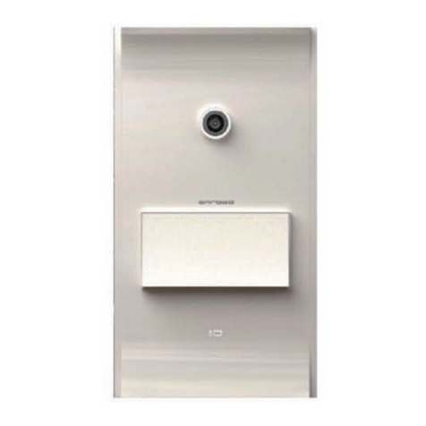
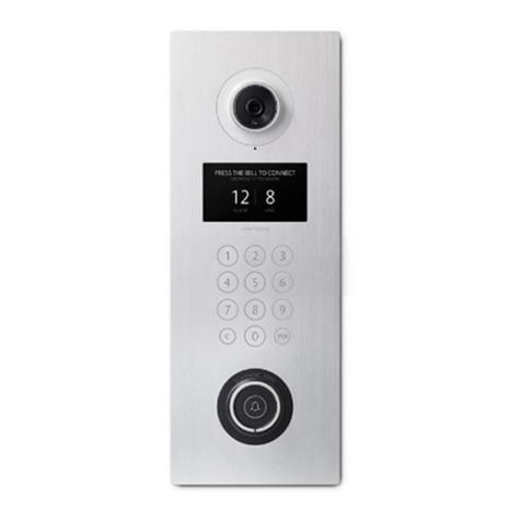
Amroad DP100-25 User manual


COPYRIGHT
Copyright
© 2012 Amroad Technology Inc.
All Rights Reserved. No part of this publication may be reproduced, transmitted, transcribed, stored in a retrieval system or translated into any
language in any form or by any means without the express written permission of Amroad Technology Inc. To obtain consent, write to the
attention of Amroad Technology Inc.
Document No. DP100-25 2012-0716
www.amroad.com.tw
DISCLAIMER
Amroad reserves the right to change product specification without prior notice.
Changes may be made to the information in this publication without obligation to notify. Amroad shall not be liable for technical or editorial
errors contained herein.
TRADE MARKS
Amroad logo is copyright of Amroad Technology Inc. All other products, services or trade marks mentioned in this document are the property of
their respective owners, companies or organizations.

CONTENTS
i
Contents
COPYRIGHT................................................................................................................................................................................................... II
CONTENTS ............................................................................................................................................................................................... I
CHAPTER 1 : INTRODUCTION............................................................................................................................................................... 1
WELCOME..................................................................................................................................................................................................... 1
GENERAL APPLICATION OF DOOR ENTRY SYSTEM .......................................................................................................................................... 2
USE OF SIP................................................................................................................................................................................................... 4
CHAPTER 2 : KNOWING VIDEO DOOR PHONE ................................................................................................................................... 5
PACKAGE CONTENTS..................................................................................................................................................................................... 5
FRONT PANEL................................................................................................................................................................................................ 7
LED Light......................................................................................................................................................................................................... 8
REAR PANEL ................................................................................................................................................................................................. 9
Reset Button.................................................................................................................................................................................................. 10
VOID Sticker.................................................................................................................................................................................................. 10
DIMENSIONS................................................................................................................................................................................................ 10
DIMENSIONS................................................................................................................................................................................................ 11
CHAPTER 3 : INSTALLING VIDEO DOOR PHONE.............................................................................................................................. 12
SUGGESTED INSTALLATION POSITIONS ......................................................................................................................................................... 12
LIGHTING CONDITIONS................................................................................................................................................................................. 12
INSTALLING PROCEDURES............................................................................................................................................................................ 13
1. Insert the Wall Mounting Box into the Wall....................................................................................................................................... 13

CONTENTS
ii
2. Connect the DC wires and Ethernet Cable. ...................................................................................................................................... 14
3. Install Video Door Phone into the Mounting Box............................................................................................................................. 15
CHAPTER 4 : CONFIGURING VIDEO DOOR PHONE.......................................................................................................................... 19
FINDING VIDEO DOOR PHONE ON NETWORKS .............................................................................................................................................. 19
SYSTEM - BASIC SETTINGS .......................................................................................................................................................................... 21
System – Network Settings ........................................................................................................................................................................... 23
System Login Name ...................................................................................................................................................................................... 24
System Reboot.............................................................................................................................................................................................. 24
Phone Settings – Video ................................................................................................................................................................................. 25
Phone Settings – Audio ................................................................................................................................................................................. 27
SIP SERVICES ............................................................................................................................................................................................. 29
ENTRANCE SETTINGS – EXTENSIONS ........................................................................................................................................................... 31
ENTRANCE SETTINGS – GPIO ..................................................................................................................................................................... 34
ENTRANCE SETTINGS –RFID....................................................................................................................................................................... 35
UPGRADE – FIRMWARE UPDATE................................................................................................................................................................... 37
CONFIGURATIONS........................................................................................................................................................................................ 39
AR APS...................................................................................................................................................................................................... 40
CHAPTER 5 : USING VIDEO DOOR PHONE........................................................................................................................................ 41
Making Calls From Video Door Phone .......................................................................................................................................................... 41
ANSWERING CALLS ON IP VIDEO PHONE ...................................................................................................................................................... 42
DP100-25 RFID CARD USAGE .................................................................................................................................................................... 43
Issue Master RFID Card First Time............................................................................................................................................................... 43
Issue a New Card with Master RFID Card..................................................................................................................................................... 43
OPEN THE DOOR ......................................................................................................................................................................................... 44
APPENDIX A : ELECTRONIC LOCK..................................................................................................................................................... 45
CONTENTS
iii
Electronic Lock .............................................................................................................................................................................................. 45
Electronic Bolt ............................................................................................................................................................................................... 45
Wiring Connection and Web Page Setup ...................................................................................................................................................... 46
Electronic Strike ............................................................................................................................................................................................ 47
Wiring Connection and Web Page Setup ...................................................................................................................................................... 47
APPENDIX B : REGULATORY INFORMATION..................................................................................................................................... 49
CE DECLARATION OF CONFORMITY (EUROPE) .................................................................................................................................. 50


DP100-25 VIDEO DOOR PHONE
1
A
mroad Technolo
gy
Inc.
Figure 1: DP100-25
Chapter 1 : Introduction
Welcome
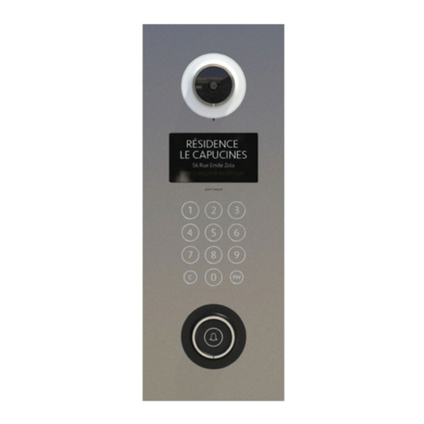
Thank you for choosing this Video Door Phone. This DP100-25 is designed to co-work with IP Video Phone to compose a SIP
based door entry system. Besides taking advantages of IP technologies, this system also can fully utilize the SIP protocol to link to
your SIP VoIP services. In other words, this system performs not only as an Intercom system, but also work with your SIP-based
community system.
This product provides many extraordinary features:
z Talk to visitors with real time video and voice on IP Video Phone or Video Indoor Station.
z Open electronic door by indoor IP Video Phone or RFID card reader.
z Support SIP (Session Initiation Protocol) VoIP services, it is able to forward visitor calls to your
mobile phone or office phone.
z Support H.263 formats.
z Support G.711 audio formats.
z Build-in electronic door opener interface.
z Build-in speaker and microphone.
z Friendly web user interface for configuration and management.
Please read this user guide carefully before taking any installation action. Please contact your dealers or
system integrators if you have questions.

DP100-25 SI MANUAL
2
A
mroad Technolo
gy
Inc.
Figure 2: Single Unit Application
General Application of Door Entry System
There are two major models of Video Door Phone: one is single unit model, the other is community model. They are applied on
different conditions. Please see following descriptions:
Villa Application
DP100-25 is designed for building,
apartment or community. It is also used
for single house or villa. Please see
Figure 2.
Using a home IP PBX to connect all
SIP-based devices.
Communicate with each device simply
with extension numbers.
Connect to SIP VoIP services via
Internet.
Community Application
DP100-25 is designed for building,
apartment or community.
Please see Figure 3
Connect each house or apartment

DP100-25 VIDEO DOOR PHONE
3
A
mroad Technolo
gy
Inc.
with a large IP PBX.
Residents can check
visitors, monitor public
areas or call each others
with extension numbers.
Connect to SIP VoIP
services via Internet.
Figure 3: Community Application

DP100-25 SI MANUAL
4
A
mroad Technolo
gy
Inc.
Use of SIP
SIP, initial of Session-Initiation-Protocol, it is an application-layer control (signaling) protocol for creating, modifying, and terminating
sessions with one or more participants. These sessions include Internet telephone calls, multimedia distribution, and multimedia
conferences. Simply say, SIP is a most commonly used protocol that used to interconnect SIP Enabled PBX and/or SIP User
Agents to each other to establish voice and
video sessions between each other over an IP
Network.
There are few typical applications of SIP
products, please refer to Figure 4
Make a video phone call from indoor IP
Video Phone to outside IP Video Phone.
Make a video phone call from softphone on
notebook to IP Video Phone.
View SIP Camera video from IP Video
Phone at office.
View SIP Camera video from you mobile
phone.
Figure 4: General SIP Application

DP100-25 VIDEO DOOR PHONE
5
A
mroad Technolo
gy
Inc.
Chapter 2 : Knowing Video Door Phone
Package Contents
The following items are included in your Video
Door Phone package. Check this list before
installation to ensure that you have received all
items.
n Video Door Phone Unit
o Wall Mounting Box
p Terminal Connectors
q Screw Pack (4 pieces of M6 x 20mm)
\ Wrench
] Screw for Earth Wire
^ Wall mounted screw pack
_ H-type Terminal Connector for Power Wire
` Cord End Terminal (12 pieces)
a Plastic Protective Cover
Master RFID Card
Quick Installation Guide & Quick Start Guide
(Englis h/Chinese version)
Please contact your dealer immediately in case
that any item(s) is missing. Figure 5: Package Contents

DP100-25 SI MANUAL
6
A
mroad Technolo
gy
Inc.

DP100-25 VIDEO DOOR PHONE
7
A
mroad Technolo
gy
Inc.
Front Panel
Figure 6: Front Panel

DP100-25 SI MANUAL
8
A
mroad Technolo
gy
Inc.
LED Light
There are IR LEDs on both sides of CMOS lens for light compensation. Blue LEDs are behind the keypads, and LCD screen
is with blue backlight. The LED and blue backlight will light when any button/keypad is pressed. And, the LED and backlight
can be set through WEB UI.
LEDWEBUISETTINGDESCRIPTION
SleepModeDisableTheblueLEDwilllightOnwhenanykeypadispressed.And,thekeypadLED
willbeturnedoffin5~10secondsafterphonecallisended.
KeypadLED
SleepModeEnableBeyondthetimeperiodofSleepMode,KeypadLEDwillalwaysbeON.
Backlight
OpenOnThebacklightwillalwayslightON.
LCDBacklight
Backlight
OpenOffTheLEDbacklightwilllightOnwhenanykeypadispressed.And,theLED
backlightwillbeturnedoffafteroneminuteafterphonecallisended.

DP100-25 VIDEO DOOR PHONE
9
A
mroad Technolo
gy
Inc.
Rear Panel
Figure 7: Rear Panel and Connectors

DP100-25 SI MANUAL
10
A
mroad Technolo
gy
Inc.
Reset Button
The default IP type setting of Video Door Phone is “DHCP Client “.
1. Pressing the reset button for 3 seconds=>DP100-25 will turn into Statics IP mode as "192.168.0.50" and reboot by itself.
2. Pressing for over 6 seconds and Green LED ON=>Turn to DHCP mode as the default value and reboot by itself (Restore
to factory setting).
VOID Sticker
There is a “VOID” sticker on the rear side of the DP100-25.
This VOID sticker is used to prevent opening the case and tampering concealment.
WARNING: “VOID” means “WARRANTY VOID IF SEAL BROKEN”
Amroad shall not be responsible under warranty if the VOID sticker is
broken or removed.
Figure 8: VOID Sticker

DP100-25 VIDEO DOOR PHONE
11
A
mroad Technolo
gy
Inc.
Dimensions
Figure 9: Dimensions

DP100-25 SI MANUAL
12
A
mroad Technolo
gy
Inc.
Chapter 3 : Installing Video Door Phone
Suggested Installation Positions
Due to the view angle of the camera lens is limited, to install the Video Door
Phone in a correct position to get better view is very important. Suggested height
of the lens position is at the height of 155 cm according to building conditions.
And, the distance from the bottom of wall box to the ground is 123.5 cm. View
angle of this door phone is 105
O. Please see an example of installation position on
Figure 10.
Lighting Conditions
The Lens of this device is able to see IR (Infra-Red) light, therefore you may also
implement with an IR light. Please note, IR light only delivers black & white
images, and the objects looks odd in some conditions. Please see the spotlight
example on Figure 10.
Figure 10: Installation Position

DP100-25 VIDEO DOOR PHONE
13
A
mroad Technolo
gy
Inc.
Installing Procedures
1. Insert the Wall Mounting Box into the Wall.
Cutting a hole that is able to contain the Wall Mounting Box and prepare the DC +12V and Ethernet cable ready. Then insert
the box into the wall and pull the DC wires and Ethernet cable through the hole on the box. You must place the Box very
precisely in horizontal in order to keep the Video Door Phone in correct position.
Figure 11: Installing the Wall Mounting Box

DP100-25 SI MANUAL
14
A
mroad Technolo
gy
Inc.
2. Connect the DC wires and Ethernet Cable.
Connect the DC wire of DP100-25 to H-type power connector, and connect Ethernet cable to DP100-25 according to below
Figure 12. Please be careful when you are connecting the DC +12V, be sure to check the DC condition before you start to
connect the wires. Please screw the earth cable to the “Wall Mounting Box “.
Figure 12: Connecting Cable & Wires
Table of contents
Other Amroad Intercom System manuals

Amroad
Amroad AMROAD P3 User manual

Amroad
Amroad XL COMMUNITY STATION User manual

Amroad
Amroad DP3211 User manual

Amroad
Amroad AMROAD P3 User manual

Amroad
Amroad DP3210 User manual

Amroad
Amroad DP101 Quick setup guide

Amroad
Amroad DB3100R User manual

Amroad
Amroad VP115 User manual

Amroad
Amroad DP101R User manual

Amroad
Amroad DP3210 User manual

Amroad
Amroad DP101 User manual

Amroad
Amroad DP3010R User guide

Amroad
Amroad ID5101 User manual

Amroad
Amroad DP3211 User manual

Amroad
Amroad ID5101-RN User manual

Amroad
Amroad DP3210 User manual

Amroad
Amroad DP101 User manual

Amroad
Amroad ID5101 User manual

Amroad
Amroad AMROAD P3 User manual

Amroad
Amroad DP3010R User manual